EN

When to Use Coaxial Cable Couplers in RF Installations
A coaxial cable coupler is a small part, but it deserves a system-level decision. In an RF installation, it joins two compatible coaxial runs or connects an existing cable to a serviceable section. That makes it useful during extension, repair, equipment relocation, and planned maintenance. It does not, however, erase the electrical and mechanical consequences of adding another interface to the signal path.
As a field installer, I start with the purpose of the join rather than the catalog listing. A coaxial cable coupler can be the cleanest answer when a tested cable run must be extended, when a damaged end needs a localized repair, or when a panel, surge device, or removable assembly requires a deliberate break point. If the installation is new and a single continuous cable can be routed correctly, fewer interfaces are usually simpler to inspect and manage.
What a coaxial cable coupler does—and what it does not do
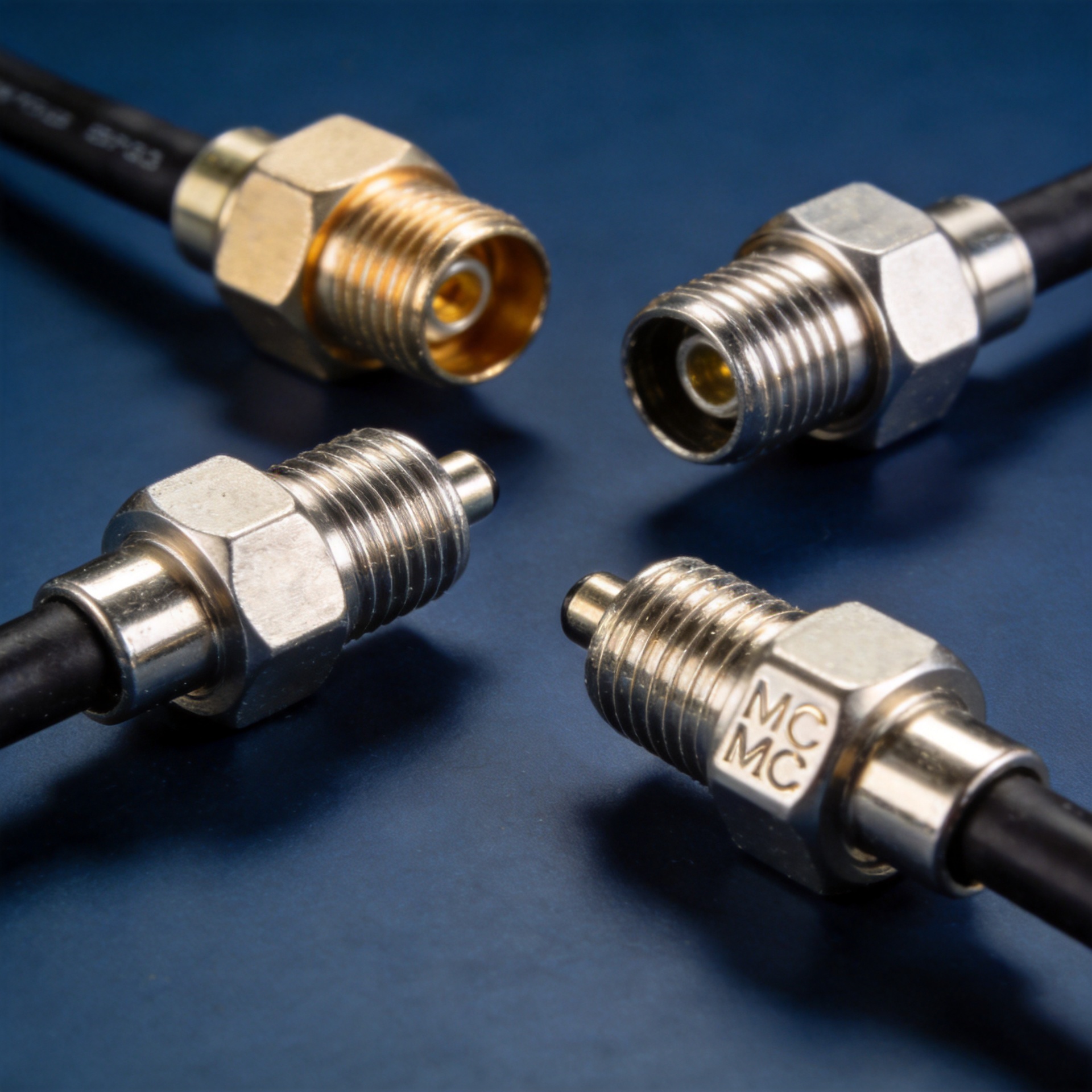
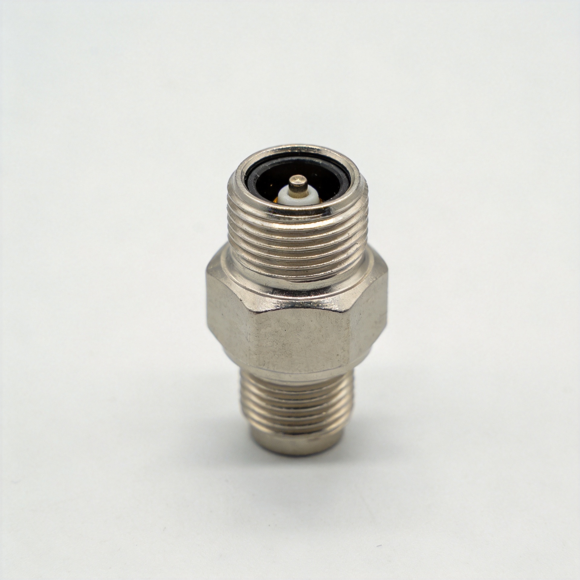
A coaxial cable coupler is generally an in-line female-to-female interface, although its exact connector family can vary. It lets two properly terminated cable ends mate without splicing the inner conductor and shield. For a short extension, a cabinet pass-through, or a replaceable feeder section, that serviceability can be valuable.
But a coax coupler is not a universal adapter. It cannot make unlike impedances, connector series, or cable constructions electrically equivalent. Nor should it be used as a shortcut for a cable that is too short because the routing plan was not checked. Every added mating interface is another point to verify for fit, cleanliness, torque, weather sealing, and RF performance.
Use a coaxial cable coupler for planned extensions and modular sections
The most straightforward use of a coaxial cable coupler is extending a run when both cable sections belong to the same RF system. This is common when an antenna feed must reach a relocated radio, when a rack is expanded, or when an existing route can be reused but needs a modest additional length. Start by confirming that the coupler and both cable assemblies have the same nominal impedance and compatible mating interfaces.
Modular sections are another good reason to use a coaxial cable coupler. A removable rooftop jumper, a test segment near a radio, or a cable section routed through a cabinet can be easier to replace than a single long assembly. In these cases, the interface is intentional: it creates an accessible maintenance point rather than an accidental weak link.
Use one for repair only when the repaired section can be qualified
A damaged cable end does not necessarily require replacing the whole route. If the damage is localized and the remaining cable is suitable, a coaxial cable coupler can join a newly terminated replacement section to the existing run. This approach is practical where pulling a new cable would interrupt other work or require access to difficult conduit.
There is an important condition: treat the repair as a new RF interface, not merely a mechanical fix. Inspect the dielectric and braid for hidden damage near the cut, use the termination method specified for the cable, and test the completed path. A cable that looks intact can still have an installation kink or dielectric deformation that visual inspection will not show. Where the loss budget or return-loss requirement is tight, replacing the full cable may be the lower-risk choice.
When a coupler is the wrong solution
Do not use a coax coupler to bridge a 50-ohm RF chain to a 75-ohm video or television chain simply because the connectors can be made to mate. Common RF systems use 50 ohms, while 75-ohm cable is used in other applications; the coupler should preserve the impedance of the system it serves. A mismatch can introduce reflections, so the correct decision is to verify the system design and select compatible cable, connectors, and coupler together.
A coaxial cable coupler is also a poor substitute for correcting excessive run length, poor cable routing, or a connector family mismatch. If the new equipment uses a different interface, choose a purpose-designed adapter or a cable assembly with the correct terminations. If the route is exposed to water, salt, UV, vibration, or frequent handling, determine whether the added interface can be protected and supported for that environment before installing it.
Check the electrical and mechanical fit before installation
Use this short review before specifying a coaxial cable coupler:
- Impedance: Keep the coupler consistent with the nominal impedance of the complete signal path.
- Connector interface: Confirm the gender, series, thread or coupling mechanism, and mating dimensions at both ends.
- Frequency and power: Verify that the component is appropriate for the operating band and power conditions of the installation.
- Loss and return loss: Include the added interface in the RF link budget, especially in short or reflection-sensitive paths.
- Environment: Plan strain relief, sealing, corrosion protection, and physical support for outdoor or high-vibration locations.
- Access: Put a serviceable interface where technicians can inspect and re-mate it without bending or stressing the cable.
The specification that matters most depends on the site. In a controlled indoor test setup, an accessible coax coupler may be a sensible way to reconfigure equipment. On an exposed antenna run, long-term sealing and strain relief may matter just as much as the nominal electrical rating.
Installation practices that protect RF performance
Clean the mating surfaces, align the interface correctly, and use the torque method specified for that connector family. Over-tightening can damage insulating material, center contacts, or mating surfaces; under-tightening can leave an unstable interface. Neither condition is a good trade for a link that must remain stable after commissioning.
Then support the cable on both sides of the coaxial cable coupler. The coupler should not carry the weight of a hanging cable or absorb repeated bending. For outdoor locations, use an appropriate weatherproofing method and inspect the seal as part of scheduled maintenance. After installation, test the completed path with the measurement method appropriate to the system, such as a continuity check, insertion-loss measurement, or sweep/return-loss test.
Choosing a supplier for compatible RF cable assemblies
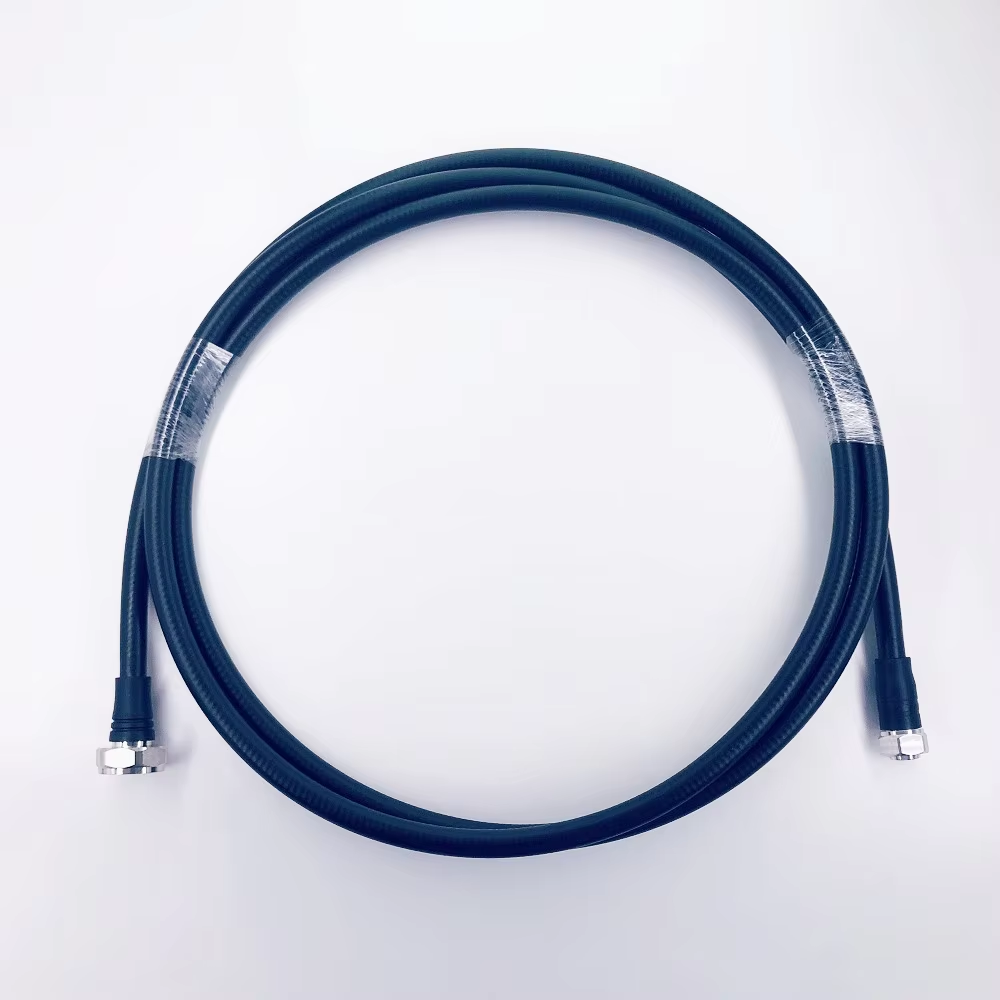
For projects that need a matched cable-and-connector solution, work from the complete interface requirement: cable type, connector family, impedance, environment, and desired assembly length. Zhenjiang Jiewei supplies RF connectors, feeder cables, cable assemblies, and loads for telecom and broadcast applications. Where an N-type cable termination is part of the design, review the actual cable and connector compatibility rather than assuming two similarly named parts will fit. For example, the RF N Female Connector for RG58, 3D-FB, LMR195 and LMR200 Cable should be evaluated against the specified cable construction and installation requirements.
Make the coupler a deliberate interface
The right time to use a coaxial cable coupler is when it creates a controlled, compatible, and testable connection: a planned extension, a modular service section, a qualified repair, or an accessible equipment interface. Avoid using it as a quick fix for incompatible components or an unexamined routing problem. When impedance, connector fit, environment, and post-installation testing are all addressed, a coax coupler can add useful flexibility without turning the RF path into an unknown.