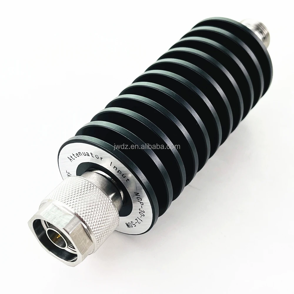
The power handling capacity basically means how much RF input (either continuous or pulsed) an attenuator can take before it starts to break down. Most compact surface mount versions work well with inputs between 2 watts and 50 watts. But when we get into those bigger coaxial models designed for serious applications, they can actually handle up to 1000 watts if the thermal management is done right. Something worth noting about pulse rated attenuators too – these bad boys can often stand peak power levels that are anywhere from 10 to even 100 times higher than what they're rated for continuously, though this all depends heavily on the duty cycle. Manufacturers usually list these specifics in their component documentation so engineers know what to expect under different operating conditions.
Exceeding rated input power leads to excessive heat, risking signal distortion or component failure. Systems operating at 50W should use attenuators with a 25%–50% power margin to accommodate transient spikes and ensure long-term reliability.
Designers must consider both average and peak power demands. For example, a 5G base station generating 200W peak signals requires an attenuator rated for at least 250W to maintain performance and prevent premature wear.
In 1000W attenuators, passive heat sinks reduce thermal resistance by 30–50%, while forced-air cooling significantly extends lifespan in continuous-duty applications by maintaining stable internal temperatures.
A laboratory using a 100W-rated attenuator for 150W signals observed a 40% failure rate within 500 hours, underscoring the importance of adequate power margins in millimeter-wave testing environments.
Accurate attenuation selection is essential for reliable signal regulation in RF systems. A 0.5 dB error can result in ±12% power measurement inaccuracies in millimeter-wave applications, making precision vital for 5G and aerospace testing.
Attenuators operate logarithmically—each 3 dB reduction halves the signal power. Engineers can calculate target output using:
High-precision attenuators maintain ±0.1 dB tolerance to avoid compounding errors in multi-stage systems. Studies show that designs with less than 1 dB attenuation uncertainty achieve 92% higher test repeatability than those with ±2 dB tolerance.
| Attenuation Range | Typical Applications | Accuracy Requirement |
|---|---|---|
| 0-10 dB | Power amplifier tuning | ±0.25 dB |
| 10-30 dB | Receiver protection | ±0.5 dB |
| 30-60 dB | EMI/EMC testing | ±1.0 dB |
Higher attenuation levels increase power dissipation—every 10 dB rise in fixed attenuators results in a 10° increase in heat generation, necessitating improved thermal management.
Today's advanced systems feature real time adaptive attenuation controllers capable of adjusting decibel levels automatically. These controllers work with three main factors: correcting for temperature changes at around -0.02 dB per degree Celsius, accounting for signal loss across different frequencies from 0.1 to 40 GHz range, and scaling predictions for those sudden bursts we see in things like 5G NR frames. Looking at actual field performance, manufacturers report that these intelligent systems cut down on calibration requirements by roughly two thirds when used in automated testing setups. What's really impressive is they keep within a tight margin of error too, staying stable within plus or minus 0.15 dB even after thousands of adjustments. This kind of reliability makes a big difference in production environments where consistent results matter most.
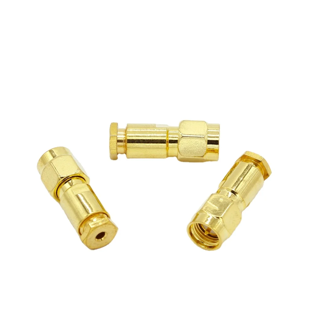
RF attenuators are critical for balancing signal strength across 5G, aerospace, and test systems, with four main types offering distinct trade-offs.
Fixed attenuators deliver consistent attenuation (e.g., 3 dB, 10 dB, 20 dB) using passive designs, ideal for stable environments. A 2023 study found they achieve ±0.2 dB accuracy under controlled conditions but lack flexibility for dynamic signal conditions.
Step attenuators allow discrete adjustments (e.g., 1 dB increments) via manual switches, while variable models offer continuous analog tuning. These are effective in field testing where input power fluctuates up to 30%, helping prevent signal overload.
Digitally controlled attenuators integrate with automation software, enabling millisecond-level adjustments essential for 5G beamforming and radar calibration. However, switching latency (typically 5–20 ms) must align with real-time system requirements.
Manual attenuators reduce initial costs by 40–60% but require physical access, limiting their use in remote or automated setups like phased array testing. Lifecycle analyses show digital models achieve 98% reliability over 50,000 cycles, justifying their higher cost in mission-critical applications.
Impedance matching maximizes power transfer and minimizes reflections that degrade signal integrity. Research from Cadence (2023) indicates mismatches can cause up to 20% signal loss and introduce phase errors, especially in high-frequency systems like 5G and satellite communications. Poor matching worsens VSWR, affecting measurement accuracy in precision environments.
When evaluating how well attenuators perform during precision tests, there are three main factors worth looking at: voltage standing wave ratio (VSWR), the range of frequencies they work with, and their tolerance levels for signal loss. For high frequency stuff like 5G networks and mmWave tech, keeping the VSWR below 1.5 to 1 is really important because it cuts down on those annoying signal reflections. Most modern day attenuators can handle signals all the way up to 40 GHz, which makes them suitable for pretty much any RF application out there these days. The top quality ones actually maintain a tight ±0.2 dB tolerance, something that makes measurements much more repeatable when running tests. According to research published by Telcordia in 2023, almost two thirds of problems encountered in labs come down to picking the wrong frequency range for the equipment being used.
Annual calibration using NIST-traceable standards ensures attenuators remain within ±0.1 dB of factory specifications. Automated calibration systems now achieve 99.8% reproducibility in ATE environments, reducing human error by 43% (EMC Journal, 2024). Traceability documentation is required for ISO/IEC 17025 compliance in defense and medical device testing.
Industry data shows that 95% of RF measurement errors in labs result from attenuators operating beyond their power limits or outside calibrated frequency ranges. A 2024 validation study found replacing legacy 6 GHz attenuators with 40 GHz-rated units reduced signal distortion by 38% in automotive radar testing.
In mmWave phased array calibration, engineers report that 0.05 dB attenuation consistency improves beamforming accuracy by 27% compared to standard ±0.5 dB components.
Power handling capacity refers to the amount of RF input—continuous or pulsed—that an attenuator can withstand before failing.
Proper thermal management is crucial for high-power attenuators to prevent overheating, ensure reliability, and extend component lifespan.
Impedance matching is vital to maximize power transfer, reduce signal reflections, and maintain signal integrity, especially in high-frequency systems.
Attenuation value influences signal power logarithmically, impacting the accuracy of power output calculations and measurement repeatability.
Smart attenuation algorithms offer real-time adaptive power adjustments, improving efficiency and precision in complex RF systems like 5G networks.

Copyright © 2024 by Zhenjiang Jiewei Electronic Technology Co.,Ltd - Privacy Policy
 Hot News