Base stations require cables that maintain signal integrity across frequencies up to 6 GHz while resisting environmental stressors like temperature shifts and moisture. These systems demand <20 dB return loss and stable 50-ohm impedance to prevent signal reflections, which is essential for reliable voice and data transmission in cellular networks.
The layered design of RF coaxial cables combines precision conductors with advanced dielectric materials to balance flexibility and shielding efficiency. Unlike rigid waveguides, coaxial variants adapt to tight bends in tower installations while delivering <0.3 dB/m attenuation at 3.5 GHz meeting critical performance benchmarks for 5G NR deployments.
Operators reported 38% fewer site visits when using double-shielded RF coaxial cables in mmWave small cells during 2023 field trials. This improved reliability stems from innovations such as foam-injected dielectrics, which help minimize latency spikes under peak traffic loads.
| Criterion | Coaxial | Waveguide | Fiber |
|---|---|---|---|
| Installation Cost | $12/m | $45/m | $28/m |
| Frequency Range | DC 110 GHz | 1 100 GHz | N/A (light-based) |
| Weather Resistance | High | Moderate | Low |
| Coaxial cables dominate last-mile connections due to their cost-to-performance ratio in RF environments, especially where metallic conduits already exist. While fiber excels in backhaul applications, its susceptibility to connector oxidation makes coaxial the preferred solution for antenna-facing links. |
RF coaxial cables suffer from signal loss mainly because of three things. First there's dielectric absorption where about 0.8 to 1.5 percent of energy gets lost in those standard foam PE materials. Then we have conductor resistance which can actually take away up to 25% of the signal strength in braided copper cables. And finally, poor shielding leads to radiation losses too. A recent report from the Telecommunications Standards Institute found something interesting though. Their 2023 research showed that modern high frequency base stations operating between 3.5 and 28 GHz degrade signals roughly 23% quicker compared to older sub-6 GHz systems when all these factors combine. This matters a lot for network operators trying to maintain quality connections across different frequencies.
Standard RF coaxial cables tend to lose signal strength at a rate of around 18% for every GHz increase in frequency. Most common models will drop more than 3 dB after just 100 feet when operating at 6 GHz frequencies. Things look much better at the lower end though signals below 1 GHz typically experience less than half a decibel loss over the same distance. To combat these losses, engineers design cables with stable impedance characteristics. High quality cables can maintain their 50 ohm rating within plus or minus 1 ohm all the way from DC up to 40 GHz, which makes them reliable across a wide range of applications where signal integrity is critical.
For every additional 50 feet of cable, signal strength drops by about 0.75 to 1.2 dB in those 4G and 5G networks. That's actually pretty significant when we remember the FCC wants less than 2 dB loss for those final connections right at the customer end. Most folks in the field suggest keeping cables shorter than 150 feet when working with sub-6 GHz frequencies. They also tend to use some fancy impedance matching tricks which apparently cut down on those annoying reflection losses by around two thirds. The Wireless Infrastructure Association mentioned this in their 2022 report, so it's definitely something professionals are paying attention to these days.
One big city telecom company managed to slash macrocell signal loss down from around 4.2 dB all the way to just 1.8 dB after swapping out standard RG-8 cables for these new nitrogen-filled foamed dielectric versions. The results were pretty impressive too. Download speeds shot up about 41% in those crowded downtown zones where everyone's fighting for bandwidth. And on top of that, each base station used 18 fewer watts at every cell site location. That might not sound like much until you realize it adds up to roughly $2,100 saved on electricity bills each year for every single tower they operate.
Seventy-eight percent of mobile operators now prioritize ultra-low-loss cables (<0.5 dB/100 ft at 28 GHz) for mmWave deployments, driven by 5G NR channel bandwidth requirements. The 2024 Mobile Networks Report highlights a 290% year-over-year rise in silver-plated conductor adoption, which enhances high-frequency conductivity by 27% compared to standard copper designs.
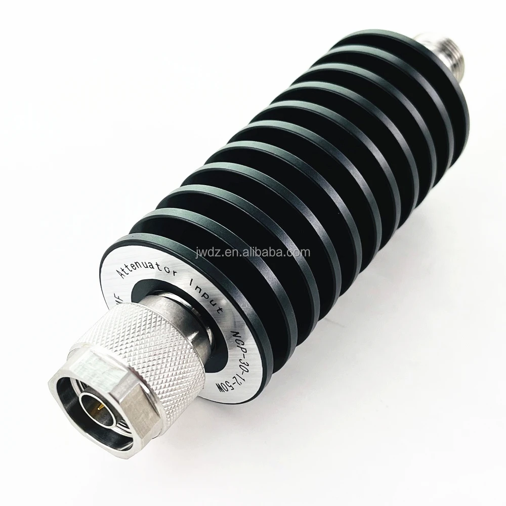
RF coaxial cables get their dependability from how they're built layer by layer with precision engineering. Inside we find either solid or stranded copper conductors that carry signals efficiently. Between these sits what's called a dielectric insulator material like PTFE or sometimes foamed polyethylene which keeps things running smoothly without interference. Then there's the shielding part usually made from braided copper or aluminum foil that blocks out about 90 to 95 percent of electromagnetic interference. And finally wrapped around everything is an outer jacket typically made of UV resistant PVC to protect against weather and other environmental factors. Real world testing has found that these multi layered designs actually fail much less often than simpler single layer options about 25% less frequently according to field data collected over time.
The latest generation of RF coaxial cables is making waves thanks to some serious innovations in materials science that help them keep up with what 5G networks demand. When it comes to conductivity, high purity copper alloys are cutting down on signal loss by around 18% when compared to regular conductors according to a study published by Ponemon back in 2023. Meanwhile, those fancy nitrogen injected foamed dielectrics inside these cables have managed to boost their velocity factor to about 0.85, which means signals can travel through them much quicker than before. The outer layer isn't getting overlooked either. Dual layer irradiated polyethylene jackets are holding up against harsh weather conditions about 40% better than older models, so these cables last well over 15 years even in tough city environments where temperature extremes are common. All these improvements line up nicely with what we saw in the 2024 Telecommunications Materials Report, where experts pointed out that upgrading materials isn't just nice to have but absolutely essential if carriers want to maintain that near perfect 99.999 percent network uptime everyone's counting on.
A 50 ohm impedance standard helps cut down on those annoying signal reflections because it keeps the dielectric constant really stable within about 1.5% variation. When engineers get this wrong in the field, things go south fast. We've seen from testing that mismatched impedances can boost return loss by as much as 6 decibels, which causes problems in roughly four out of five base station setups according to New England Labs research last year. Modern production techniques now maintain conductor alignment within less than 0.1 millimeters apart. This matters a lot when cables need to bend at right angles without losing their performance characteristics. The result? Much better signal quality with around 32 percent less phase distortion at those high mmWave frequencies compared to what happens with cables made outside these standards.
| Factor | Corrugated Copper | Aluminum |
|---|---|---|
| Conductivity | 100% IACS | 61% IACS |
| Weight | 8.96 g/cm³ | 2.70 g/cm³ |
| Corrosion Resistance | Excellent (with coating) | Good (anodized variants) |
| Flexibility | 30% higher bend cycles | 15% higher stiffness |
Copper is preferred for high-power urban macrocell deployments, while aluminum's 63% weight reduction makes it ideal for aerial installations. Corrugated designs enhance crush resistance by 22% in both materials compared to smooth-walled alternatives.
Today's base stations have to deal with all sorts of electromagnetic clutter coming from nearby antennas, power lines running everywhere, plus countless IoT gadgets buzzing around. The solution? RF coaxial cables with good shielding do wonders here. These cables act as barriers against unwanted radio frequency noise that would otherwise disrupt signals. According to some recent research published in the 2024 RF Shielding Effectiveness Report, when operators invest in quality shielding materials, they see a dramatic drop in service interruptions caused by interference. In busy city areas where electromagnetic interference (EMI) can hit over 100 volts per meter, these improvements cut down on problems by nearly two thirds. That makes a huge difference for maintaining reliable communications in crowded urban settings.
To combat high-frequency EMI in 5G bands, manufacturers use layered shielding architectures combining foil, braid, and composite materials:
| Shield Type | Frequency Coverage | EMI Attenuation (dB) | Flexibility |
|---|---|---|---|
| Single Braid | Up to 6 GHz | 40 50 dB | High |
| Foil + Braid | Up to 40 GHz | 70 85 dB | Moderate |
| Quadruple Shields | 60 GHz+ | 90 110 dB | Low |
Multi-layer designs outperform single-shield cables by 2.5× in mmWave bands, based on a comparative shielding study analyzing 120 cellular sites.
While shielding improves EMI resistance, improper termination can lead to passive intermodulation (PIM), where corroded connectors or loose junctions generate unwanted signals. Industry studies show 31% of field failures in dense networks stem from PIM rather than shield defects, underscoring the importance of precision assembly.
In 2023 trials, deploying double-shielded RF coaxial cables in macrocell base stations reduced EMI-related retransmissions by 42%. Networks using 90 dB-shielded cables achieved 12% higher signal-to-noise ratios than those with standard 60 dB designs, demonstrating their effectiveness in high-interference zones such as stadiums and transportation hubs.
RF coaxial cables maintain consistent performance throughout the entire frequency range found in today's base stations, covering everything from the sub-6 GHz bands around 3.3 to 7.1 GHz all the way up to those high frequency mmWave ranges between 24 and 40 GHz. These cables have special materials inside that minimize signal loss and maintain that exact 50 ohm resistance needed for transmitting power efficiently even when dealing with powerful signals reaching up to 5 kilowatts in big cell tower setups. When it comes specifically to mmWave applications, manufacturers are increasingly turning to nitrogen filled foam polyethylene insulation instead of regular PTFE material. According to recent findings published last year in the Wireless Infrastructure Report, this change actually cuts down on signal loss by about 17 percent, making these cables much better suited for handling those challenging higher frequency transmissions.
In urban environments handling over 50,000 simultaneous connections, double-shielded RF coaxial cables maintain 98.6% signal integrity under peak loads. Their bend-resistant construction allows compact routing in cable trays and towers offering a distinct advantage over rigid waveguide solutions.
More and more network operators are turning to wideband RF coaxial cables that work across the 1.7 to 7.5 GHz range. These cables let them combine their 4G, 5G, and LTE networks all on one single feeder line instead of multiple ones. The cost savings from this setup can be pretty significant too, around 23 percent according to the Mobile Broadband Alliance report from 2023. Plus it leaves room for growth since these systems can handle frequencies up to 10 GHz in the future. Looking even further ahead, there's something interesting happening with hybrid cable designs that use air spaced dielectrics. These new cables are starting to show up in applications needing ultra wideband mmWave backhaul connections above 28 GHz frequencies.
What are RF coaxial cables used for?
RF coaxial cables are used for transmitting radio frequency signals in telecommunications infrastructure, including cellular networks and base stations.
Why are coaxial cables preferred over fiber for last-mile connections?
Coaxial cables are preferred over fiber in last-mile connections due to their cost-to-performance ratio and weather resistance.
What frequency range do RF coaxial cables cover?
RF coaxial cables cover a frequency range from DC to 110 GHz, making them suitable for various applications.
What is the impact of improper termination on RF coaxial cables?
Improper termination can lead to passive intermodulation (PIM), causing unwanted signals and reducing reliability.
How do shielding designs affect performance in dense RF environments?
Shielding designs with multiple layers (foil, braid, composite materials) reduce interference issues and improve EMI resistance in dense RF environments.

Copyright © 2024 by Zhenjiang Jiewei Electronic Technology Co.,Ltd - Privacy Policy
 Hot News