
Leaky Cable Fundamentals: Radiation Mechanism and Passive DAS Integration
Radiating vs. coupled mode operation for uniform indoor signal distribution
Leaky cables provide reliable indoor coverage using two main operating methods: radiating and coupled modes. When working in radiating mode, these cables have specially designed slots cut into their outer layer that release radio frequency signals throughout the entire cable run. This works great for long straight runs such as corridors, underground passages, and building staircases. The other mode called coupled mode functions differently. Instead of emitting signals directly, it uses electromagnetic fields to interact with nearby antennas or metal surfaces, allowing signals to reach places that are otherwise difficult to access without actually broadcasting from the cable itself. This combination of both approaches explains why leaky cables form such an important part of many distributed antenna systems installed in complicated buildings. Take sports arenas for instance. They often install radiating cables around the edges of spectator seating areas but then branch out with coupled mode sections to reach luxury boxes and food courts where standard antenna setups would leave big gaps in service. Tests done in real world conditions show that combining these technologies can boost signal strength consistency by somewhere around 40 percent in buildings made from multiple materials that block signals.
Physics of controlled leakage: slot geometry, corrugation design, and coupling loss tuning
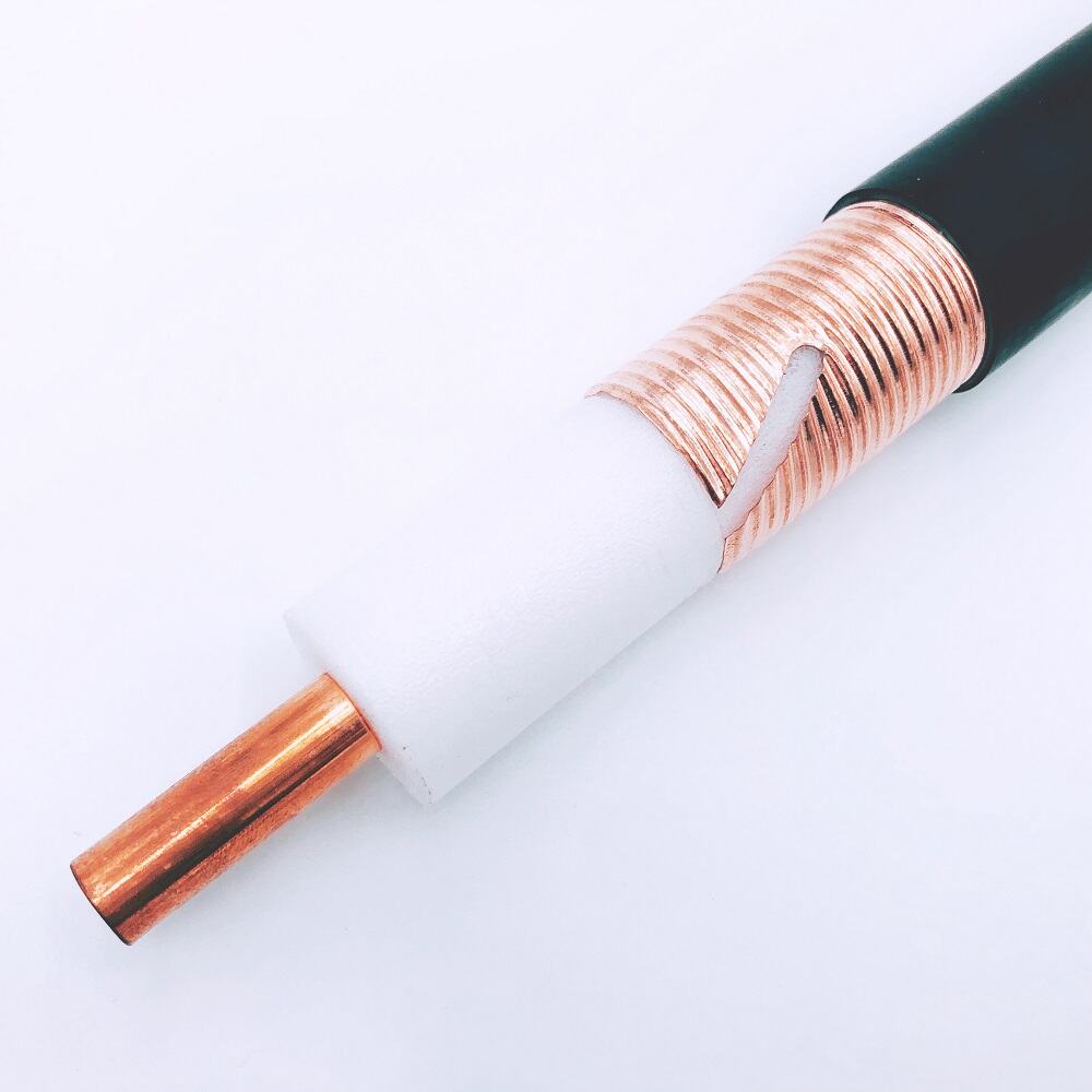
RF leakage control isn't something that happens by chance. It comes down to careful electromagnetic engineering work. There are basically three factors that work together to affect how well these systems perform: the shape of the slots, the way the inner conductor is corrugated, and getting the right impedance match. The actual slot shapes can be either elliptical or rectangular, spaced usually around a quarter to half wavelength apart, and positioned in specific orientations that dictate things like radiation patterns, what frequencies get selected, and how far signals spread out. When conductors inside have those corrugations, they help stop unwanted higher order modes and make those annoying impedance jumps much less problematic. This cuts down on signal loss by about 15 to 20 decibels every 100 meters compared to regular smooth conductor versions according to waveguide theories backed up by standards organizations like IEEE and IEC. The amount of coupling loss, which basically measures how much signal gets transferred from the cable into surrounding areas, depends heavily on slot density too. If there are fewer slots per meter (say 2 to 4), the signals penetrate better through tough stuff like reinforced concrete walls. More slots (around 6 to 8 per meter) give better coverage over larger open spaces. Take helical corrugation designs as an example—they let signals work across a broad range from 698 MHz all the way up to 3.8 GHz while keeping radiation efficiency above 85% throughout that whole spectrum.
Multi-Band Performance: Supporting Cellular, Wi-Fi, and Broadcast Services Simultaneously
Frequency-Agile Leaky Cable Designs Covering 700 MHz to 3.8 GHz
Today's leaky cables aren't just about wide bandwidth anymore; they're built for real multi-service convergence where different signals can live together without causing trouble. The magic happens thanks to carefully designed slot shapes and those fancy corrugation patterns on the cable surface. These allow everything from 700 MHz signals used by FirstNet and digital TV broadcasts right up through sub-6 GHz 5G networks and even reaching 3.8 GHz frequencies. That covers pretty much every important band out there including cell phone networks, public safety communications, Wi-Fi 6/6E at 5 GHz, and old school broadcast channels too. When engineers choose between straight slots running the length of the cable or spiral shaped ones wrapped around it, they actually adjust how much signal leaks out. This helps keep radiation levels within about 1.5 dB difference across all those different frequencies. And this small window makes a big difference in places crowded with wireless signals like busy train stations or tall apartment complexes where regular antennas would need complicated filters and separation techniques to work properly.
Real-World Coexistence Validation: LTE-A, 5G NR, Wi-Fi 6, and DVB-T in Mixed-Use Buildings
Testing in actual environments backs up what theory suggests. Steel framed buildings used for retail and commercial spaces saw leaky cables handling multiple signals at once. These included LTE-A on 2.1 GHz, 5G NR at 3.5 GHz, Wi-Fi 6 operating around 5 GHz, plus DVB-T signals at 700 MHz. The system maintained stable connections across all these frequencies with just under 1.3% signal drop overall. What makes this work so well is how the cable leaks signals selectively based on controlled wave patterns instead of broadcasting everything equally. This prevents different services from interfering with each other. Even when cell networks got busy, Wi-Fi connections lost less than one tenth of a percent of data packets. Broadcast videos kept playing smoothly while people made voice over LTE calls nearby. Traditional setups need separate antennas, cables, filters, and power boosters for each service type. But this single solution cuts down on equipment needs by roughly 40% and saves money during installation. Maintenance becomes easier too, and adding new capabilities later doesn't require tearing everything apart.
Dead Zone Elimination: Penetration and Coverage Reliability in Challenging Indoor Environments
Signal resilience through reinforced concrete, structural steel, and low-emissivity glass
Modern construction materials like reinforced concrete, structural steel frames, and those fancy low-e glasses are pretty good at stopping radio frequency signals, sometimes creating losses between 20 to 40 dB. We see these signal blockages all the time in places such as elevators, underground areas, medical imaging rooms, and those super efficient office buildings with their sleek exteriors. Leaky cables tackle this problem differently than just cranking up power levels. Instead they move the radiation point right into where the obstacles are. The way these cables work is pretty clever actually their straight line emissions manage to get around reflective surfaces and connect well with nearby areas. Since the signal spreads out along the whole length of the cable, it stays strong and consistent across different spaces even when going through thick walls. Field tests have shown that leaky coax cables maintain less than 3 dB loss when passing through 40 cm thick concrete walls, which beats regular ceiling mounted antennas by about 15 dB under similar circumstances.
Case study: Achieving 99.2% coverage uniformity across a 12-floor hospital with dual-band leaky coax
An urban hospital with 12 stories recently installed dual band leaky cable systems to fix serious communication problems in critical areas like MRI rooms, underground parking garages, and radiation protected labs. The installation managed both FirstNet at 700 MHz and newer 5G NR signals at 2.5 GHz frequencies through one coaxial setup. After putting it all together, tests showed that 99.2% of the building had consistent coverage. Signal strength readings came in above -95 dBm throughout every floor and department, even reaching spots where there used to be absolutely no reception before. When emergency crews tested the system during actual drills, they found their radios worked flawlessly with only minor issues during transitions between different cable sections. What makes this solution stand out is how well it performs compared to traditional methods. Proper planning around building architecture and understanding frequency behavior lets hospitals achieve reliable communications standards that older passive or active distributed antenna systems simply cannot match.
FAQ
How do leaky cables work?
Leaky cables operate using radiating and coupled modes. Radiating mode emits signals directly through slots in the cable, while coupled mode uses electromagnetic fields to transmit signals without direct emissions.
What is the advantage of leaky cables in complicated buildings?
Leaky cables can enhance signal strength and consistency, especially in buildings made from materials that typically block signals, boosting reliability by around 40%.
What materials and features in leaky cable design help reduce signal loss?
The shape of the slots, corrugation design of the inner conductor, and slot density are crucial. These factors help manage radiation patterns, frequency selection, and limit signal loss.
How do leaky cables support multiple services like cellular and Wi-Fi?
Leaky cables use frequency-agile designs that accommodate a range of frequencies (700 MHz to 3.8 GHz), supporting diverse services simultaneously without interference.
Can leaky cables help improve coverage in areas with structural challenges?
Yes, by positioning radiation points within obstacles, leaky cables ensure strong signal distribution even through material barriers like concrete and steel.
Table of Contents
-
Leaky Cable Fundamentals: Radiation Mechanism and Passive DAS Integration
- Radiating vs. coupled mode operation for uniform indoor signal distribution
- Physics of controlled leakage: slot geometry, corrugation design, and coupling loss tuning
- Multi-Band Performance: Supporting Cellular, Wi-Fi, and Broadcast Services Simultaneously
- Dead Zone Elimination: Penetration and Coverage Reliability in Challenging Indoor Environments
- Signal resilience through reinforced concrete, structural steel, and low-emissivity glass
- Case study: Achieving 99.2% coverage uniformity across a 12-floor hospital with dual-band leaky coax
- FAQ