
Key RF Connector Types and Their High-Frequency Performance Profiles
SMA, 2.92mm, 2.4mm, and SMP Connectors: Frequency Limits, Repeatability, and Use Cases
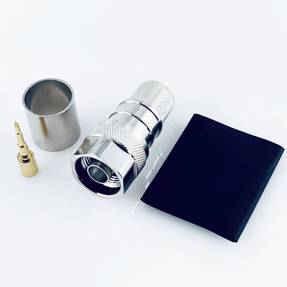
SMA connectors are still going strong in those sub-18 GHz applications we see everywhere from cell towers to radio systems because they hold up well and don't cost too much money. The downside? Those threads on them start wearing out after about 500 times connecting and disconnecting, which makes repeated connections less reliable over time. When things need to work at higher frequencies though, engineers turn to different options. The 2.92mm connector (sometimes called K-connector) handles frequencies all the way up to 40 GHz while the smaller 2.4mm version pushes even further to around 50 GHz. These connectors use air instead of solid materials between conductors and have much tighter manufacturing specs, so they lose less signal strength and maintain better electrical continuity throughout the connection. Then there's the SMP connector family with those sliding spring loaded contacts that just snap right on. They take up less space and can rotate completely around, making them great for crowded phased array setups where space matters. These will reliably handle signals at 40 GHz too. But watch out for one thing: those flexible contact points actually create more signal loss than the stiffer precision connectors, roughly 0.3 dB extra at 30 GHz according to measurements.
Precision Air-Dielectric (e.g., APC-7) and BMAM Connectors: Phase Stability and Bandwidth Advantages Above 40 GHz
When operating above 40 GHz frequencies, air dielectric connectors such as the APC-7 series remove issues related to PTFE material causing phase instability, achieving impressive amplitude consistency within ±0.05 dB all the way up to 110 GHz. The design's absence of beads helps reduce those annoying impedance jumps, keeping voltage standing wave ratio under 1.05 even at 50 GHz levels. For applications needing extended performance, BMAM connectors take things further with their special fused hermetic seals that stop oxidation problems - something absolutely essential when dealing with satellites that need thousands of connection cycles. These advanced interfaces allow synchronized operation across multiple ports in modern radar setups, where phase tracking stays remarkably accurate at just 0.5 degrees deviation at 70 GHz. Tests according to IEEE MTT-S standards show they beat polymer filled options by roughly 40% when it comes to maintaining stability over time.
Critical RF Connector Selection Criteria for Millimeter-Wave Systems
Selecting RF connectors for millimeter-wave systems (frequencies > 30 GHz) demands rigorous validation against three electromagnetic performance risks:
- Cutoff behavior: Connector dimensions must suppress higher-order modes. At 40 GHz, a 2.92mm connector's theoretical cutoff is ~46 GHz—but manufacturing tolerances can trigger premature mode excitation, degrading signal fidelity.
- Harmonic distortion: Non-linear contact interfaces generate spurious signals at integer multiples of the fundamental frequency. Gold-plated beryllium copper contacts reduce intermodulation distortion by 15 dBc versus silver-plated brass, preserving spectral purity.
- Dielectric resonance: Polymer insulators exhibit resonant absorption peaks above 26 GHz. Air-dielectric designs eliminate this mechanism entirely, sustaining VSWR <1.15 up to 50 GHz.
Insertion Loss Drivers: Conductor Material, Surface Roughness, and Geometric Scaling Effects on RF Connector Loss
Insertion loss in millimeter-wave RF connectors scales nonlinearly due to three dominant factors:
- Conductor resistivity: Oxygen-free copper (Î = 58 MS/m) reduces skin-effect loss by 22% versus brass at 60 GHz.
- Surface roughness: RMS roughness exceeding 0.4 µm increases loss by 0.05 dB/cm at 40 GHz; mirror-polished contacts maintain <0.01 dB degradation per connection.
- Geometric discontinuities: A 5 µm center conductor misalignment induces 0.2 dB additional loss at 50 GHz due to current crowding—highlighting the need for hyperbolic or corrugated contact geometries.
Frequency Range Validation: Cutoff Behavior, Mode Suppression, and Harmonic Risks Beyond 26 GHz
Phase-stable operation above 26 GHz requires tight control over three parameters:
- Impedance tolerance: Maintaining 50 Ω ±0.5 Ω limits VSWR-induced reflections. Standard SMA connectors exceed ±2 Ω tolerance above 18 GHz, making them unsuitable for mmWave use.
- Return loss: A specification of >20 dB prevents standing waves in test setups; precision connectors achieve >26 dB up to 40 GHz.
- Thermal drift: Î VSWR <0.05 across −55°C to +125°C ensures consistent performance in radar and aerospace environments.
Impedance Integrity and VSWR Control in High-Frequency RF Connector Interfaces
Tolerance Stack-Ups, Center Contact Alignment, and Return Loss Degradation Above 20 GHz
Keeping impedance stable gets really tough once we hit frequencies above 20 GHz. At these high levels, even tiny mechanical changes at the micron scale can mess up the Voltage Standing Wave Ratio (VSWR) significantly. When there's a 5 ohm mismatch between parts, it actually boosts signal reflections by around 40% in those millimeter wave systems. Something else worth noting is center conductor alignment issues. If they're off by more than 0.05 mm, which happens quite often due to all those tolerances stacking up over time, return loss drops between 3 to 6 dB at 40 GHz. This translates to real problems like power losses and phase distortions that become absolutely critical for proper operation of phased array antennas.
Precision alignment techniques mitigate these effects:
- Hyperbolic contact profiles reduce VSWR to below 1.15:1
- Corrugated interfaces demonstrate 18% better thermal stability during cycling from −40°C to +85°C
- Minimized air gaps prevent dielectric-induced impedance shifts
Above 30 GHz, surface roughness dominates loss behavior. Contacts polished to <0.1 µm Ra sustain insertion loss below 0.1 dB per connection. Without such controls, VSWR exceeding 1.5:1 reflects >4% of transmitted power—severely degrading error vector magnitude (EVM) in 256-QAM modulated signals.
Cable-to-RF-Connector Integration: Minimizing Discontinuities and Reflections
Getting the connection right between cables and RF connectors matters a lot when it comes to keeping signals clean in those high frequency systems we work with daily. Even tiny impedance mismatches around 5 ohms can cause signal reflections that jump up to 40%. These reflections really mess with EVM measurements on modulated signals. The problem gets worse at mmWave frequencies because the wavelengths are so short. What might seem like a minor break in continuity becomes a major source of signal scattering at these higher frequencies. Engineers need to watch out for this since proper connector installation makes all the difference in system performance. When dealing with these challenges, there are several approaches engineers typically take to reduce unwanted reflections.
- Maintain strict 50Ω impedance continuity across all interfaces
- Target VSWR <1.2:1, especially in massive MIMO base stations where cascaded mismatches compound
- Employ corrugated conductors, which deliver 18% better thermal stability than smooth alternatives over −40°C to +85°C cycling
Precision alignment of center contacts and dielectric support structures prevents return loss degradation beyond 20 GHz. Industry analysis attributes nearly one-third of urban 5G latency issues to coaxial line mismatches—underscoring that optimal integration combines geometric consistency with materials engineered for minimal surface roughness and suppressed parasitic mode excitation.
FAQ Section
-
What is the main disadvantage of SMA connectors?
The main disadvantage of SMA connectors is that their threads wear out after about 500 times of connecting and disconnecting, making repeated connections less reliable over time.
-
Why are air dielectric connectors preferred above 40 GHz?
Air dielectric connectors, like the APC-7 series, are preferred above 40 GHz because they eliminate phase instability issues and maintain impressive amplitude consistency, reducing impedance jumps for better performance.
-
What factors contribute to insertion loss in millimeter-wave RF connectors?
Insertion loss in millimeter-wave RF connectors is influenced by conductor resistivity, surface roughness, and geometric discontinuities.
-
How do engineers minimize signal reflections in high-frequency systems?
Engineers minimize signal reflections by maintaining strict 50Ω impedance continuity, targeting VSWR <1.2:1, and using corrugated conductors for better thermal stability during cycling.
-
Why is center contact alignment critical above 20 GHz?
Center contact alignment is critical above 20 GHz because misalignments can significantly degrade return loss, causing power losses and phase distortions essential for phased array antenna operation.