
Understanding the Role of Feeder Cable in Base Station Performance
The Critical Function of Feeder Cable in RF Signal Transmission
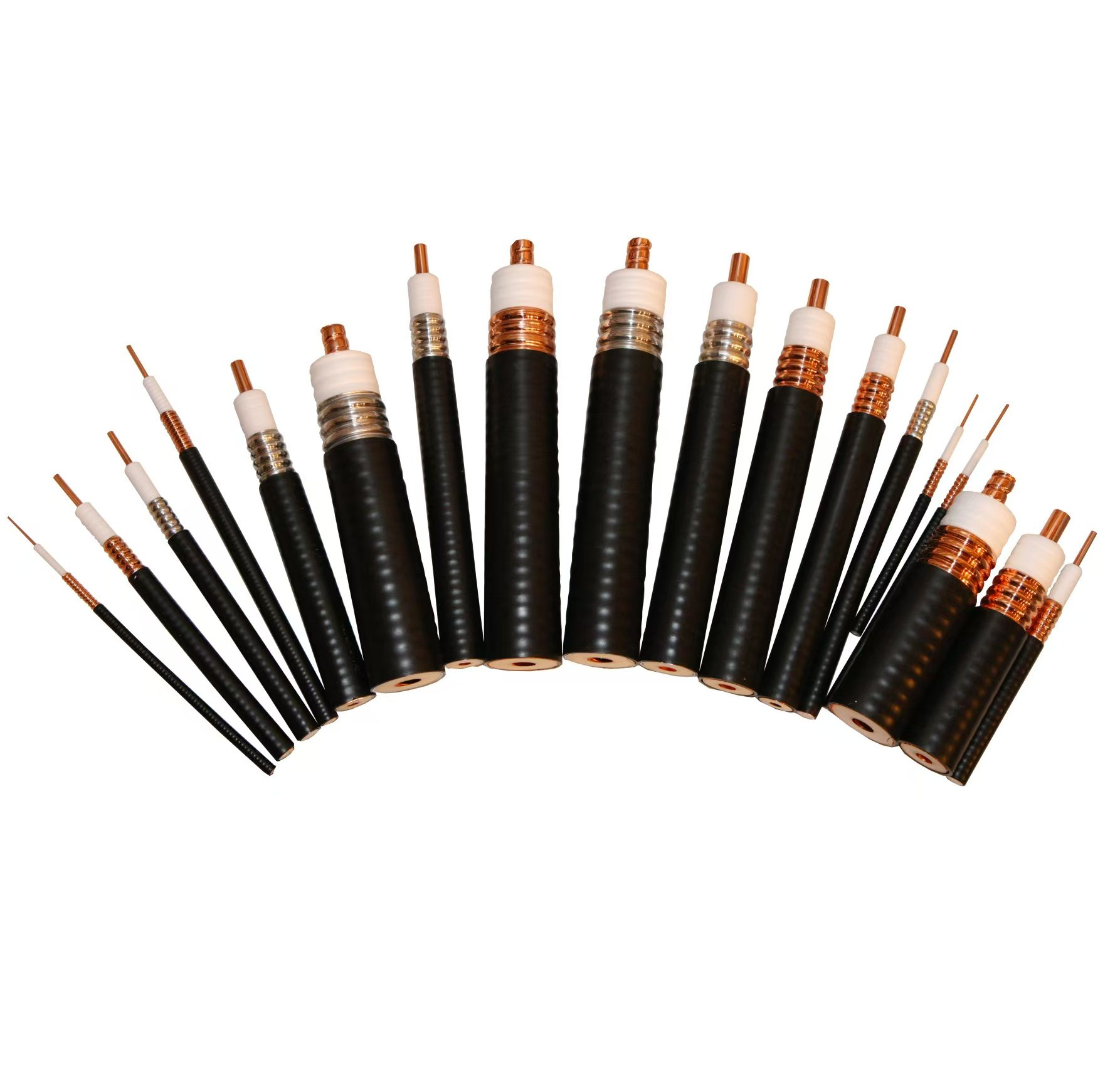
Feeder cables play a crucial role in keeping RF signals intact within mobile base stations. They carry those high frequency signals from radios to antennas while trying to keep losses to a minimum. Most of these coaxial cables stick to the standard 50 ohm impedance because anything different causes reflections that mess up network performance. The math gets interesting when looking at connector losses too. Take a 0.3 dB hit at each connector and multiply that across four ports in a system, suddenly we're talking about a total loss of around 2.4 dB. That kind of cumulative effect really eats into signal strength right where it matters most at the antenna connection point.
Impact of Feeder Cable Integrity on Base Station Performance Testing
When cables develop problems, they really mess with important performance numbers such as Voltage Standing Wave Ratio (VSWR) and what's called return loss. Field tests from last year showed something interesting: out of all those base stations where VSWR went over 1.5:1, about two thirds actually had issues with their feeder cables. This wasn't just a minor problem either - it was causing network speeds to drop by around 15% in mid band 5G systems. Old cables are becoming another big headache too. Signals traveling through microwave frequencies above 3 GHz get weakened much more in older setups than fresh installations show roughly 23% greater signal loss. That's why checking these cables regularly makes so much sense for maintaining good network performance.
Common Failure Modes: Moisture Ingress, Connector Corrosion, and Physical Damage
Three primary failure mechanisms compromise feeder cable reliability:
- Moisture ingress (38% of failures): Leads to impedance mismatches and dielectric breakdown
- Connector corrosion (29%): Increases insertion loss by up to 1.2 dB at mmWave frequencies
- Physical damage (22%): Kinks or compression alter waveguide behavior, creating standing waves
To mitigate these risks, preventive maintenance should include quarterly inspections using time-domain reflectometry (TDR) to detect early-stage degradation before it impacts service availability.
Key Indicators of Feeder Cable Signal Degradation
Mobile network engineers must monitor critical parameters to identify feeder cable degradation before it affects base station performance.
Signal Loss Mechanisms in Long Feeder Cable Runs
As frequency goes up and distance increases, so does signal attenuation. For instance, standard coaxial cables see around 0.25 dB loss per meter at 2.4 GHz frequencies. Things get even trickier with millimeter waves between 24 and 40 GHz, where signal loss is roughly triple what we see in sub-6 GHz bands. This makes picking the right cables absolutely critical when rolling out 5G infrastructure. Environmental factors don't help matters either. Changes in temperature and exposure to moisture can really speed up equipment degradation over time. And let's not forget about connectors, which are responsible for anywhere from 15% to 30% of all signal loss in most installations according to field experience.
Return Loss and VSWR Measurements as Indicators of Impedance Mismatch
VSWR values above 1.5:1 indicate impedance mismatches at connectors or bends, a major source of reflected power. Field technicians use handheld analyzers to assess cable health based on established thresholds:
| Measurement Type | Optimal Threshold | Critical Alert Level |
|---|---|---|
| VSWR | <1.3:1 | >1.8:1 |
| Return Loss | >20 dB | <15 dB |
A 2023 audit showed that 68% of degraded feeder cables exhibited abnormal VSWR readings before visible physical damage occurred.
Case Study: 30% Signal Drop Due to Undetected Feeder Cable Fault in Urban 5G Node
In a high-density urban 5G deployment, download speeds dropped from 800 Mbps to 560 Mbps. Initial diagnostics pointed to radio configuration errors, but physical-layer testing revealed:
- 18 dB insertion loss due to water ingress at tower base connectors
- VSWR spike to 2.1:1 at 28 GHz
- Intermittent resistance fluctuations (0.8–5.6 Ω)
Replacing the corroded feeder cable restored full performance within two hours, preventing an estimated $8,000 in revenue loss from prolonged service degradation.
Trend: Increasing Sensitivity to Feeder Cable Stability in mmWave 5G Deployments
Millimeter-wave 5G systems demand 40% tighter feeder cable tolerances than 4G. According to the 2024 Mobile Infrastructure Report:
- 55% of mmWave sites require monthly VSWR verification, compared to quarterly checks for sub-6 GHz systems
- Temperature-induced phase variations account for 22% of beamforming alignment errors
- Predictive models now combine real-time strain gauges with historical weather data to forecast cable faults
Operators using these advanced monitoring techniques have reduced feeder-related outages by 73% since 2022.
Core Testing Methods for Feeder Cable Reliability
Fundamentals of Return Loss and VSWR Measurements
Return loss quantifies reflected energy at impedance discontinuities, with mission-critical base stations typically requiring better than -20 dB performance. VSWR testing identifies mismatches, where ratios exceeding 1.5:1 suggest potential signal degradation (Telecommunications Industry Association 2023). Modern test equipment integrates automated pass/fail thresholds to streamline field assessments of feeder cable integrity.
Frequency Domain Reflectometry for Fault Location in Feeder Cable
Frequency Domain Reflectometry (FDR) precisely locates faults by analyzing signal reflections across frequency bands. Recent trials show FDR can pinpoint moisture ingress within ±0.3 meters in coaxial cables up to 150 meters long (Wireless Infrastructure Association 2023). This method is particularly effective for detecting intermittent faults that evade traditional time-domain testing.
Baseline vs. Real-Time Performance: Setting Acceptable Thresholds
Performance baselines must consider cable length, frequency band, and environmental conditions. For urban 5G deployments, experts recommend real-time monitoring systems that trigger alerts when attenuation exceeds initial values by 15% (ETSI TR 103 451 2022). Adaptive threshold algorithms now adjust for temperature-induced variations, reducing false-positive maintenance dispatches by 22% compared to static thresholds.
Best Practices for Field Testing Feeder Cables with Handheld Analyzers
Step-by-Step Pre-Installation and Post-Installation Cable Validation
Begin with a visual inspection for physical damage or connector deformation. Conduct pre-installation tests including continuity checks and baseline VSWR measurements across the operating frequency range. After installation, verify performance using distance-to-fault (DTF) analysis and compare results to pre-installation data to detect stress-induced distortions or bending losses.
Calibrating Handheld Analyzers for Accurate Diagnostics
Calibration must account for environmental effects on dielectric properties. Use open/short/load (OSL) calibration kits matched to the analyzer’s frequency range. For mmWave 5G systems, calibrate at multiple points between 24 GHz and 40 GHz to ensure dynamic range accuracy and measurement reliability.
Comparative Analysis of Industry-Leading Test Tools
High-end handheld analyzers differ in precision and efficiency. Some offer ±0.5 dB amplitude accuracy for return loss, while others provide faster frequency sweeps for long cable runs. Prioritize models with adaptive pass/fail thresholds that adjust automatically based on cable length and frequency band to improve diagnostic consistency.
Minimizing Human Error During Field Testing
Implement dual-verification workflows where two technicians independently validate critical measurements. Use analyzers with guided test sequences to standardize probe placement and connector torque. For complex sites, record environmental conditions like temperature and humidity alongside measurement data to help isolate external interference sources.
Advanced Integration: Combining Physical and Network Layer Testing for Feeder Cable Validation
Complementary Role of Spectrum Analyzers in Verifying Signal Strength and Coverage Testing
Spectrum analyzers really boost physical layer testing because they pick up on signal leaks that standard VSWR measurements often overlook. According to some recent research, these devices catch interference problems in about 15 out of every 100 5G mmWave installations. This helps techs find those trouble spots where signals drop off due to poor shielding around equipment. Combine this with GPS information and suddenly field engineers can pinpoint exactly which cables are causing coverage issues. Most technicians swear by this method when troubleshooting tricky installation problems in real world conditions.
Using Protocol Analyzers to Correlate Feeder Cable Stability with Network Layer Performance
Looking at protocol analyzers shows us that small problems with feeder cables can actually mess up higher layer performance quite a bit, even if all the physical measurements look fine on paper. Take this real world case study from Mobile Networks Quarterly back in 2025: just a half dB rise in cable loss led to an 18% jump in LTE retransmissions. Pretty shocking really. These days, newer diagnostic equipment connects TDR readings with actual packet captures, so we can now see exactly how something as simple as corroded connectors translates into real world latency issues at the application layer. Makes sense why network engineers are getting so serious about these seemingly minor cable problems.
Controversy Analysis: When Physical Layer Tests Don’t Match Protocol-Level Results
Field tests conducted in 2025 revealed something interesting: around 28 percent of base stations experienced network issues even though their VSWR readings were technically within acceptable limits (less than 1.5:1). What's going on here? Turns out many problems come down to how feeder cables behave when temperatures rise during heavy usage periods. Standard testing procedures just don't account for these real world conditions where heat affects cable properties differently than in controlled lab environments. The bottom line is that current testing methods miss critical factors affecting actual performance, which means operators need better ways to assess equipment under realistic operating conditions instead of relying solely on textbook specifications.
Strategy: Predictive Maintenance Using Historical Feeder Cable Test Data
Looking at performance data across a full year cuts down on those surprise service interruptions by around 42%, according to the Telecom Maintenance Report from 2025. The latest machine learning systems are being trained not just on standard return loss measurements but also environmental factors. These smart models actually spot potential corrosion problems as much as three months before they happen. This gives network engineers time to focus their efforts on cable runs located near saltwater environments or heavy industry zones where cables face the toughest conditions day after day.
FAQ
What is the role of feeder cables in base station performance?
Feeder cables play a critical role in transmitting RF signals from radios to antennas within mobile base stations, minimizing signal loss to ensure optimal network performance.
How do feeder cable problems affect base station performance?
Issues like voltage standing wave ratio (VSWR) disruptions and return loss can significantly degrade network speed and reliability, as seen in older cable setups that experience greater signal loss.
What are common failure modes in feeder cables?
Moisture ingress, connector corrosion, and physical damage are the primary failure modes, each contributing to impedance mismatches and increased signal degradation.
How can VSWR and return loss indicate feeder cable issues?
VSWR values above 1.5:1 and return loss below 15 dB are indicators of impedance mismatch, which lead to signal reflection and loss.
What testing methods are recommended for feeder cable reliability?
Tests like Frequency Domain Reflectometry (FDR) and Voltage Standing Wave Ratio (VSWR) measurements are essential for diagnosing faults and maintaining feeder cable reliability.
Table of Contents
- Understanding the Role of Feeder Cable in Base Station Performance
- Key Indicators of Feeder Cable Signal Degradation
- Core Testing Methods for Feeder Cable Reliability
- Best Practices for Field Testing Feeder Cables with Handheld Analyzers
-
Advanced Integration: Combining Physical and Network Layer Testing for Feeder Cable Validation
- Complementary Role of Spectrum Analyzers in Verifying Signal Strength and Coverage Testing
- Using Protocol Analyzers to Correlate Feeder Cable Stability with Network Layer Performance
- Controversy Analysis: When Physical Layer Tests Don’t Match Protocol-Level Results
- Strategy: Predictive Maintenance Using Historical Feeder Cable Test Data
- FAQ