
Superior Shielding and Noise Immunity in RF Coaxial Cables
Core Structure of RF Coaxial Cables
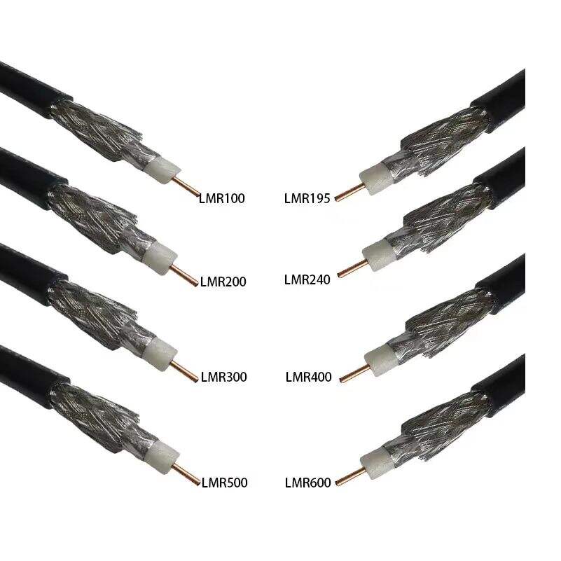
RF coaxial cables achieve noise resistance through a layered design: a central conductor surrounded by dielectric insulation, shielding, and an outer jacket. The dielectric layer minimizes electrical losses, while the shielding creates a Faraday cage to block external interference.
Shielding Effectiveness in Noisy Environments
Urban base stations face electromagnetic interference (EMI) from power lines, radio transmitters, and industrial equipment. Multi-layer shielding combats this by pairing 95% braid coverage for low-frequency noise with foil layers that reflect high-frequency EMI. Field tests show this dual-layer approach reduces interference by 40-60 dB compared to single-shield designs.
Multi-Layer Shielding and Interference Blocking
Advanced configurations use four shielding layers: two foil and two braided. The outer foil deflects airborne EMI, while the inner braid absorbs ground-loop currents. Spiral-braided variants improve flexibility without sacrificing coverage, which is critical for towers requiring frequent maintenance.
Braid Coverage and Dielectric Impact on Signal Clarity
Higher braid density provides 15-20% better noise rejection in congested spectrums. Low-loss dielectric materials like gas-injected foam polyethylene preserve signal integrity, reducing attenuation by 0.3 dB/m at 3 GHz.
Case Study: Urban Base Station Shielding Performance
A 2023 analysis of 200 urban sites found multi-shielded RF coaxial cables maintained 98.7% signal-to-noise ratio (SNR) compliance despite proximity to subway systems and 5G small cells. Sites using basic shielding required 33% more repeaters to meet SNR thresholds.
Low Signal Loss Over Long Distances with RF Coaxial Cable Design
Signal Loss in Coaxial Cables and Frequency-Dependent Attenuation
RF coaxial cables minimize signal degradation through precision engineering, with attenuation increasing directly with frequency. At 900 MHz, standard RG-8 cables lose 7.6 dB per 100 feet compared to 1.3 dB at 50 MHz, highlighting how higher frequencies accelerate energy dissipation as heat. This pattern necessitates frequency-based cable selection for base station applications.
Coaxial Cable Signal Loss (Per 10 Feet) by Gauge and Material
| Cable Type | 18 AWG (dB) | 14 AWG (dB) | Dielectric Material |
|---|---|---|---|
| Flexible Design | 0.35 | 0.22 | Gas-injected foam |
| Corrugated Copper | 0.28 | 0.15 | PTFE composite |
Thicker 14 AWG conductors reduce resistive losses by 37% compared to 18 AWG equivalents, while PTFE-based dielectrics maintain stable impedance across temperature fluctuations.
Low-Loss Flexible vs. Corrugated Copper Cables Comparison
When it comes to RF coaxial cables, the flexible ones give up about 0.07 dB per foot extra loss but gain something pretty valuable in return: they can bend all the way around at 180 degrees. This makes them great for those really cramped spaces on communication towers where installation is a challenge. Now corrugated copper versions work differently. These actually cut down on signal loss by roughly 0.13 dB per foot at 6 GHz frequencies because their outer conductors run without any breaks. For urban macro cell setups, many installers go with a mix of both types. They'll typically run the corrugated cables vertically through buildings since they handle temperature changes better within about 2 degree Celsius range. Then at the antennas themselves, they switch to those flexible jumpers we talked about earlier. Makes sense when considering how these systems need to perform reliably day after day.
Trend: Advanced Foam Dielectrics Reducing Insertion Loss
New research shows that these special low-PIM foam dielectrics can actually cut down on insertion loss quite a bit, somewhere around 26 to maybe even 30 percent when compared against regular old solid polyethylene cores. The air filled versions manage to keep their dielectric constants under 1.3, which is pretty impressive considering they still hold up against forces exceeding 500 Newtons before crushing. This performance makes them ideal for 5G NR rollouts since they help hit that important 3GPP standard of no more than 3 dB loss per 100 meters at frequencies hitting 28 GHz. Most top tier manufacturers are starting to adopt these graded index foams now because they work so well at minimizing those annoying modal dispersion issues that pop up in all sorts of wideband applications across different industries.
Impedance Stability and VSWR for Reliable RF Signal Transmission
Voltage Standing Wave Ratio (VSWR) and Impedance Stability Explained
RF coaxial cables keep signals strong by controlling impedance properly. The Voltage Standing Wave Ratio, or VSWR for short, basically measures how much signal bounces back when there's a mismatch in impedance. When everything matches perfectly, we get a 1:1 VSWR reading. Most modern cell towers actually run at around 1.4 to 1.5 ratio in practice. If things start going wrong and we see a 2:1 VSWR instead, about 11 percent of the power gets sent right back down the line instead of reaching where it needs to go. That kind of loss adds up fast over time, especially in large communication networks.
Maintaining 50-Ohm Impedance for Base Station Compatibility
Telecom companies have pretty much settled on 50 ohms as their go-to impedance standard for making sure RF coax cables work well with all those base stations out there. The reason behind this choice is pretty straightforward actually. It strikes just the right balance between how much power these cables can handle versus keeping signals clean and clear. Manufacturers achieve this sweet spot by carefully designing the conductor shapes and picking specific insulating materials. Recent improvements in what they call hexagonal braiding methods have made things even better. These new techniques cut down on inconsistencies during production which means less variation from cable to cable. As a result, most modern cables maintain that nice stable VSWR ratio around 1.3 to 1 across pretty much the entire frequency range from 600 MHz right up to 3.5 GHz frequencies. That kind of consistency makes life easier for engineers working on network installations.
Real-World Impact of Poor VSWR on Transmitter Efficiency
Looking at field data collected in 2024, we find that base stations where the VSWR goes over 2:1 tend to see about 22 percent more amplifier failures over a five year period. When there's reflected power in the system, the transmitters basically have to work harder, increasing their output by around 17% just to keep things running properly. This extra effort translates into real money too, with monthly energy bills going up approximately $74 for each urban cell site. Fortunately, newer adaptive impedance matching circuits are making a difference. These systems can keep the VSWR stable within plus or minus 0.05 even when temperatures swing wildly between -40 degrees Celsius and +85 degrees Celsius. That kind of stability makes all the difference in maintaining reliable network performance under challenging conditions.
Minimizing Intermodulation Distortion (PIM) in Passive RF Networks
Intermodulation distortion (PIM) in passive components overview
Passive Intermodulation Distortion, or PIM for short, happens when several high power RF signals meet inside passive components such as coaxial cables. These interactions create unwanted interference signals that mess up how well the network performs overall. Studies indicate that if transmit power goes up by just 1 dB, PIM increases by around 3 dB. This makes newer 5G installations particularly at risk since they operate across much broader frequency ranges. For today's LTE systems to work properly, PIM needs to stay below -169 dBc so receivers can still pick up signals down to -126 dBm sensitivity. Because of this requirement, manufacturers must follow very strict guidelines regarding materials used and construction methods for RF coaxial cables, especially important in crowded city areas where signal quality matters most.
Coaxial cable and PIM: How materials and joints contribute
Nonlinear effects at metal-to-metal contact points account for 78% of PIM cases. Key contributors include:
- Nickel-plated connectors, which exhibit 40% higher PIM than silver-plated variants
- Improperly corrugated cable shields causing interference spikes at 2.4 GHz and above
- Loose braid geometries leading to 15-20 dB PIM degradation compared to compression-molded designs
Controversy analysis: Are all low-PIM cables worth the cost?
While premium low-PIM cables reduce interference by 30-45 dB in lab settings, real-world benefits vary:
| Deployment Scenario | Standard Cable PIM | Low-PIM Cable Improvement | ROI Period |
|---|---|---|---|
| Urban macro cells | -120dBc | -150dBc (25% capacity) | 18 months |
| Rural small cells | -135dBc | -155dBc (8% capacity) | 5+ years |
This disparity fuels debate over cost-effective PIM thresholds for different deployment environments.
Industry paradox: High reliability vs. PIM sensitivity in dense networks
Efforts to achieve 99.999% uptime conflict with PIM physics; redundant cable paths increase metallic junctions by 60%, potentially raising PIM-related failure risks. As a result, modern base station designs prioritize centralized PIM monitoring over redundant hardware duplication.
Strategy: Mitigating PIM through installation best practices
Field studies confirm proper installation reduces PIM-related outages by 53%:
- Using torque-limiting wrenches for 35-40 in-lb connector tightness
- Performing bi-annual PIM sweep tests at 43 dBm transmit power
- Avoiding cable bends tighter than 4x the bend radius near antenna arrays
These protocols help maintain performance without mandating full low-PIM component replacements.
Frequency Range, Power Handling, and Environmental Durability
Frequency Range and Signal Integrity in Modern Baseband Units
RF coaxial cables support wide bandwidths essential for 5G and legacy systems, with modern base stations requiring operation from 600 MHz to 42 GHz. High-performance cables maintain <4 dB/100 ft attenuation at 6 GHz. Their design minimizes phase distortion, enabling simultaneous transmission of low-frequency control signals (1-3 GHz) and high-bandwidth millimeter waves (>24 GHz).
Power Handling Capacity of Coaxial Cables Under Continuous Load
Power handling depends on conductor size and dielectric stability. For example, ½-inch cables handle 300W continuous power (with 30% derating at 40°C), while 7/8-inch designs withstand up to 2000W peak loads. Key considerations include:
- Material limits: Copper-clad aluminum supports 150°C continuous operation
- Peak vs. average power: A 5:1 safety margin prevents dielectric breakdown during voltage spikes
Thermal Management in High-Power Outdoor Deployments
When setting up outdoor base stations, it's important to use cables that can handle extreme temperatures ranging from as cold as -55 degrees Celsius all the way up to 125 degrees Celsius. PTFE (polytetrafluoroethylene) jacketing keeps cables flexible even when temperatures drop below freezing point at around -40 degrees Celsius, plus it stands up well against damage from sunlight exposure over time. According to research conducted in 2023, using composite foil and braid shielding instead of just one layer actually cuts down internal temperatures inside equipment by about 18 degrees Celsius after running continuous load tests for three full days straight. For those really important setups where reliability matters most, engineers often pair forced air cooling solutions with industry standards like GR-487 which outlines how equipment should perform under different temperature cycles throughout their operational life span.
FAQ
-
What is the primary purpose of shielding in RF coaxial cables?
The primary purpose of shielding in RF coaxial cables is to block external interference, creating a Faraday cage effect around the central conductor. -
How does multi-layer shielding reduce interference in urban environments?
Multi-layer shielding reduces interference by combining high braid coverage for low-frequency noise rejection with foil layers that reflect high-frequency electromagnetic interference. -
Why are flexible cables preferred in certain installations?
Flexible cables are favored in cramped spaces where bending and maneuverability are necessary, while corrugated copper cables offer reduced signal loss and better temperature handling. -
What role do advanced foam dielectrics play in modern RF networks?
Advanced foam dielectrics minimize insertion loss, helping meet stringent standards like the 3GPP requirement for minimal loss in 5G networks. -
What is VSWR and why is it important?
VSWR, Voltage Standing Wave Ratio, measures signal reflection in an RF system. Proper impedance matching minimizes VSWR, ensuring efficient signal transmission. -
How does PIM affect passive RF networks and what measures can reduce its impact?
PIM causes interference by generating unwanted signals; effective measures include proper material selection, joint construction methods, and installation protocols.
Table of Contents
- Superior Shielding and Noise Immunity in RF Coaxial Cables
- Low Signal Loss Over Long Distances with RF Coaxial Cable Design
- Impedance Stability and VSWR for Reliable RF Signal Transmission
-
Minimizing Intermodulation Distortion (PIM) in Passive RF Networks
- Intermodulation distortion (PIM) in passive components overview
- Coaxial cable and PIM: How materials and joints contribute
- Controversy analysis: Are all low-PIM cables worth the cost?
- Industry paradox: High reliability vs. PIM sensitivity in dense networks
- Strategy: Mitigating PIM through installation best practices
- Frequency Range, Power Handling, and Environmental Durability