
Understanding RF Attenuation and Its Role in Signal Management
Definition of Attenuation in RF Coaxial Systems
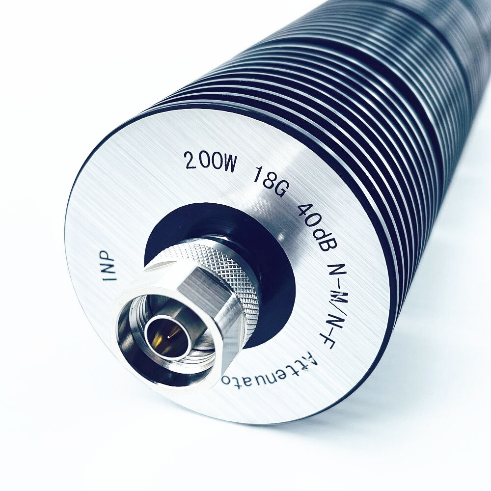
In RF coaxial systems, attenuation basically means reducing signal strength as it moves along transmission lines or components. We measure this drop in power using decibels (dB). The whole point is to keep signals at safe levels so they don't overload equipment downstream. This happens when energy gets lost in resistive parts of the system. Today's fixed attenuators do a pretty good job at cutting down those dB values exactly how we want them, plus they maintain proper impedance matching which matters a lot. Why? Because mismatched impedances cause reflections that mess up our signals. These modern devices work well across an impressive range too, handling everything from direct current all the way up to frequencies around 18 gigahertz without losing their effectiveness.
How Attenuation Values Affect Signal Strength and Integrity
The choice between 3dB, 6dB, or 10dB attenuation settings has a real impact on how well signals stand out from background noise and overall receiver function. Going for higher dB numbers does help shield delicate parts from getting overloaded, though engineers need to watch out for tradeoffs like increased insertion loss and heat issues. Take a 6dB cut for instance it basically cuts the signal strength in half. This matters quite a bit when working with those multi stage amplifier setups where we want to avoid unwanted distortion problems. Looking at what RF signal chain experts have been finding lately, too much power hitting the analog frontend just causes trouble. The result? Error vector magnitude measurements in 5G receivers drop around 40% based on recent waveform tests from last year.
The Impact of Power Attenuation on System Performance and Linearity
The power limits of commercial attenuators usually range from 1 to 100 watts, and these numbers tell us a lot about how linear the device stays when it's actually working hard. Getting the right amount of signal reduction is key for keeping distortion at bay. Some studies indicate that adding a 10 dB pad can boost those third order intercept points by around 15 dB in cable TV systems. Most engineers really care about temperature stability too. Even a small change of just 1 degree Celsius can throw off the attenuation reading by 0.02 dB. That might not sound like much, but in applications like millimeter wave radar calibration, where precision matters so much, those tiny shifts make all the difference between accurate readings and costly errors.
Standard Attenuation Values in Fixed Coaxial Attenuators
Common dB Levels: 3dB, 6dB, 10dB, and 20dB Explained
Fixed coaxial attenuators use standardized decibel (dB) values that balance system requirements with practical design. The most widely used levels are:
- 3dB: Halves input power, ideal for minor adjustments in impedance matching
- 6dB: Reduces power to 25% of initial levels, commonly used in antenna feedline balancing
- 10dB: Cuts power by 90%, frequently deployed in test equipment calibration
- 20dB: Limits output to 1% of input, essential for protecting sensitive receivers
A 2024 survey of RF system integrators found that 63% of installations use attenuators in the 3dB to 20dB range, aligning with industry-standard 50-ohm systems that emphasize minimal VSWR disruption.
Industry-Standard Value Progressions and Their Practical Use
Engineers select attenuation values based on logarithmic progressions that simplify cascaded signal chain designs. A typical sequence is:
Typical Progression
3dB → 6dB → 10dB → 20dB → 30dB
This allows cumulative reductions up to 69dB when combining multiple attenuators—sufficient for high-power radar and cellular infrastructure. Designs typically comply with ISO 9001:2015 thermal stability standards and support power handling up to 100W in compact N-type connectors.
N-Type 3dB Fixed Attenuators: Applications and Integration
N-Type 3dB attenuators are prevalent in base station deployments due to their rugged interfaces and 0.1dB amplitude flatness across 0–8GHz bands. Leading manufacturers optimize these for:
- Power amplifier output leveling in 5G mMIMO arrays
- VSWR correction in waveguide assemblies
- Signal path standardization during LTE/Sub-6GHz network upgrades
Field tests show 0.05dB insertion loss stability over temperatures from -55°C to +125°C, meeting MIL-STD-202G specifications for shock and vibration resistance.
Design and Engineering Factors Influencing Attenuator Performance
Resistive Network Topologies in Coaxial Attenuator Design
Coaxial attenuators rely on carefully designed resistive networks, mostly Pi (π) shapes or T-configurations, to reduce signals reliably. The Pi type works great with thin film resistors for about ±0.3 dB accuracy right up to 18 GHz frequencies. On the other hand, T networks can take much more power, handling as much as 200 watts continuously but they sacrifice some bandwidth capabilities. Designing these components is actually pretty tricky business. Engineers spend countless hours adjusting resistor materials and their physical arrangements to cut down on unwanted inductance effects. This careful work helps maintain flat signal loss performance with variations staying within ±0.1 dB across broad frequency spectrums, which matters a lot when dealing with complex communication systems.
Impedance Matching and VSWR Optimization for Signal Stability
When there's an impedance mismatch in RF systems, it creates those annoying standing waves that really mess up signal quality. The good news is high performance attenuators can keep VSWR ratios under control, typically maintaining them below 1.2:1 throughout their operating range thanks to balanced resistor configurations. Some studies have shown that adding a 6 dB attenuator cuts down on reflection problems by about half in standard 50 ohm systems, which protects delicate receiver components from getting damaged by back reflections. For even better results, newer advanced models manage to get VSWR down to less than 1.1:1 at frequencies going all the way up to 40 GHz. They accomplish this through clever design features like gradually shaped coaxial connections and spread out resistance components throughout the device.
Frequency Response and Bandwidth Limitations Across RF Systems
Modern fixed attenuators work across a pretty wide range, typically from DC right up to around 50 GHz. But there's a catch - their performance starts dropping off once they hit those material dependent cutoff points. Take the broadband 10dB models for instance. These can keep things pretty flat within ±0.5 dB all the way up to 26.5 GHz when using beryllium oxide substrates. However, push them to 40 GHz and we start seeing some issues with 1.2 dB of ripple caused by substrate mode excitation problems. That's where military grade versions come in handy. They solve these problems through special designs like evacuated coaxial structures paired with diamond heat spreaders. This combination allows operation from DC all the way through 110 GHz with impressive VSWR ratings down to 0.8:1. Such performance characteristics make them essential components for advanced systems like phased array radar setups and next generation 5G FR2 deployments where signal integrity really matters.
Key Applications of Fixed RF Attenuators in Real-World Signal Chains
Preventing Receiver Overload with In-Line Attenuation
Fixed RF attenuators protect sensitive receivers from high signal power. Inserting a 3dB or 10dB attenuator inline brings incoming signals within safe operating levels. In radar systems, where return pulses can overwhelm front-end components, a 6dB attenuator reduces power by 75%, enabling stable operation without sacrificing signal fidelity.
Signal Level Calibration in Test and Measurement Environments
Test instruments such as spectrum and network analyzers rely on fixed attenuators for accurate calibration. A 20dB attenuator simulates real-world cable losses, allowing precise power measurements. This practice follows MIL-STD-449D testing protocols, where ±0.2dB attenuation accuracy ensures repeatability across 5G and satellite communication systems.
Enhancing Impedance Match Accuracy Using Fixed Attenuators
Attenuators enhance impedance matching by damping reflected signals between mismatched components. A 3dB N-type attenuator improves VSWR from 1.5:1 to 1.2:1 in base station amplifiers, reducing standing waves that distort frequency response. This benefit is especially valuable in antenna arrays, where element-to-element impedance variations impair beamforming precision.
Case Study: Deploying 10dB Attenuators in Cellular Base Station Setups
In an urban 5G deployment, engineers installed 10dB fixed attenuators between power amplifiers and duplexers, achieving:
- 40% reduction in reflected power at 3.5GHz
- EVM improvement from 8% to 3% under full load
- 18-month extension in low-noise amplifier lifespan
The configuration maintained FCC Part 27 compliance while supporting 256-QAM modulation for higher data throughput.
Selection Criteria for Optimal RF Coaxial Attenuator Performance
Power Handling Capacity and Thermal Dissipation Efficiency
RF coaxial attenuators need to handle system power without messing up the signal quality. The power capacity varies quite a bit too - some can only take 0.5 watts for those quiet applications while others go all the way up to 1,000 watts in heavy duty setups according to Pasternack's data from last year. When dealing with these higher power levels, manufacturers typically build in aluminum heat sinks or sometimes even forced air cooling systems to keep things from overheating. Not getting this right can lead to problems like unwanted harmonics, strange intermodulation effects, or worse yet, actual physical damage to whatever circuits come after the attenuator in the system chain.
Connector Types (e.g., N-Type, SMA) and Environmental Durability
The type of connector selected makes a real difference when it comes to how well equipment performs and stays reliable over time. Two popular options are N-Type connectors which work up to around 18 GHz, and SMA connectors capable of handling frequencies all the way to 26.5 GHz. These connectors strike a good balance between what they can handle in terms of signal frequency and their physical durability. When dealing with tough conditions like those found at outdoor cell towers or on aircraft, engineers often turn to attenuators made with stainless steel casings and protected by IP67 sealing technology. Such designs stand up much better against environmental factors including water damage, dirt ingress, and temperature extremes ranging from minus 40 degrees Celsius right up to plus 125 degrees Celsius.
Frequency Band Compatibility in Modern 5G and Microwave Systems
Attenuators must match the operational bands of advanced systems. For instance:
- 5G FR2 networks (24–52 GHz) require <1.5:1 VSWR
-
Microwave backhaul (6–42 GHz) demands flat attenuation (±0.3dB variation)
Larger connectors like 7/16 DIN support higher power but limit frequency range, making substrate selection — such as beryllium oxide — key to broadband stability.
Frequently Asked Questions
What is RF attenuation?
RF attenuation refers to the reduction of signal strength as it travels through transmission lines or components in RF coaxial systems. It's a key factor for managing signal integrity and safety.
How does attenuation affect system performance?
Attenuation impacts system performance by controlling signal power levels, preventing overload of sensitive components, and maintaining signal quality in communication systems.
What are common attenuation values used?
Common attenuation values include 3dB, 6dB, 10dB, and 20dB, each serving different applications such as impedance matching, power reduction, and test equipment calibration.
Why is impedance matching important in RF systems?
Impedance matching is important to prevent signal reflections that can degrade signal quality and cause distortion in RF systems.
Table of Contents
- Understanding RF Attenuation and Its Role in Signal Management
- Standard Attenuation Values in Fixed Coaxial Attenuators
- Common dB Levels: 3dB, 6dB, 10dB, and 20dB Explained
- Industry-Standard Value Progressions and Their Practical Use
- N-Type 3dB Fixed Attenuators: Applications and Integration
- Design and Engineering Factors Influencing Attenuator Performance
- Key Applications of Fixed RF Attenuators in Real-World Signal Chains
- Selection Criteria for Optimal RF Coaxial Attenuator Performance
- Frequently Asked Questions