
Understanding RF Feeder Cables: Core Functions and Types
What Are RF Feeder Cables and How Do They Function in Cellular Networks?
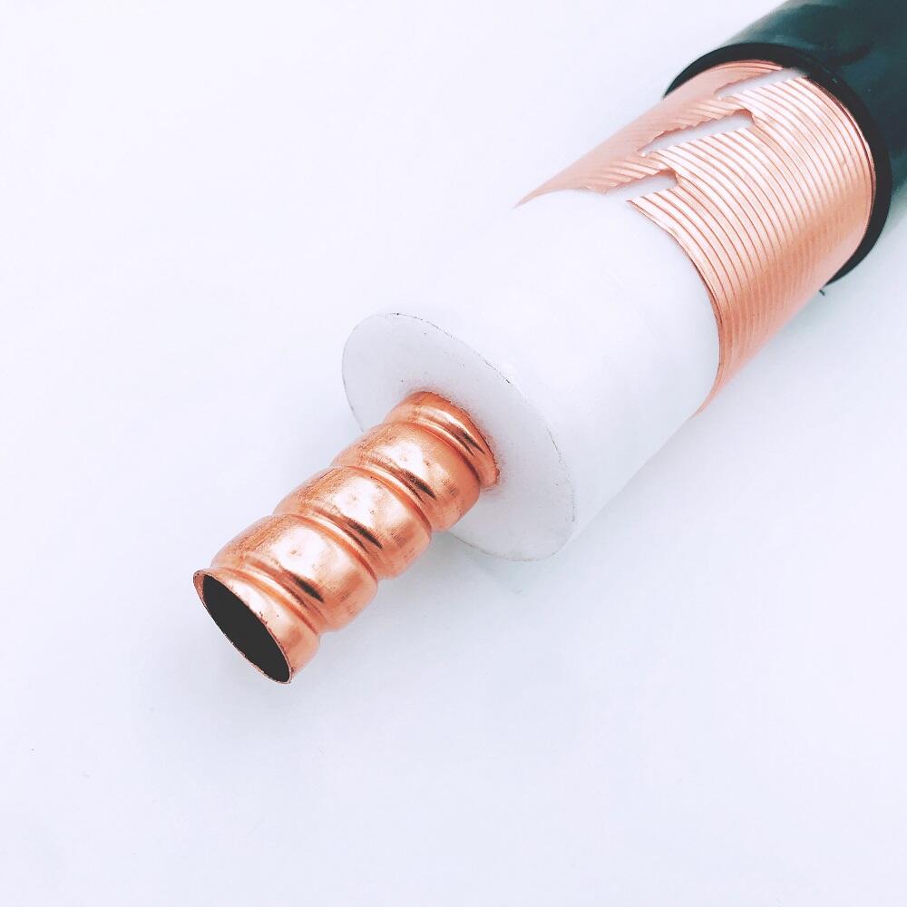
RF feeder cables carry those radio frequency signals back and forth between important parts of cellular networks like antennas and baseband units. Most coaxial designs have four main parts inside them - starting with a copper wire at the center, then wrapped in something called a dielectric material that acts as insulation. Around that goes metal shielding to block out unwanted interference, all protected by an outer jacket against physical damage. The shielding part is pretty critical because it stops electromagnetic noise from messing things up, while the dielectric helps keep everything working smoothly by maintaining proper electrical properties. When we talk about 5G specifically, these low loss cables become absolutely necessary since they need to handle those super high frequency millimeter waves without losing too much signal strength along the way.
Common Coaxial Cable Types: RG vs LMR Series
Telecom operators primarily deploy two types of coaxial feeder cables:
| Series | Attenuation (dB/100ft @ 2GHz) | Use Case |
|---|---|---|
| RG | 6.8–9.1 | Short-distance indoor links |
| LMR | 2.2–3.7 | Low-loss outdoor deployments |
LMR cables offer approximately 23% lower signal loss at high frequencies than standard RG variants, making them better suited for 5G macro sites requiring long cable runs over 100 feet.
Impedance Explained: 50 Ohm vs 75 Ohm in Telecom Applications
When there's an impedance mismatch in the system, signals get reflected back instead of traveling through properly, which messes up how efficiently networks operate. Most people working in broadcast TV still stick with those 75 ohm cables because they work well for that application. But when it comes to cell towers and other wireless infrastructure, almost everyone prefers 50 ohm cables these days. They handle much more power than their 75 ohm counterparts, sometimes as high as 5 kilowatts, while losing less signal strength along the way. According to a recent industry report from early 2024, around 9 out of every 10 telecom companies install 50 ohm cables between antennas and their remote radio units (RRUs). This preference makes sense given the demands of modern cellular networks.
Minimizing Signal Attenuation: Cable Length, Thickness, and Frequency Loss
How Signal Loss Increases with Distance and Frequency
As signals travel further and operate at higher frequencies, they naturally lose strength. The drop off usually falls somewhere between 0.2 to 1.5 dB for every 100 feet of cable, though this varies based on what kind of cable we're talking about and which frequency range it's working in. Take 900 MHz for instance regular old coax cables will see about an 11 dB signal drop after just 100 feet, whereas those fancy new low loss cables bring that down to around 8 dB instead. Things get worse when we move up to higher frequencies. Look at 5G running on 3.5 GHz bands compared to older 4G signals below 2 GHz, the newer tech suffers almost 2.5 times more signal loss. There's actually two different ways these losses behave. When we talk about cable length, the signal gets weaker in direct proportion to how far it travels. But frequency works differently it's not just a little worse, it gets exponentially worse as we go higher. So if someone tries to double their cable run, they'll double their signal loss too. And forget about going much beyond that without some serious signal problems.
Balancing Cable Diameter and Attenuation for Optimal Performance
Larger diameter cables reduce attenuation but increase rigidity and cost. For example, a 0.5-inch cable cuts signal loss by 40% compared to a 0.25-inch version at 3 GHz. However, thicker cables are harder to route in confined spaces. Operators often evaluate trade-offs using the following criteria:
| Diameter (inches) | Flexibility Rating | Attenuation at 3 GHz (dB/100ft) |
|---|---|---|
| 0.25 | High | 6.8 |
| 0.5 | Moderate | 4.1 |
| 0.75 | Low | 2.9 |
Frequency-Dependent Loss Characteristics in 4G and 5G Bands
Today's network infrastructure needs to handle signals across a wide frequency spectrum ranging from 600 MHz all the way up to 40 GHz. Older 4G LTE technology operating between 700 and 2600 MHz generally experiences signal degradation of around 3 to 8 dB for every 100 feet using regular cable installations. Things get trickier when looking at newer technologies. The 5G mid-band at 3.5 GHz faces significantly worse losses, sometimes reaching 12 dB over the same distance. And then there are those high frequency millimeter waves in the 24 to 40 GHz range which absolutely demand special ultra low loss cables just to keep signal strength above dangerous 15 dB drop levels. These differences matter a lot for real world deployment decisions.
Best Practices to Reduce Signal Degradation in Feeder Lines
- Minimize cable runs: Reducing length by 50 feet can cut signal loss by 30–55%, depending on frequency
- Use pre-connectorized cables: Factory-terminated assemblies minimize Passive Intermodulation (PIM) risks during field installation
- Avoid sharp bends: Maintain bend radius at or above 10× the cable diameter to prevent impedance disruptions
- Choose low-loss materials: Foam dielectric cores provide 18–22% better high-frequency performance than solid polyethylene
By aligning cable specifications with deployment distance, frequency, and environmental conditions, operators can reduce attenuation-related outages by up to 67% while preserving SNR (Signal-to-Noise Ratio) above operational thresholds.
Ensuring Frequency and Bandwidth Compatibility for Modern Networks
Supporting 4G LTE and 5G NR: Frequency Range Requirements
Today's communication networks need feeder cables that can handle both 4G LTE frequency ranges from 700 to 2600 MHz as well as the newer 5G NR signals going all the way up to 7.125 GHz. Looking at different parts of the spectrum, the Sub-6 GHz range remains really important for getting that sweet spot between good coverage area and sufficient data capacity. Then there are those millimeter wave frequencies between 24 and 47 GHz which require special cables with almost no signal loss because they work best over shorter distances but offer massive bandwidth potential. For network operators trying to keep up with changing demands, having cables that support multiple frequency bands makes sense since it allows them to get the most out of available spectrum resources as infrastructure continues to evolve over time.
Bandwidth Demands of High-Data-Rate Telecommunications
5G channels require bandwidths of 100–400 MHz per carrier, far exceeding LTE’s 20 MHz limit. To maintain signal fidelity, feeder cables should sustain VSWR ratios below 1.5:1, minimizing reflections that could disrupt 4K video streaming and massive IoT data flows.
Balancing Legacy Network Support with Future-Proof Performance
Operators must maintain compatibility with existing 3G and 4G services while preparing for 5G-Advanced, which targets peak throughputs up to 10 Gbps. Phase-stable cables with consistent dielectric properties ensure reliable performance across mixed-frequency environments, reducing phase distortion in MIMO and beamforming applications.
Evaluating Multi-Band Feeder Cables for Network Flexibility
Dual-band and tri-band feeder cables can reduce infrastructure costs by up to 30% in transitional zones between rural and urban areas. Optimal designs support concurrent transmission at 600 MHz (LTE) and 3.5 GHz (5G), with attenuation no greater than 0.3 dB/m at 40°C, ensuring efficient operation under real-world thermal loads.
Maintaining Signal Integrity: PIM Performance and Installation Factors
Understanding Passive Intermodulation (PIM) in Cellular Systems
Passive Intermodulation, or PIM for short, happens when those non-linear points in passive components start creating these annoying harmonic signals nobody wants. We see this problem getting really bad in 5G networks lately. The jump to higher frequencies around 3.5 GHz actually makes things worse too, causing about 15 to 20 percent more distortion than what we saw with old 4G technology. Field engineers run into several usual suspects when troubleshooting PIM issues. Corroded connectors are a big one, along with those loose fittings that nobody bothered to tighten properly after installation. And let's not forget about cable assemblies that just don't match well together. All these little problems create interference that eats away at network performance and reduces overall capacity over time.
How PIM Affects Network Capacity and Call Quality
Research conducted in field settings throughout 2023 indicates that when passive intermodulation (PIM) interference occurs, it can slash network throughput by as much as 40 percent at busy urban cell towers during rush hours. When multiple carriers operate in tight spaces, these problems become even worse, leading to dropped calls and frustratingly slow internet connections for users. Network operators who work with feeder cables where PIM measurements go above -140 dBc tend to see around 30% increase in customer service tickets complaining about poor audio quality on phone calls and unstable connections. This isn't just an abstract problem for engineers either it directly affects end user experiences across densely populated areas.
Selecting and Installing Low-PIM Feeder Cables for Dense Environments
Low-PIM feeder cables featuring silver-plated connectors reduce intermodulation by 85% compared to standard aluminum interfaces. Critical installation practices include:
- Torque-controlled tightening (25–30 N·m for N-type connectors)
- Avoiding bends tighter than 10× the cable diameter
- Applying anti-oxidation gel on outdoor terminations
In millimeter-wave 5G deployments, cables rated at PIM ≤ -155 dBc improve signal-to-noise ratios by 12 dB, extending effective coverage radius by 18%. Regular PIM testing every 6–12 months helps maintain compliance with 3GPP TS 37.145 standards for interference control.
Environmental Durability and Long-Term Feeder Cable Reliability
Outdoor Installation Challenges: UV, Moisture, and Temperature Extremes
Feeder cables installed outdoors have to deal with all sorts of tough conditions. Prolonged exposure to UV light is a big problem, often causing polyethylene jackets to break down about 40 percent over just five years. Then there's the extreme temperature swings from -40 degrees Celsius up to 85 degrees Celsius, plus torrential rains sometimes exceeding 100 millimeters per hour that can really mess with poor seals on the cables. When these are put along coastlines, things get even worse because salt fog causes corrosion issues. Connectors start failing faster and signals drop off significantly if they aren't properly protected against this marine environment.
Key Protection Features: UV Resistance, Water Blocking, and Thermal Stability
To withstand harsh conditions, modern feeder cables incorporate:
- UV-stabilized jacketing (tested per UL 1581 MW 1100) retaining ≥90% tensile strength after 3,000 hours of exposure
- Triple-layer water protection combining dry-core technology with welded aluminum armor to prevent moisture ingress
- Thermally stable dielectrics maintaining VSWR <1.3:1 across temperatures from -55°C to +125°C
These features ensure consistent electrical performance despite fluctuating environmental conditions.
Industry Standards for Durable, Outdoor-Rated Feeder Cables
Compliance with Telcordia GR-13-CORE guarantees a minimum 20-year service life in demanding outdoor environments. Essential certifications include:
| Standard | Key Requirement | Relevance to Cables |
|---|---|---|
| IEC 60754-1 | Halogen-free smoke emission | Safe tunnel/basement installations |
| EN 50288-7-1 | UV/weathering resistance | Direct sunlight exposure |
| ETSI EN 302 066 | IP68 submergence protection | Flood-prone cell sites |
RF Feeder Cables FAQ
What are RF feeder cables used for?
RF feeder cables are used to carry radio frequency signals between key components like antennas and baseband units in cellular networks.
Which types of coaxial cables are commonly used in telecom?
Telecom operators primarily use RG and LMR coaxial cables, with LMR offering lower signal loss at higher frequencies.
Why do telecom companies prefer 50 Ohm cables?
50 Ohm cables are preferred because they handle more power efficiently with less signal loss compared to 75 Ohm cables.
How does cable diameter affect signal attenuation?
Larger diameter cables reduce signal attenuation but increase rigidity and cost, requiring careful evaluation of trade-offs.
How can signal degradation in feeder lines be minimized?
Signal degradation can be minimized by reducing cable length, using pre-connectorized cables, avoiding sharp bends, and choosing low-loss materials.
What environmental challenges do outdoor feeder cables face?
Outdoor feeder cables face challenges like UV exposure, moisture, temperature extremes, and corrosion in marine environments.
Table of Contents
- Understanding RF Feeder Cables: Core Functions and Types
- Minimizing Signal Attenuation: Cable Length, Thickness, and Frequency Loss
- Ensuring Frequency and Bandwidth Compatibility for Modern Networks
- Maintaining Signal Integrity: PIM Performance and Installation Factors
- Environmental Durability and Long-Term Feeder Cable Reliability
-
RF Feeder Cables FAQ
- What are RF feeder cables used for?
- Which types of coaxial cables are commonly used in telecom?
- Why do telecom companies prefer 50 Ohm cables?
- How does cable diameter affect signal attenuation?
- How can signal degradation in feeder lines be minimized?
- What environmental challenges do outdoor feeder cables face?