EN
EN

4.3-10 to 7/16 DIN Cable Assembly Selection Guide
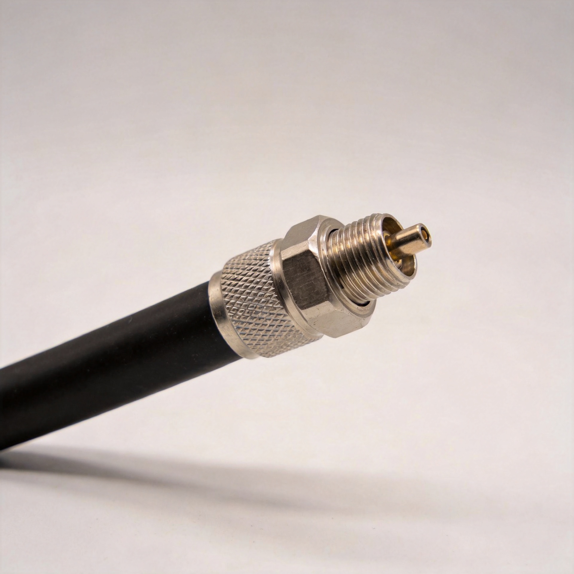
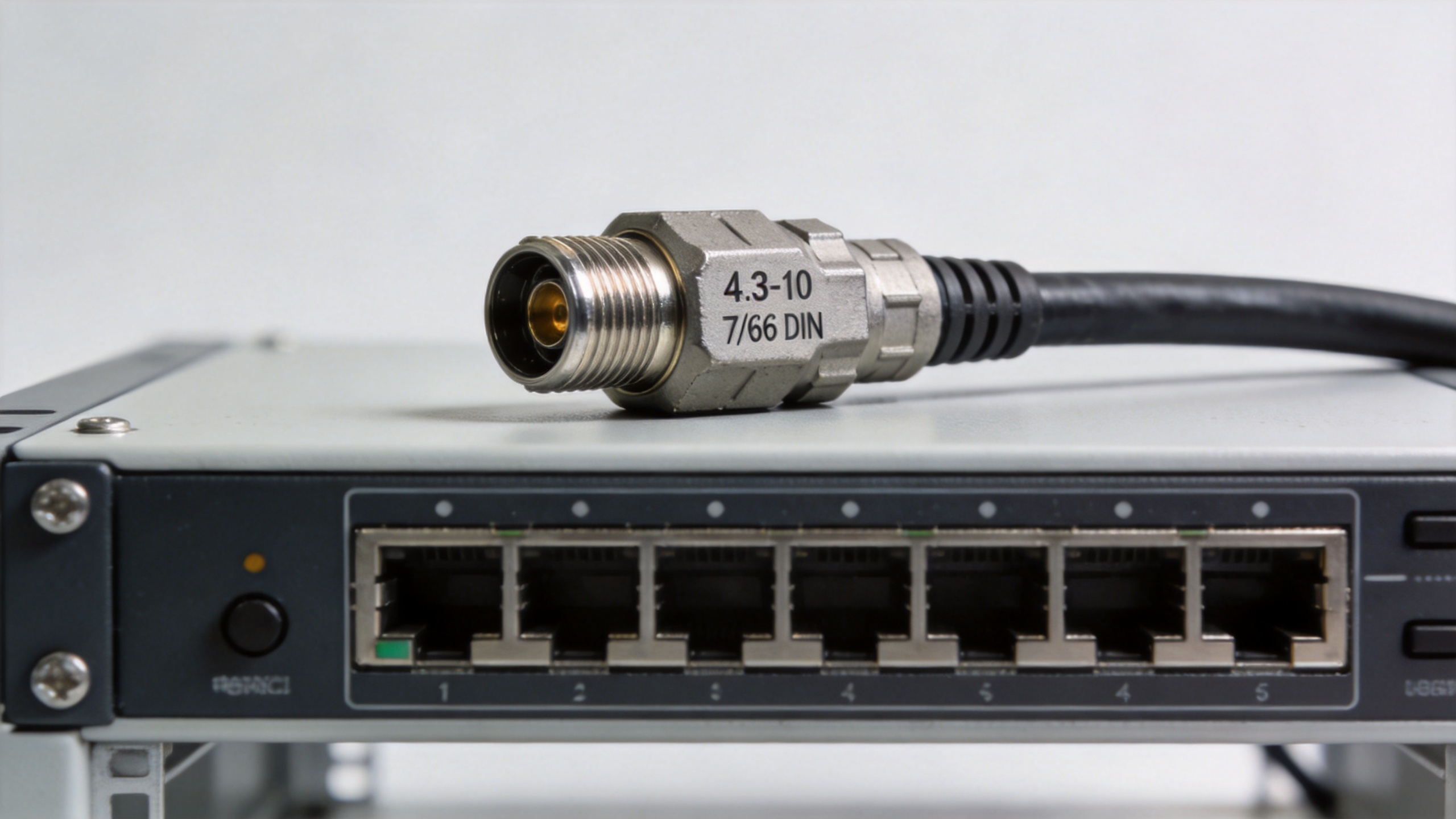
When a telecom upgrade connects equipment using a compact 4.3-10 interface to a legacy or higher-power 7/16 DIN port, the cable between them is not a minor adapter. It is part of the RF path. Selecting coax cable assemblies for this transition means confirming electrical compatibility, connector gender, cable construction, installation constraints, and the acceptance checks that will protect the link after deployment.
From a telecom procurement perspective, the most useful question is not “Which connector is better?” Both interfaces can be appropriate. The question is whether the complete assembly fits the port pair, frequency band, loss budget, mechanical environment, and service model of the installation.
Start With the Two RF Interfaces, Not the Cable Length
A 4.3-10 to 7/16 DIN assembly joins two different connector families, so begin with the equipment interfaces at both ends. Confirm the required plug or jack configuration from the equipment drawing, not from a shorthand description in a purchase list. A 4.3-10 interface is commonly specified as a 50-ohm RF connector under IEC 61169-54; 7/16 DIN references include IEC 61169-4. Those standards help identify the interface, but they do not automatically approve a specific finished assembly for your system.
Check the following before specifying coax cable assemblies:
- connector family and mating gender at each equipment port;
- nominal system impedance, typically 50 ohms in this type of RF chain;
- operating frequency range and the frequency at which performance must be verified;
- straight, right-angle, or panel-access requirements;
- low-PIM, return-loss, or VSWR limits stated by the project; and
- the approved torque and weatherproofing procedure for the field team.
You might assume insertion loss is the single number to optimize—and it is important. Actually, return loss and PIM requirements can be just as consequential when multiple antenna paths, high transmit power, or sensitive receive channels share the same installation.
Match Cable Construction to the Installation Path
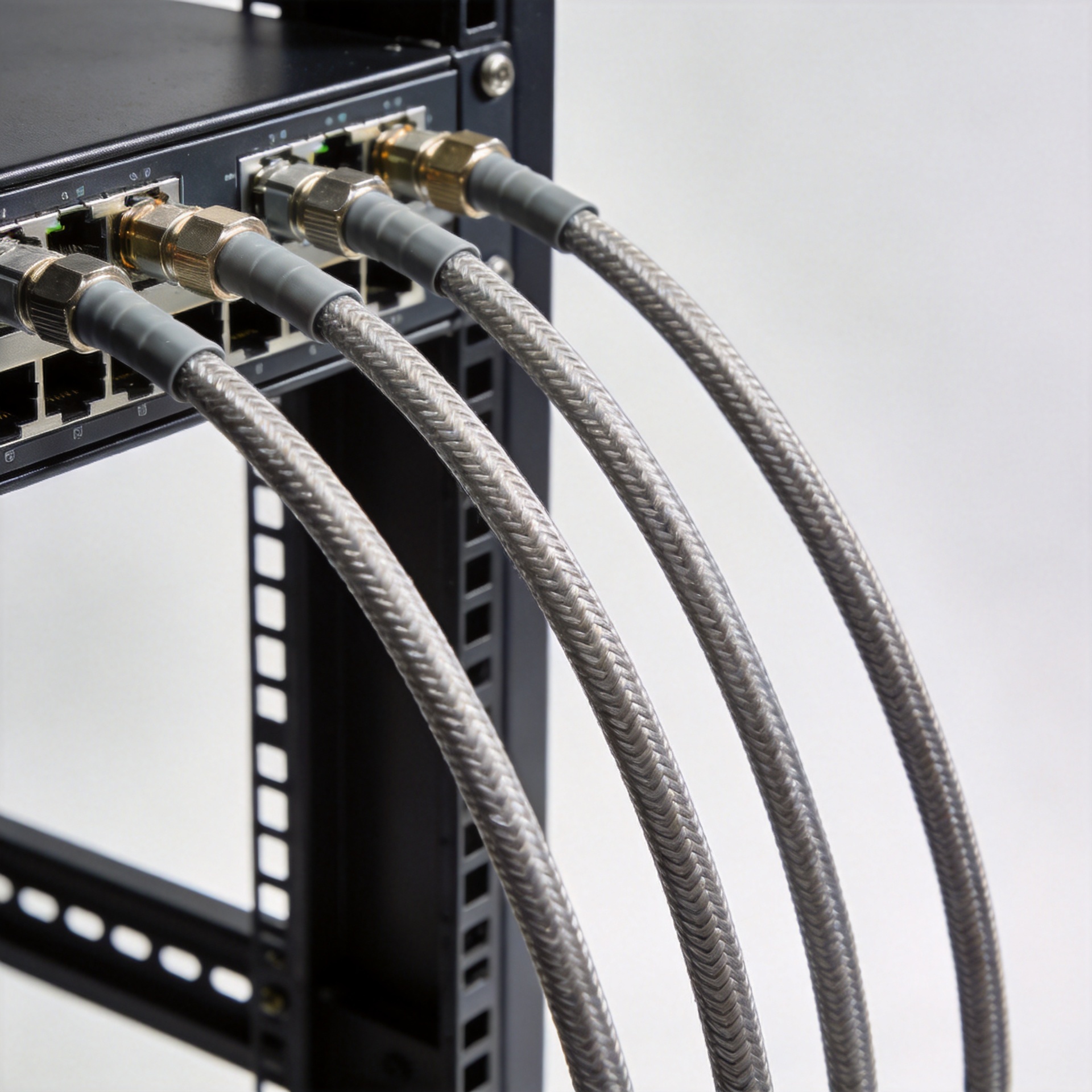
The connector pair defines the endpoints; the cable determines how the assembly behaves between them. Flexible, super-flexible, corrugated, semi-rigid, and hand-formable constructions are used for different routing conditions. For a short equipment jumper with repeated bends, flexibility and minimum bend radius may matter more than for a fixed, straight run. For an outdoor feeder transition, attenuation, shielding, crush resistance, and environmental protection may take priority.
Published low-PIM 4.3-10 to 7/16 DIN products commonly use 50-ohm cable constructions, but that is only a starting point. Ask the supplier to confirm the finished assembly’s cable type, overall length, connector orientation, and applicable electrical values at your operating band. Do not transfer a value from one cable family to another simply because the connectors look the same.
| Selection factor | What to confirm | Why it matters |
|---|---|---|
| Electrical path | 50-ohm system match, frequency range, VSWR/return loss and PIM requirement | Supports signal integrity and avoids accepting an assembly on connector names alone. |
| Mechanical path | Length, bend radius, connector angle, cable diameter and strain relief | Prevents routing choices from loading the connector interface. |
| Installation environment | Indoor/outdoor exposure, sealing method, vibration and access clearance | Determines whether a technically correct assembly remains reliable in service. |
| Supply control | Drawing revision, labeling, inspection records and replacement consistency | Helps standardize spares across repeated sites. |
Specify a Custom Cable Assembly With a Complete Requirement Set
A custom cable assembly should be released against a clear requirement set rather than a connector-only description. Include both end interfaces, gender, cable family, finished length and tolerance, routing orientation, electrical acceptance criteria, environmental needs, marking, packaging, and quantity. If the application has a low-PIM requirement, say so explicitly and identify the test condition requested by the project.
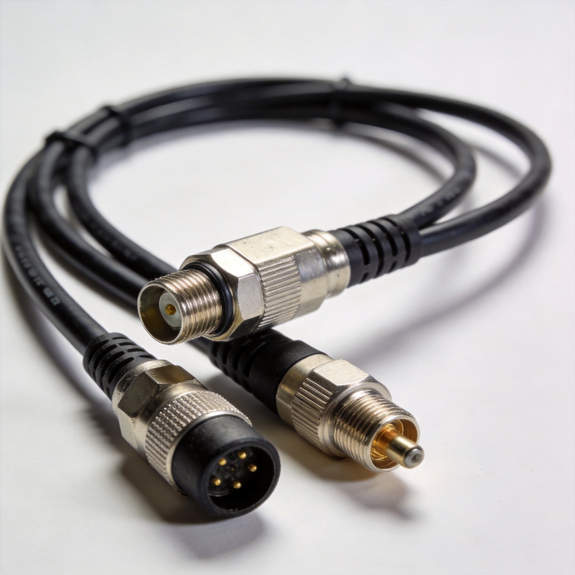
For example, a confirmed product option is the 1/2" Super Flexible Jumper Cable 4.3-10 Male To 7/16 DIN Male Cable Assembly. Treat the product title as an interface and cable-format reference; verify all project-specific electrical and mechanical requirements with the supplier before approval.
So that is the electrical side of the decision. Now—and this is where many purchase specifications fall short—the mechanical interface. A cable can meet a bench requirement yet be a poor field choice if its bend radius, connector clearance, or strain-relief plan conflicts with the actual cabinet or tower route.
Use a Practical Procurement Checklist
- Map the ports: obtain the latest equipment interface drawings and confirm 4.3-10 and 7/16 DIN genders.
- Set the RF acceptance criteria: state impedance, operating band, VSWR/return loss, insertion-loss, and PIM requirements where applicable.
- Select the cable format: compare flexibility, diameter, attenuation, shielding, and bend radius against the route.
- Define the environment: identify outdoor exposure, sealing responsibility, vibration, and temperature conditions.
- Control the build: approve a drawing, label convention, inspection requirement, and sample process for repeat orders.
- Plan serviceability: standardize lengths and orientations where possible so field spares stay interchangeable.
Optimizing one jumper for one site is different from standardizing coax cable assemblies across many sites. At fleet scale, consistent connector orientation, cable labeling, and approved replacement configurations can reduce training and spare-part confusion.
RF Cable Assembly Review Questions for Each Release
Use the following review questions when comparing coax cable assemblies from multiple sources. First, does each proposed coax cable assembly show the exact 4.3-10 and 7/16 DIN genders on its drawing? Second, does the coax cable assembly state the cable type, finished length, and bend-radius requirement? Third, does the coax cable assembly include the electrical acceptance conditions required for the band and installation?
For repeat deployments, put the same questions on every custom cable assembly purchase line. A custom cable assembly drawing should identify connector orientation, cable construction, labeling, and test requirements. The approved custom cable assembly sample should also be traceable to the drawing revision. This approach gives purchasing, engineering, and field teams one common reference rather than separate assumptions about the same RF path.
Questions for the supplier
- Can the supplier confirm the requested electrical results for these coax cable assemblies at the specified frequency range?
- What cable construction and connector termination process is used for this custom cable assembly?
- Are drawings and labels available to distinguish otherwise similar coax cable assemblies in a spares inventory?
- Can the same custom cable assembly configuration be repeated when future site orders are released?
The goal is not to add paperwork for its own sake. It is to ensure that coax cable assemblies are selected as controlled RF assemblies, with the interface, cable, and verification requirements tied together. When a project needs a custom cable assembly, the complete requirement set makes comparison more meaningful and helps avoid late changes during installation.
Make the Final Choice at Assembly Level
A suitable 4.3-10 to 7/16 DIN solution matches the entire RF system, not just the connector pair. Switching connector series may solve an immediate interface constraint but can create a cable-routing or spare-parts problem if the surrounding assembly is not reviewed at the same time. Use the equipment drawings, site conditions, and test requirements to turn the selection into an approved configuration.
For buyers sourcing RF interconnects, Zhenjiang Jiewei supports cable assemblies alongside RF connectors, feeder cables, and related communication equipment accessories. Share the interface drawings, desired cable format, length, quantity, and acceptance criteria to evaluate a suitable custom cable assembly configuration.