EN
EN

RF Cable Assemblies: How to Match Connectors, Cable and Frequency
Choosing RF cable assemblies is not a matter of selecting two connector names and a length of coax. A finished assembly is a signal path: its connector interfaces, cable construction, operating band, routing conditions, and termination quality must work together. For telecom equipment builders, antenna-system integrators, test labs, and industrial OEMs, a structured selection process reduces rework before installation and avoids surprises during commissioning.
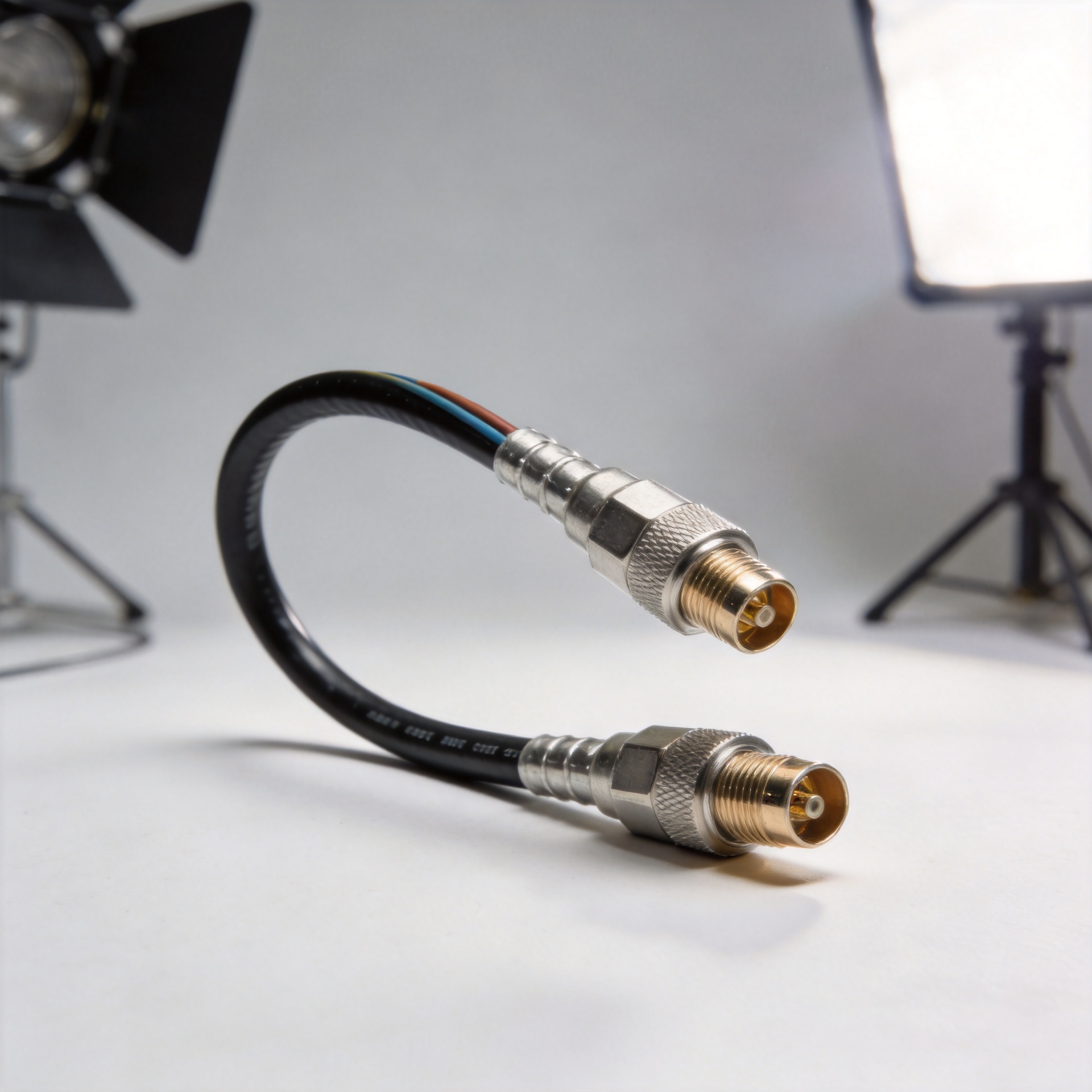
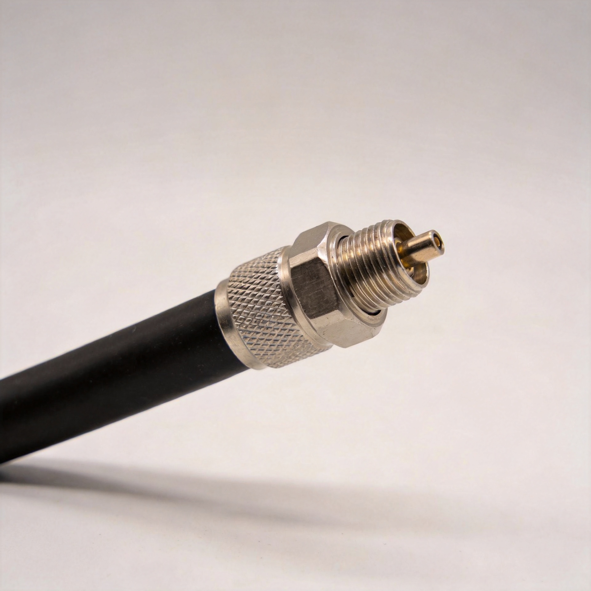
An RF coaxial cable assembly combines coaxial cable with terminated RF connectors to carry a controlled-impedance signal between two points. Start with the equipment interface and operating environment rather than the catalog photo. Work from the system requirement toward the assembly specification.
Start With the Two Mating Interfaces
First, document both ends of the connection. Record the connector series, gender, coupling style, impedance, panel or cable mounting arrangement, and any mechanical constraints around the port. Connector families such as 7/16 DIN, 4.3-10, N-type, SMA, TNC, and BNC serve different size, power, frequency, and installation needs. A correct series name alone is insufficient when the mating side, straight or right-angle body, and interface gender have not been confirmed.
For outdoor telecom work, a compact 4.3-10 interface may suit a space-constrained radio or antenna connection, while a 7/16 DIN configuration can be appropriate where robust, larger-format feeder interfaces are already specified. In equipment cabinets or test setups, smaller interfaces may make routing easier, provided the frequency and power requirements are met. Do not solve a mismatch with an unnecessary adapter unless the added connection point has been reviewed in the RF and mechanical design.
- Check the OEM drawing or interface callout for each end.
- Confirm male/female configuration and whether the port is standard or reverse-polarity.
- Allow space for coupling nuts, torque tools, weatherproofing, and service access.
- Specify connector plating, sealing, and mating-cycle needs when the environment requires them.
Choose the Cable Before You Lock the Length
The cable determines much of the assembly’s electrical loss, shielding, flexibility, diameter, weight, and minimum bend radius. A low-loss feeder is often useful for longer runs where attenuation matters, but its larger diameter and stiffness can make equipment-side routing difficult. A more flexible cable can simplify a short jumper or moving connection, yet it should still be evaluated for loss, shielding, and bend performance at the required frequency.
Use the actual routed path, not the straight-line distance. Include vertical drops, tray transitions, service loops, connector entry direction, and the minimum bend radius stated for the selected cable. Excess cable creates management and loss issues; insufficient length can force sharp bends or tensile stress at the termination. In custom RF cable assemblies, the specified length should state the measurement convention—such as connector end to connector end—so engineering, purchasing, and production interpret it the same way.
Match Frequency Capability to the Whole Signal Path
Frequency is an assembly-level requirement. The connector, cable, adapters, and termination process must all support the intended band. Ask for the required frequency range first, then compare it with the applicable component ratings and test conditions. As frequency rises, small discontinuities at a connector interface, a poor termination, or a tight bend can have a larger effect on return loss and insertion loss.
For broadband or multi-band systems, specify the complete operating range rather than only the nominal center frequency. If the assembly supports sensitive receive paths, densely packed RF equipment, or co-located transmit/receive antennas, shielding effectiveness and connector consistency deserve explicit review. For high-power applications, also verify cable and connector suitability under the intended duty cycle rather than assuming that a mechanically similar assembly will behave identically.
Use Installation Conditions as a Selection Filter
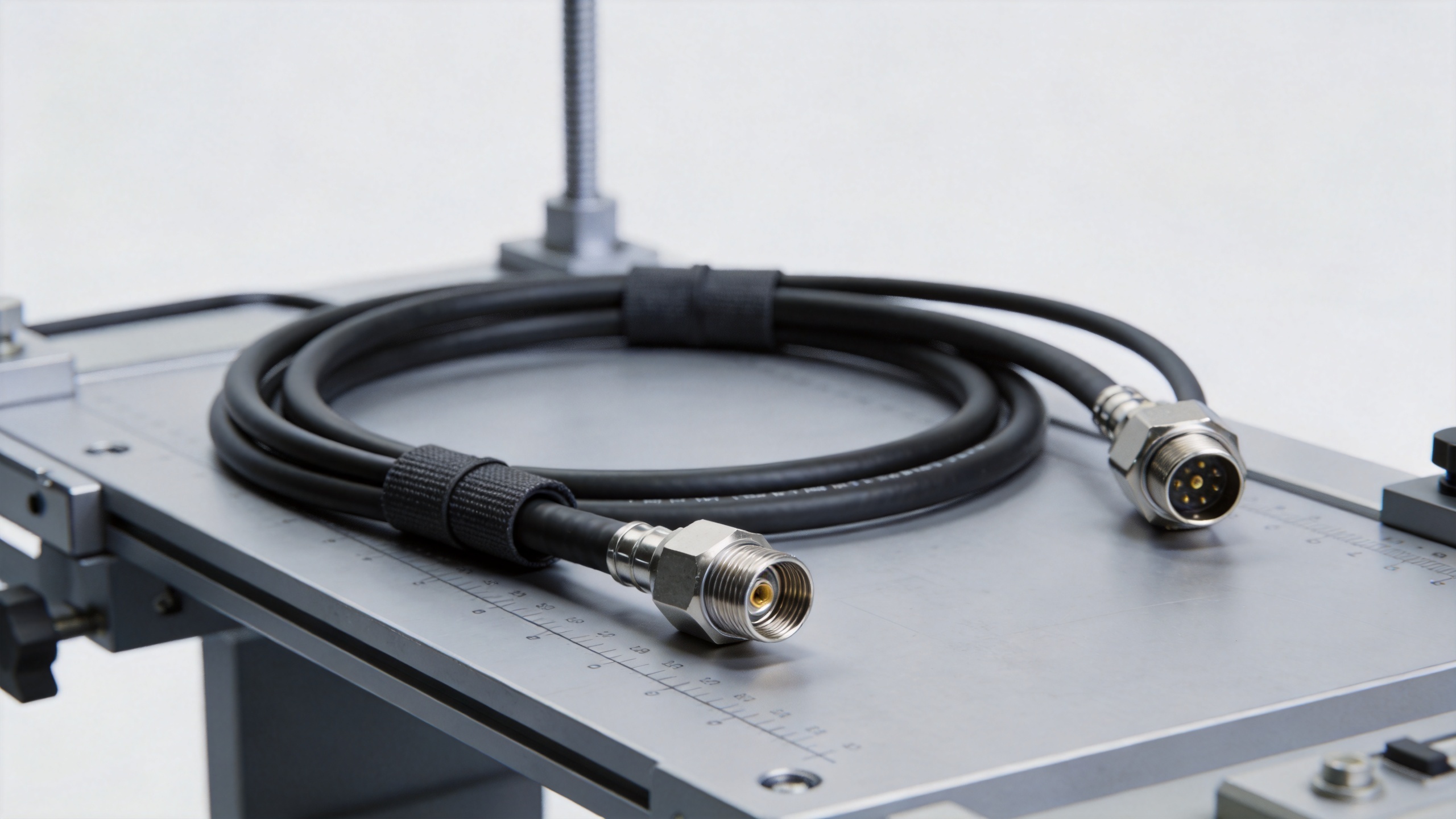
Many RF failures begin as mechanical or environmental oversights. Indoor cabinet jumpers, rooftop feeders, tower runs, mobile broadcast links, and industrial enclosures present different risks. Review temperature exposure, UV, moisture, salt spray, vibration, cable support spacing, pulling force, and repeated flexing. Protect the connector-to-cable junction with suitable strain relief and ensure that routing does not violate the cable’s bend-radius requirement.
For example, a mixed-interface assembly may be needed when one side uses a compact radio interface and the other connects to an existing feeder system. A real configuration to review is this 1/2" Super Flexible Jumper Cable 4.3-10 Male to 7/16 DIN Male Cable Assembly. Its suitability still depends on the project’s confirmed frequency, cable-routing, and environmental requirements; the product title should not replace a full technical review.
Questions to Ask Before Ordering RF Cable Assemblies
Before approving RF cable assemblies, ask the supplier to restate the two connector interfaces, the intended cable family, finished length, and required frequency range. This simple confirmation catches many ordering errors. For a custom RF coaxial cable assembly, the drawing should also show connector orientation, the measurement points used for length, and any boot or strain-relief requirement.
Ask which electrical results will be checked for the RF cable assemblies and under what test conditions. The answer should distinguish an interface check from an assembly-level result. When repeatability matters, request a consistent build process and a report format that engineering can compare with the RFQ. For a replacement RF coaxial cable assembly, compare the installed route and connector access, not only the printed part number.
It also helps to separate mandatory requirements from preferences. Frequency range, impedance, mating interface, maximum loss, environmental exposure, and bend radius are typically mandatory. Color, labeling, packing format, and service-loop preference can be secondary. This makes quotations for RF cable assemblies easier to compare and helps avoid a lower-cost option that omits an electrical or mechanical requirement.
Finally, plan acceptance before the order ships. Inspect connector protection, labeling, and physical routing condition on arrival, then review the agreed electrical evidence for the RF coaxial cable assembly. If the system is sensitive to return loss, phase, or loss variation, define that acceptance criterion in the RFQ rather than introducing it after delivery.
Turn the Requirement Into a Procurement-Ready Specification
A good RFQ for RF cable assemblies makes quality verification practical. Include both connector callouts, cable type or required electrical characteristics, finished length and tolerance, frequency range, impedance, installation environment, labeling, packaging, and required documentation. If phase matching, low PIM, specific return-loss limits, or special jackets are required, state them clearly rather than treating them as implied.
Before release, request a drawing or build specification that identifies the connector combination and cable routing assumptions. For custom cable assemblies, pre-shipment RF sweep testing can provide useful confirmation of insertion-loss and return-loss performance under stated conditions. That does not eliminate incoming inspection, but it gives procurement and engineering a common acceptance basis.
A Practical Final Checklist
- Confirm both mating interfaces, gender, impedance, and available installation clearance.
- Define the full operating frequency range and any return-loss, VSWR, loss, shielding, or power requirements.
- Select a cable construction that balances attenuation, flexibility, diameter, and bend radius for the actual route.
- Specify finished length, measurement points, connector orientation, and strain-relief needs.
- Check environmental exposure and required protection for outdoor, mobile, or industrial installation.
- Request drawings, traceability or labeling as needed, and relevant electrical test documentation.
Make the Three Choices Together
The most reliable RF cable assemblies result from matching the connector, cable, and frequency requirement as one design decision. Start at the mating interfaces, model the real cable route, confirm the electrical band and loss budget, then turn the result into a clear build specification. This approach gives integrators and procurement teams a better basis for comparing options, approving custom assemblies, and protecting system performance after installation.