EN
EN

Low-Loss RF Feeder Cable: A Buyer’s Technical Checklist
Buying a microwave cable for an RF feed path is not a matter of choosing the lowest dB figure on a catalog page. Procurement, RF engineering, and installation teams need the same answer to a more practical question: will this cable deliver the required loss, fit the route, survive the environment, and arrive with evidence that it matches the approved specification?
For feeder and coaxial cable purchases, start with the system rather than the spool. A microwave cable is part of a chain that includes connectors, weatherproofing, routing hardware, and test practice. This checklist helps buyers turn those dependencies into an RFQ and an incoming-inspection plan.
1. Define the RF operating window before comparing cable loss
Ask for attenuation at your actual operating frequency range, not just at a convenient low-frequency reference point. Coaxial attenuation changes with frequency and length, so a loss-per-100-metre value is meaningful only when its frequency, temperature condition, and unit are clear. Calculate the expected cable contribution for the longest installed run, then leave margin for connectors, jumpers, splitters, and normal installation variation.
Also confirm impedance, frequency range, power requirement, and the return-loss or VSWR requirement for the entire assembly. Low insertion loss is important, but it is not the whole story. A poorly matched termination can undermine a carefully calculated loss budget through reflections.
- State the lowest and highest operating frequencies.
- State the maximum route length and allowable end-to-end loss.
- Specify the measurement frequency points and test method in the RFQ.
- Ask whether supplied figures apply to bare cable or a terminated assembly.
2. Select cable size as a loss-versus-installation trade-off
Larger-diameter coax generally reduces attenuation, but adds weight, stiffness, and minimum bend radius. That trade-off changes from site to site. A main feeder on a tower may justify a larger microwave cable; a short equipment-room jumper may value manageable routing and connector geometry more highly.
Do not accept a diameter choice in isolation. Review pulling path, tray width, clamp spacing, entry points, wind loading, and whether the installation must make a turn near an antenna, cabinet, or bulkhead. The minimum bend radius should be treated as a design rule, not an afterthought. A cable that is forced around too tight a bend may look intact while its electrical performance has changed.
| Buyer question | Why it matters | Evidence to request |
|---|---|---|
| What attenuation applies at our band? | Supports a credible link-budget calculation. | Frequency-specific attenuation table. |
| What is the minimum bend radius? | Prevents installation damage and hidden dielectric stress. | Installation drawing or datasheet. |
| What is the cable weight per metre? | Influences tower loading, supports, and handling. | Construction and mechanical data. |
| What connector options are qualified? | Prevents an otherwise suitable cable from becoming an interface problem. | Assembly configuration and test scope. |
3. Verify conductor, dielectric, shield, and jacket for the deployment
The construction details determine whether a feeder remains predictable after installation. Ask how the center conductor, dielectric, outer conductor, and jacket are specified—not merely whether the product is described as “low loss.” The dielectric and conductor geometry influence attenuation and impedance stability. The outer conductor and shield continuity influence mechanical robustness and RF containment. The jacket determines whether the cable is suitable for UV exposure, moisture, abrasion, flame-related project requirements, or indoor routing rules.
For outdoor work, an ingress rating alone is not a complete environmental answer. UV exposure, temperature cycling, vibration, and site atmosphere can all affect long-term performance. For indoor or transit applications, clarify applicable flame, smoke, and halogen requirements with the project authority instead of assuming a jacket description automatically satisfies every local rule.
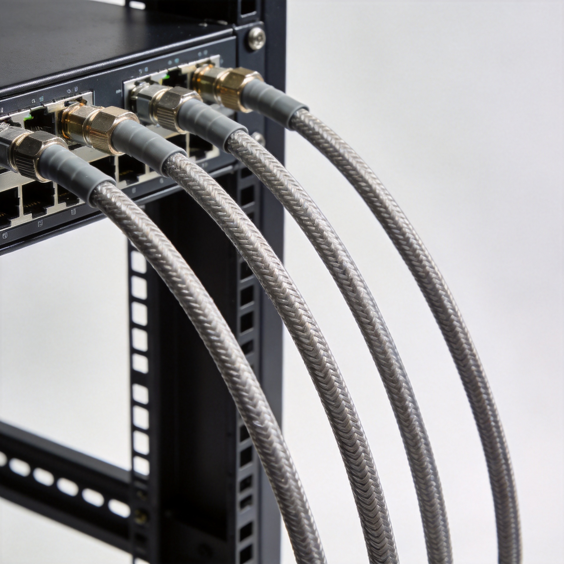
Buyers evaluating flexible or semi rigid RF cables should be especially explicit about routing and service conditions. Flexibility can simplify installation, but the product still needs to meet the required loss and mechanical limits at the intended frequency.
4. Treat connectors and termination as part of the cable specification
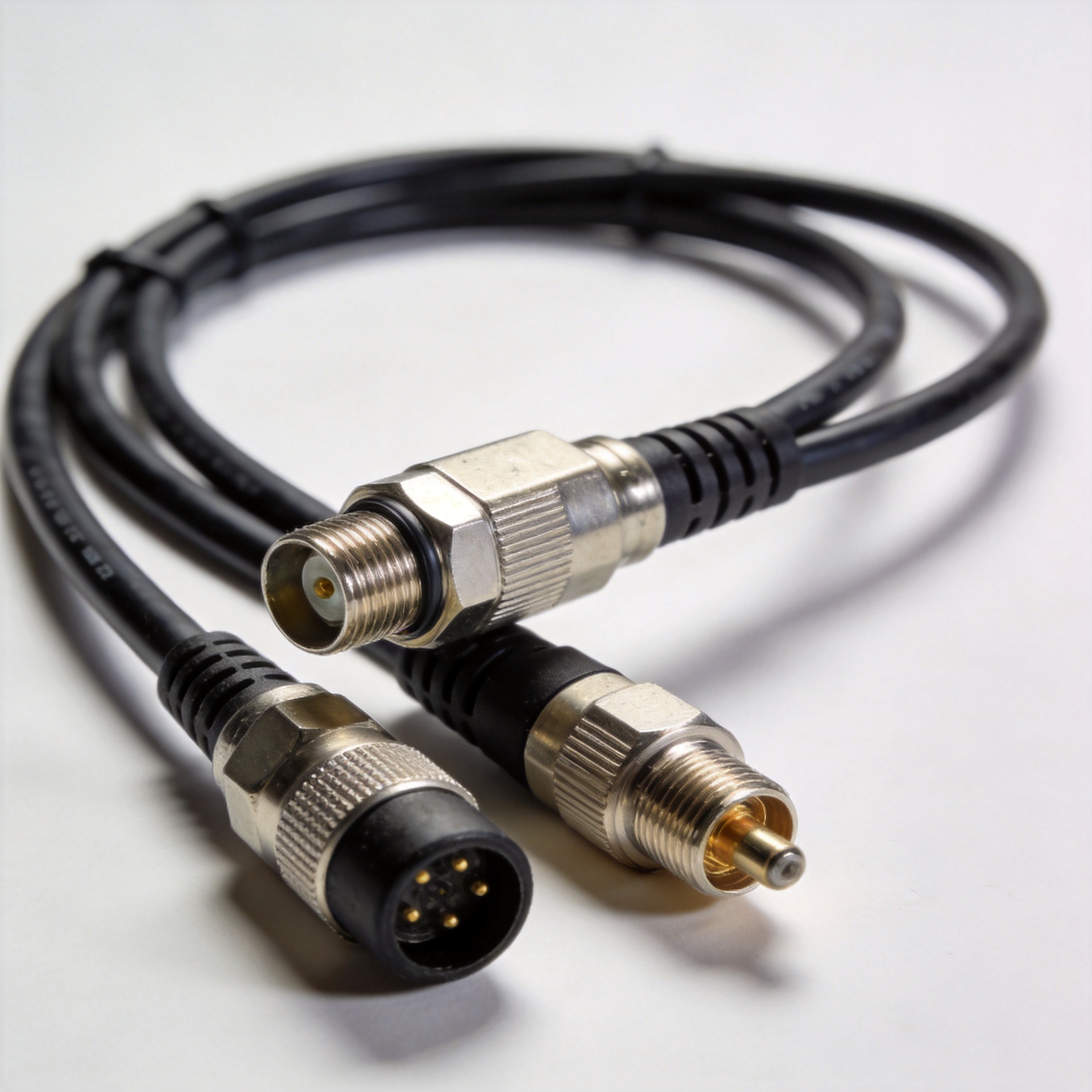
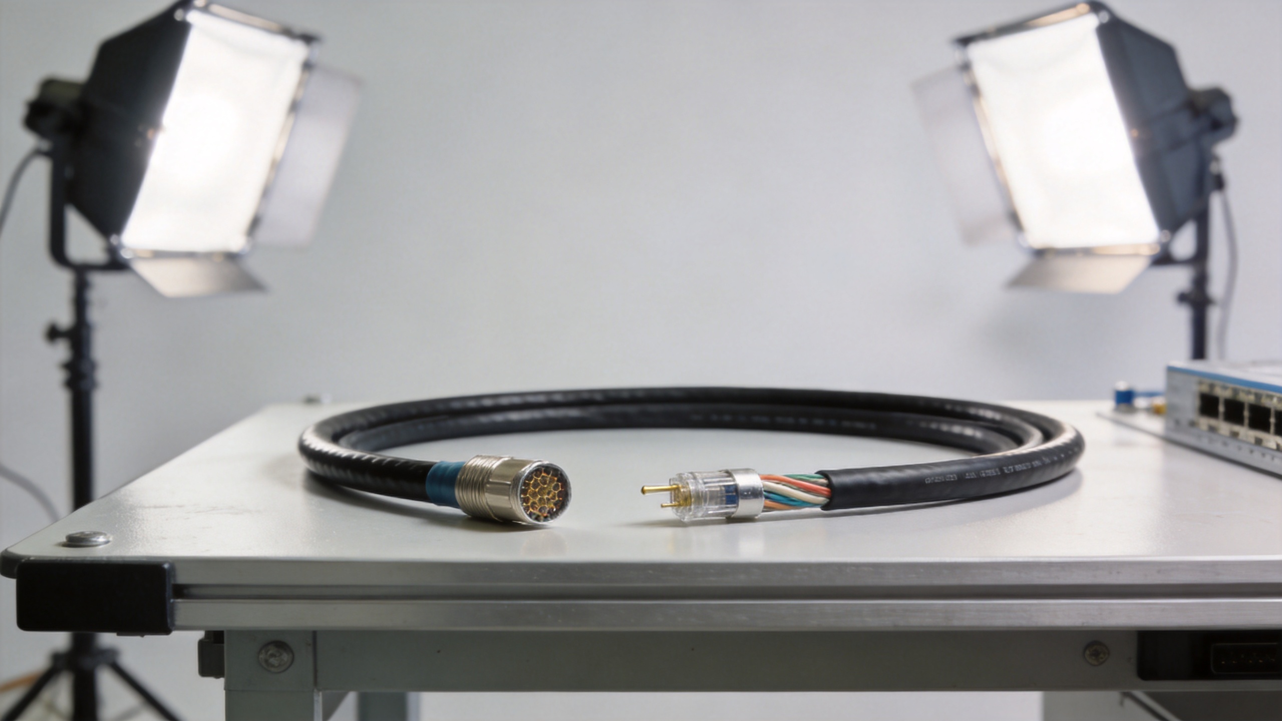
A microwave cable assembly is only as strong as its interfaces. Specify connector series, gender, mating interface, torque requirement, and any right-angle or bulkhead constraints. Then require the supplier to state whether the electrical test applies to the finished assembly, not just the cable stock.
A useful rule for procurement teams is to separate design qualification from batch acceptance. A qualified sample shows that a configuration can work; it does not prove that every delivered assembly matches it. For critical RF paths, request batch identification, relevant test records, and a clear plan for incoming VSWR or insertion-loss verification. This is particularly important when routes are long, sites are difficult to access, or rework after commissioning would be expensive.
5. Put installation controls in the purchase specification
Many feeder issues begin after the product has passed factory inspection. Include installation controls in the project package: bend-radius limits, pulling guidance, support spacing, connector cleaning, torque verification, and weatherproofing procedure. If a site has tight routing, tell the supplier early so the connector orientation and assembly length can be reviewed before production.
For projects needing a 1/2-inch flexible cable format, buyers can review the verified product page for HCAAY(Z)-50-12, 1/2-inch Low Loss Flexible Cable with Flame Retardant Halogen Free Jacket alongside their own required loss, jacket, connector, and test criteria. The product page is a starting point for configuration review—not a substitute for a project-specific RFQ.
6. Use this final supplier and receiving checklist
- Confirm the exact frequency range, impedance, maximum run length, and link-budget allowance.
- Compare attenuation at the actual operating band using the same units and stated conditions.
- Check cable diameter, weight, bend radius, and route constraints together.
- Confirm conductor, dielectric, shield, and jacket requirements for the real environment.
- Lock connector interfaces, orientation, torque, and assembly length before release.
- Request test scope for the finished assembly, plus batch identification where needed.
- Define receiving inspection and pre-commissioning sweep checks before shipment arrives.
- Ask for applicable standards, material declarations, and documentation required by the destination project.
Make the decision easy to audit
The right microwave cable is the one that meets a documented electrical budget while remaining installable, maintainable, and verifiable in its actual environment. If your priority is minimum signal loss on a long run, diameter and frequency-specific attenuation deserve more weight. If the route is constrained or service access is frequent, bend radius, connector geometry, and assembly repeatability may matter just as much.
Turn this checklist into an RFQ matrix, require evidence against each line item, and verify the delivered assembly before it becomes part of a live RF path. That approach gives purchasing teams a defensible comparison and gives engineers fewer surprises at commissioning.
RFQ wording that prevents ambiguous cable comparisons
Use a short, repeatable request format when asking suppliers to quote a microwave cable. Name the operating band, route length, impedance, connector pair, and required electrical evidence. This makes every microwave cable quote comparable and prevents a microwave cable substitution from slipping through on a general description alone.
Technical questions to put on every line item
- For this microwave cable, what attenuation applies at each specified frequency?
- For this microwave cable, what finished-assembly VSWR or return-loss evidence can be supplied?
- For this microwave cable, what minimum bend radius applies during installation and in service?
- For this microwave cable, what jacket construction suits the project environment?
- For this microwave cable, what connector torque and cleaning instructions apply?
- For this microwave cable, how is batch identity linked to test records?
- For this microwave cable, is the quoted result for cable bulk stock or the completed assembly?
- For this microwave cable, which applicable standards or material declarations can be reviewed?
The same discipline applies when comparing semi rigid RF cables. A semi rigid RF cables option may be appropriate where routing geometry, frequency stability, and mechanical protection fit the application, while a flexible microwave cable may be more practical for field installation. Do not treat semi rigid RF cables as an automatic upgrade: assess the bend requirement, connector design, assembly process, and service access. For a production order, specify whether semi rigid RF cables require phase, amplitude, or batch-consistency controls.
Before approving a microwave cable delivery, compare the received label, length, interface, and test documents against the RFQ. Before pulling a microwave cable into place, inspect the route and supports. Before commissioning a microwave cable run, confirm the connector torque and complete the planned electrical sweep. These checks give both engineering and purchasing a traceable record of what was selected and installed.