
Understanding the Role of Feeder Cable in Base Station Signal Integrity
The Function of Feeder Cable in RF Signal Transmission
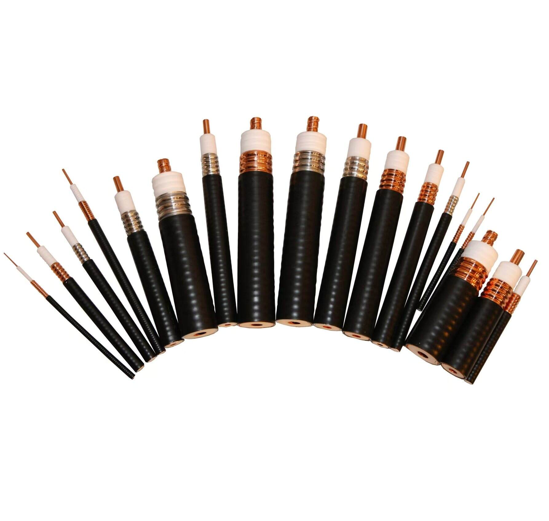
Feeder cables act as the main link carrying radio frequency (RF) signals from the Remote Radio Unit (RRU) to antennas within base station setups. Made with shielding layers and special insulation materials, these coaxial cables help reduce signal loss and block unwanted electromagnetic interference (EMI). The ability to keep signals strong across distances ensures dependable operation for both LTE and emerging 5G networks. Network designers actually highlight this reliability aspect quite often when talking about proper cellular infrastructure setup according to industry standards documents.
Key Challenges Affecting Signal Stability in Feeder Cable Systems
Signal stability hinges on overcoming three primary challenges:
- Interference susceptibility: External EMI from nearby equipment or poorly shielded cabling can distort RF transmission.
- Impedance mismatches: Inconsistent cable design or improper terminations cause signal reflections, increasing voltage standing wave ratio (VSWR) and reducing efficiency.
- Mechanical stress: Excessive bending or inadequate clamping during installation damages internal layers, accelerating signal loss and long-term degradation.
Impact of Environmental and Operational Stress on Feeder Cable Performance
Feeder cables face some pretty harsh conditions out there. They deal with UV damage all day long, go through wild temperature swings from as cold as -40 degrees Celsius up to scorching 85 degrees, and constantly battle against water getting into them. All this takes a toll on their insulation and shielding over time. When these cables are installed outside, the repeated heating and cooling cycles really wear down the materials, which leads to material fatigue issues. According to recent field tests conducted last year, problems with unsealed connectors were responsible for those nasty VSWR spikes above 1.5:1 ratio at nearly one third (about 34%) of the sites checked. This clearly shows why proper environmental protection matters so much for maintaining signal integrity.
Maintaining Proper Bend Radius to Preserve Feeder Cable Signal Quality
Why Maintaining Minimum Bend Radius Prevents Signal Degradation
When a feeder cable is bent beyond its specified radius, it actually causes physical damage to the inner conductor and dielectric core material inside. This kind of bending can raise signal loss significantly, sometimes adding around 3 dB per meter according to recent IEEE research from 2023. What happens next is pretty problematic too. The damaged areas create these impedance mismatches along the cable run. These mismatches reflect back approximately 12 percent of the power being sent through the line, which really messes with the signal quality over time. That's bad news for anyone relying on stable communication signals. Industry standards such as TIA-222-H have been put in place for good reason. They recommend keeping bends at or above 15 times the actual cable diameter. Following these guidelines helps avoid both physical damage to the cable itself and ensures signals travel consistently without unexpected interference problems down the road.
Measuring and Enforcing Optimal Bend Radius During Installation
To ensure compliance, installers should use bend radius templates or laser-guided alignment tools when routing cables. Best practices include:
- Dynamic bending (under tension): Maintain 20× cable diameter
-
Static bending (post-installation): Minimum 10× diameter
Field results show that combining tension monitors with soft-radius conduits reduces bend violations by 73% compared to manual methods.
Industry Standards for Feeder Cable Bend Radius (IEC, TIA-222-H)
Key standards define safe bending thresholds validated across operational frequency bands:
| Standard | Bend Radius Requirement | Application Scope |
|---|---|---|
| IEC 61196-1 | 10× cable diameter | Passive RF bending |
| TIA-222-H | 15× cable diameter | Wind-loaded conditions |
| These guidelines help maintain VSWR below 1.5:1 across 600–3800 MHz, ensuring stable transmission. |
Case Study: Signal Loss Reduction After Correcting Tight Bends in Feeder Cable
A 2023 analysis of 56 towers found that rerouting feeder cables from an 8× to a 12× diameter bend reduced:
- Average insertion loss: 3.2 dB – 0.8 dB
- VSWR spikes: 1.8:1 – 1.2:1
Following optimization, network signal stability reached 99.4% during peak traffic, confirming that proper bend management is a cost-effective method for enhancing system reliability.
Managing Mechanical Stress at Cable Exits to Prevent Feeder Cable Damage
Mechanical Stress Points at Tower and Equipment Exits
Critical stress zones occur where feeder cables exit towers or connect to equipment enclosures. Sharp edges, missing grommets, and thermal expansion create pinch points that distort cable geometry. This deformation increases VSWR by up to 15% in affected sections, compromising signal integrity throughout the RF chain.
Effective Strain Relief Methods for Feeder Cable Installations
Implementing strain relief techniques reduces localized stress by 40–60%, according to RF transmission studies. Recommended solutions include:
- Rounded exit collars with a radius ≥5× cable diameter
- Spring-loaded cable loops near exits to absorb movement
- Anti-abrasion wraps at high-friction contact points
Best Practices for Clamping and Supporting Cables at Transition Zones
Clamps should be torqued to 0.5–1.5 N·m to secure cables without compressing insulation. Support spacing should follow:
- Vertical runs: every 1.2 meters
- Horizontal spans: every 0.8 meters
Use UV-stabilized nylon brackets and maintain a 10 mm air gap between cables and metallic surfaces to reduce coupling losses.
Data Insight: 68% of Cable Failures Originate at Exit Points
An industry report analyzing 1,200 base stations found that 68% of feeder cable failures began within 30 cm of exit points. Sites adopting standardized stress-relief protocols cut annual cable replacement costs by $18k per tower and improved mean time between failures (MTBF) by 27%.
Optimizing Cable Routing and Impedance Control for Stable Signal Transmission
How Improper Routing Introduces Phase Skew and Reflection Losses
When there are sharp turns or bad routing paths, they create these impedance problems that bounce back RF energy instead of letting it flow properly. Just one right angle turn can actually mess up the timing between signals by about 12 percent on those high frequency 5G mmWave channels. Running cables parallel to metal parts causes another issue called capacitive coupling which twists up the shape of the signals as they travel. According to research published last year, around a third of all those voltage standing wave ratio issues seen at city cell towers come down to simple mistakes in how things are routed during installation.
Routing Strategies to Maintain Consistent Impedance
To preserve the standard 50Ω impedance and minimize reflection losses, high-performance installations employ:
- 45° sweeping bends instead of right angles
- 1.5x cable diameter clearance from metallic objects
- Segregation of DC power and RF feeder cables using dielectric dividers
These practices reduce reflection losses by 40% compared to conventional layouts (Panduit Deployment Guide, 2023).
Use of Low-Loss Supports and Spacing
Using non conductive hangers constructed from UV stabilized nylon helps avoid those pesky ground loop issues while still holding up all that cable weight. When dealing with vertical risers specifically, installers need to place these supports at intervals of just over 1 meter apart. That's actually quite a bit closer than the standard 2 meter spacing recommended for horizontal cable runs, mainly because vertical installations tend to sag more over time. And don't forget about those foam dielectric spacers when stacking multiple cables together. These little guys maintain roughly 80% of the necessary air gap space between cables even when temperatures fluctuate and materials expand. Makes a big difference in preventing signal interference down the line.
Trend Analysis: Adoption of Pre-Engineered Cable Trays
In 5G deployments, factory-assembled cable trays with integrated radius limiters are seeing 63% higher adoption compared to legacy systems (22% growth). These pre-engineered solutions standardize bend angles and separation distances, reducing installation-induced impedance variations. Early adopters reported 31% fewer signal integrity service calls within the first year (Wireless Infrastructure Association, 2023).
Environmental Protection and Proactive Maintenance for Long-Term Feeder Cable Stability
Shielding Feeder Cable from UV, Moisture, and Temperature Fluctuations
Robust environmental protection is vital for sustained signal integrity. UV-stabilized polyethylene jackets resist solar degradation, while dual-layer aluminum shields reduce capacitive coupling during wide temperature swings (-40°C to +85°C). Neoprene outer sheaths paired with IP68-rated enclosures lower moisture absorption by 72% versus standard PVC designs (Telecom Infrastructure Report 2023).
Sealing Techniques at Connectors to Prevent Water Ingress
In humid conditions, compression RF connectors featuring O-ring seals typically show around 1.5 dB less insertion loss compared to their threaded counterparts. When properly installed with adhesive lined heat shrink tubing at approximately three times the original diameter, these connections pass rigorous IEC 60529 waterproofing tests without issues. Real world data from Ericsson's 2022 field report is pretty telling too - nearly nine out of ten instances where VSWR ratios exceed 1.5:1 can be traced back to improperly sealed connection points. This highlights why proper sealing remains critical for maintaining signal integrity in outdoor installations.
Correlation Between Unsealed Joints and VSWR Spikes
Analysis of 2,356 base stations showed how moisture exposure escalates signal degradation:
| Condition | VSWR Increase | Signal Loss |
|---|---|---|
| Minor condensation | 1.3:1 – 1.7:1 | 0.8 dB |
| Ice crystal formation | 1.3:1 – 2.4:1 | 2.1 dB |
| Saltwater contamination | 1.3:1 – 3.9:1 | 4.7 dB |
Using PIM Testing and OTDR to Detect Early Signal Instability
Passive Intermodulation (PIM) testing detects nonlinear distortions at -153 dBc sensitivity, identifying connector oxidation 6–8 months before failure. Optical Time-Domain Reflectometer (OTDR) measurements reveal micro bends with 0.01 dB resolution, enabling timely interventions. Networks conducting quarterly PIM and OTDR scans experienced a 40% reduction in downtime (Ponemon 2023).
FAQ
What is the main role of feeder cables in base station setups?
Feeder cables serve as the primary link conveying radio frequency (RF) signals from the Remote Radio Unit (RRU) to antennas, ensuring strong signal transmission with minimal loss.
How does bending feeder cables affect signal quality?
Bending feeder cables beyond specified radii causes physical damage and impedance mismatches, leading to significant signal loss and interference.
What environmental factors impact feeder cable performance?
Feeder cables face UV damage, temperature variations, and moisture ingress, which degrade insulation and shielding over time.
How can mechanical stress at cable exits be managed?
Using rounded exit collars, spring-loaded loops, and anti-abrasion wraps can efficiently relieve stress and maintain signal integrity.
Why is sealing important at connector points?
Proper sealing prevents moisture ingress, which can lead to increased VSWR and signal degradation.
Table of Contents
- Understanding the Role of Feeder Cable in Base Station Signal Integrity
- Maintaining Proper Bend Radius to Preserve Feeder Cable Signal Quality
- Managing Mechanical Stress at Cable Exits to Prevent Feeder Cable Damage
- Optimizing Cable Routing and Impedance Control for Stable Signal Transmission
- Environmental Protection and Proactive Maintenance for Long-Term Feeder Cable Stability
- Shielding Feeder Cable from UV, Moisture, and Temperature Fluctuations
- Sealing Techniques at Connectors to Prevent Water Ingress
- Correlation Between Unsealed Joints and VSWR Spikes
- Using PIM Testing and OTDR to Detect Early Signal Instability
- FAQ