EN
EN

When Do You Need a 30GHz Cable Assembly?
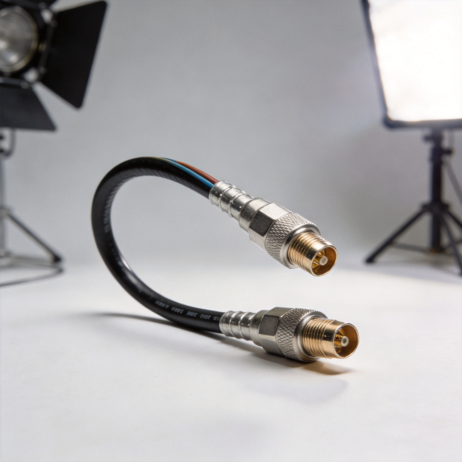
A 30GHz cable assembly is not simply a higher-numbered version of an ordinary coax lead. It is an RF interconnect chosen when the signal path, measurement uncertainty, connector interface, or future operating margin makes a lower-frequency cable a poor fit. For teams working with rf microwave cables, the practical question is not “Can the cable pass a signal?” It is “Can the complete assembly preserve useful performance at the highest frequency, through the required bend, mating, and test cycle?”
From an RF systems perspective, the cable, connectors, and terminations must be treated as one transmission-line component. At microwave frequencies, small discontinuities that are insignificant at lower bands can affect return loss, insertion loss, phase repeatability, and test confidence. A 30GHz-rated assembly is therefore most valuable when the application needs predictable high-frequency behavior rather than a generic connection between two ports.
Start With the Highest Frequency in the Signal Path
The first trigger is straightforward: use a 30GHz assembly when the highest frequency you need to carry, characterize, or validate approaches the upper range of a conventional cable solution. Do not select only by the nominal center frequency. Include harmonics, wideband sweeps, calibration range, and any planned product revisions. If a test setup sweeps to 26.5GHz, for example, specifying an assembly with headroom to 30GHz can be a sensible way to avoid operating at the edge of the cable’s stated range.
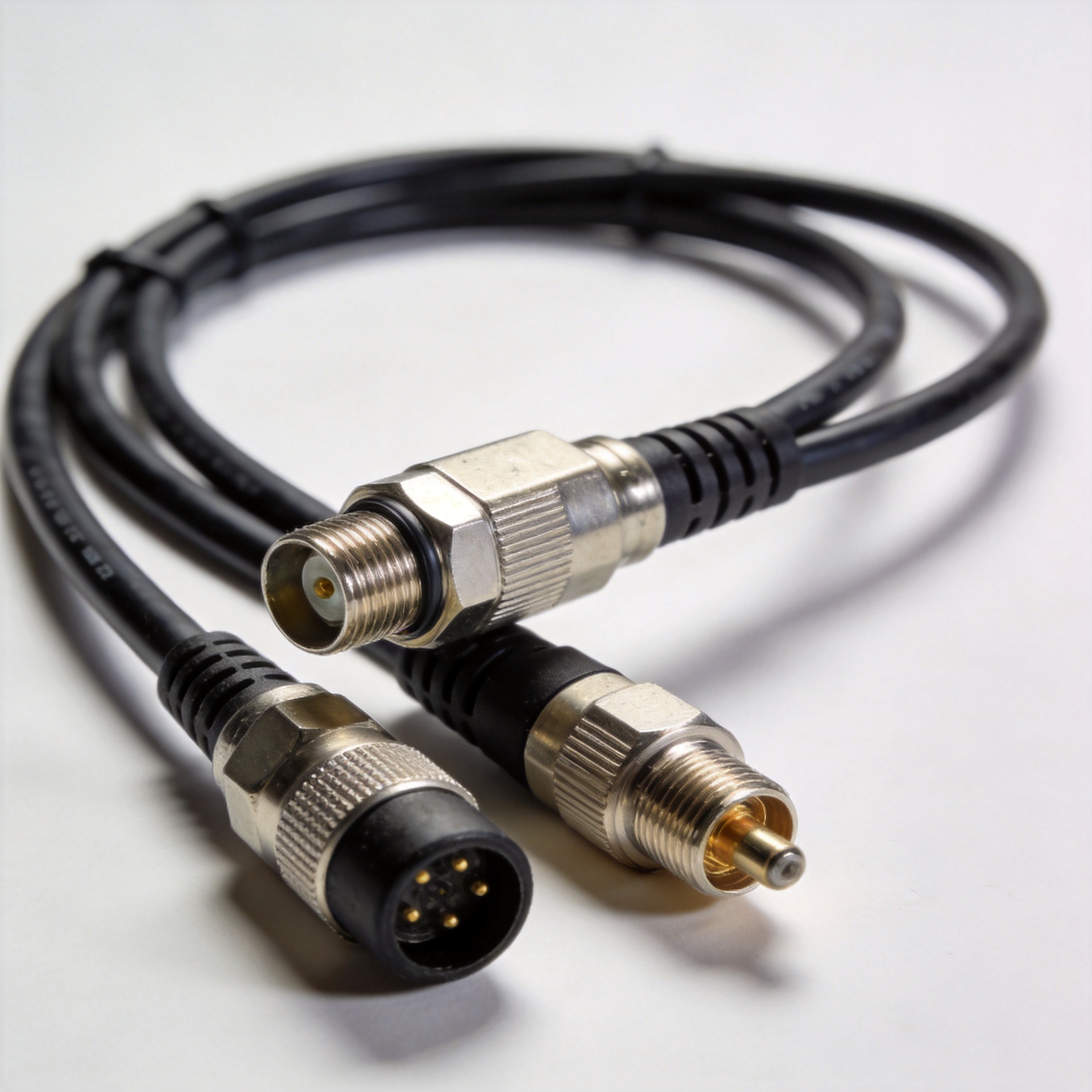
Frequency rating, however, belongs to the whole rf microwave cables assembly. The cable construction, connector series, adapter choices, and termination quality must all support the intended range. Precision 3.5 mm interfaces are commonly used in microwave work and are often specified for mode-free operation to 34GHz, but that connector capability does not automatically make every attached cable suitable for 30GHz service. Review the finished assembly’s published electrical data and the conditions under which it was measured.
Choose 30GHz for High-Frequency Test and Calibration Paths
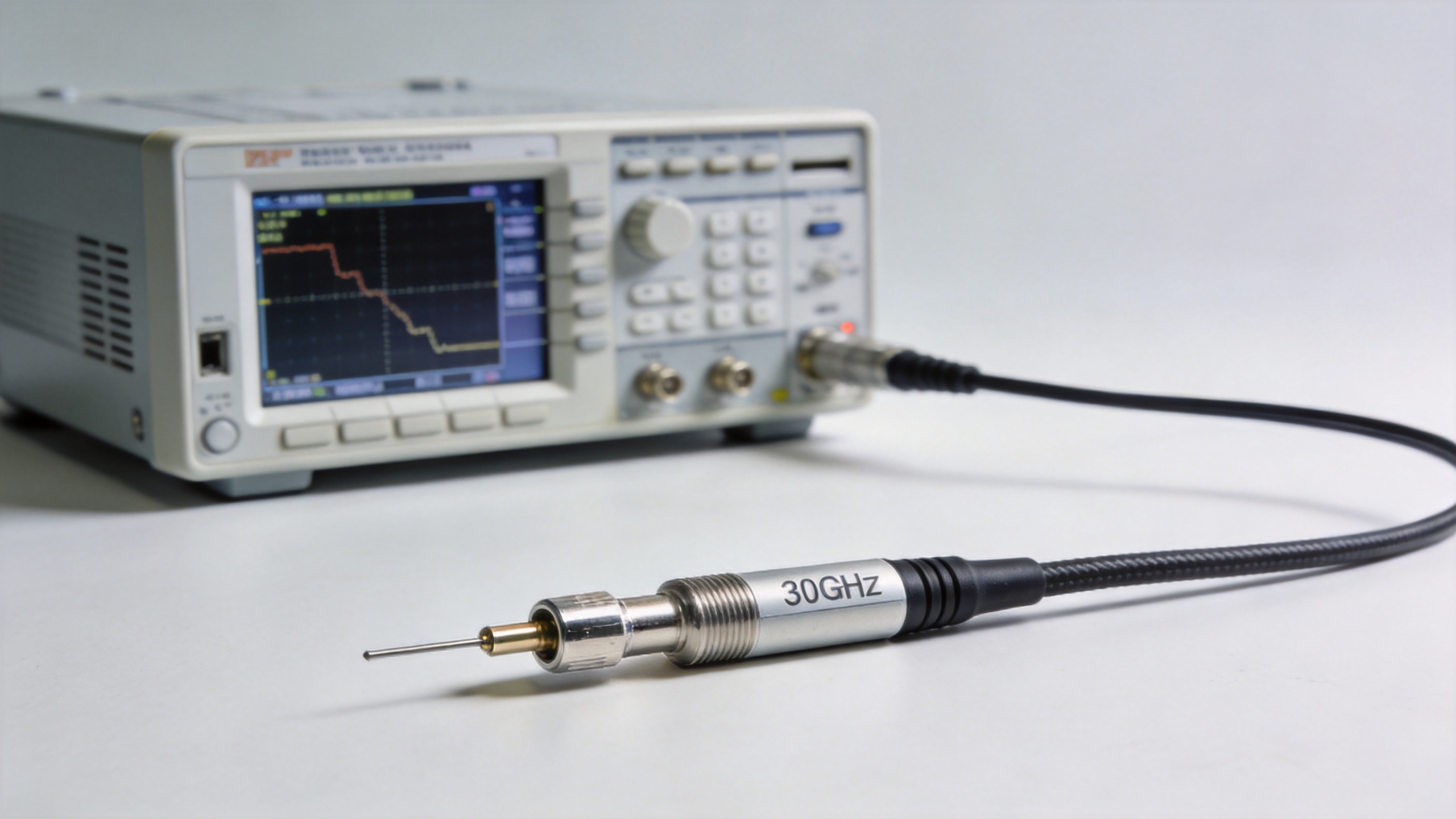
Vector network analyzers, spectrum analyzers, signal generators, antenna test fixtures, and component characterization benches are typical reasons to move to a 30GHz cable assembly. In these environments, the lead is part of the measurement system. A cable that changes significantly after bending or repeated mating can add uncertainty that appears to be a device-under-test problem.
Prioritize phase stability, amplitude stability, return loss, insertion loss, and repeatable connector engagement. Phase stability is especially important where a measurement compares phase over frequency or where several paths must track each other. Temperature change, flexing, and connector handling can all influence repeatability. A well-chosen 30GHz assembly will not remove the need for calibration, but it helps prevent the cable from becoming the least controlled element in the test chain.
- Use a matched, high-frequency assembly for calibration kits, VNA port extensions, and fixture connections.
- Specify the needed connector gender and interface early to avoid stacking adapters.
- Define whether the cable will be static, periodically flexed, or repeatedly handled during production testing.
- Set an acceptance plan for the electrical characteristics that matter to the measurement.
Use It When the System Has Microwave or Compact High-Speed Interconnects
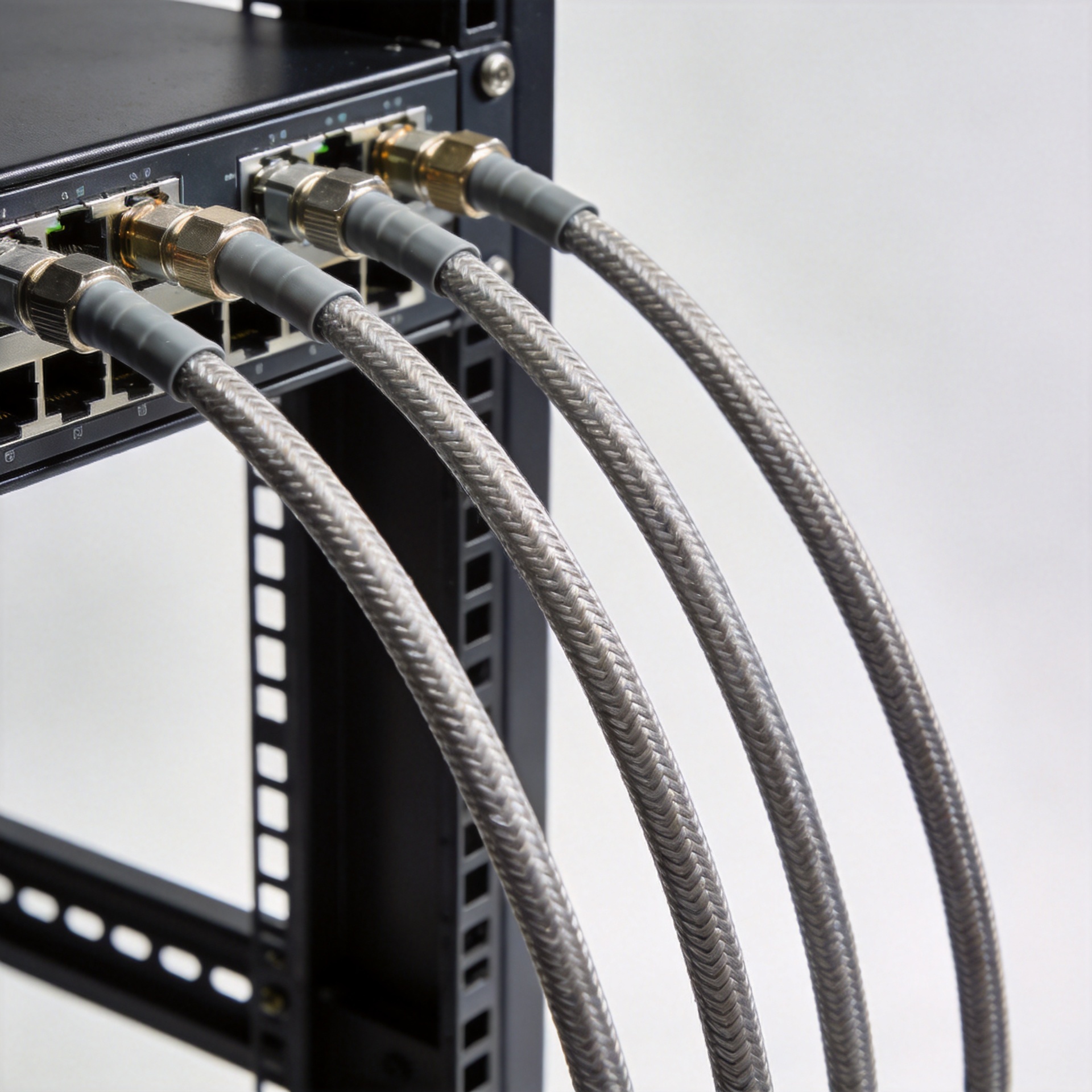
High-frequency communications, microwave radio subsystems, antenna feeds, radar development, and compact laboratory racks can all justify rf microwave cables rated to 30GHz. The need is strongest when the interconnect carries a microwave signal over a meaningful distance, connects tightly spaced modules, or must route through a mechanical enclosure without introducing unnecessary adapters.
At these frequencies, routing is an electrical decision as well as a mechanical one. A tight bend radius, a sharply routed connector, or strain at the cable-to-connector transition can affect the assembly’s long-term behavior. Discuss the available installation space, preferred cable length, required flexibility, connector orientation, and mating-cycle expectation before selecting a build. This is where a custom assembly can be more useful than adapting a standard lead after the fact.
When a Lower-Frequency Cable May Be Enough
A 30GHz rating is not automatically necessary for every RF application. If the system operates well below the cable’s verified upper frequency, has relaxed loss and phase requirements, and does not depend on precision calibration, a lower-frequency option may be appropriate. The goal is to match the interconnect to the system requirement, not to buy bandwidth that is not expected to be used.
Still, avoid making the decision from frequency alone. A lower-band cable can be unsuitable if the test range will expand, if its connector arrangement forces multiple adapters, or if the setup requires frequent movement and stable retest results. Conversely, a 30GHz assembly should be evaluated for its real installation constraints—not only its frequency label.
A Practical 30GHz Cable Assembly Checklist
- Define the real frequency range: Include sweep limits, harmonics, and a reasonable engineering margin.
- Identify the electrical priorities: Decide whether insertion loss, VSWR/return loss, phase stability, shielding, or low PIM is most important.
- Confirm the connector pair: Verify the interface, gender, torque practice, and compatibility across the complete signal path.
- Map the mechanical route: Record length, bend space, connector orientation, cable movement, and strain-relief needs.
- Plan verification: For critical paths, define what will be checked at delivery and after installation.
Specification Review: Questions for RF Microwave Cables
Use this short review before you request a quotation or release a drawing. It turns a broad request for rf microwave cables into a defined engineering requirement.
| Review question | What to define for rf microwave cables |
|---|---|
| Frequency | State the maximum operating and sweep frequency for rf microwave cables. |
| Impedance | Confirm the required system impedance for rf microwave cables. |
| Connector | Specify the interface, gender, and mating condition for rf microwave cables. |
| Loss | Set an insertion-loss target at the relevant frequencies for rf microwave cables. |
| Return loss | Identify the return-loss or VSWR expectation for rf microwave cables. |
| Phase | Decide whether phase-stable rf microwave cables are needed after flexing. |
| Power | Check the operating power and thermal conditions for rf microwave cables. |
| Routing | Provide length, bend, and clearance requirements for rf microwave cables. |
| Movement | State whether rf microwave cables remain static or see repeated handling. |
| Environment | Describe temperature, vibration, moisture, and installation exposure for rf microwave cables. |
| Screening | Define any shielding or low-PIM requirement for rf microwave cables. |
| Verification | Agree on electrical inspection criteria for delivered rf microwave cables. |
For critical test paths, document the calibration method, torque practice, and replacement interval alongside the requirement for rf microwave cables. These details make comparisons between rf microwave cables meaningful and help suppliers identify the right cable family, connector termination, and assembly process. The same checklist also helps a laboratory distinguish a 30GHz requirement from a lower-frequency connection that only needs basic continuity.
Move From a Frequency Number to a Complete Interconnect Decision
You need a 30GHz cable assembly when high-frequency margin and repeatable RF behavior are material to the system or measurement—not merely because “30GHz” sounds more capable. Begin with the signal path and the use case, then specify the complete assembly around electrical, mechanical, and verification requirements.
For projects that need a 3.5 mm to 3.5 mm connection, review the available 30GHz Low PIM 3506 Cable Assembly With 3.5M To 3.5M and confirm the final configuration against your system’s frequency range, routing, and test plan. That approach makes rf microwave cables a controlled part of the design rather than an afterthought.