EN

How to Compare Indoor Omni Antenna Gain for Distributed Antenna Systems
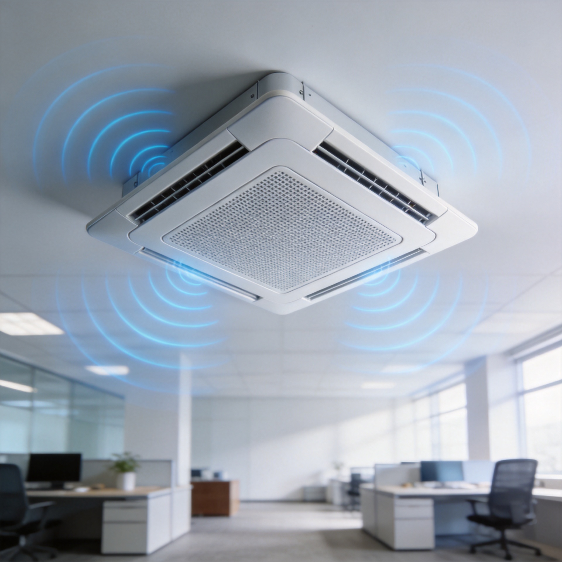
In an indoor DAS, omni antenna gain makes sense only when you read it alongside the coverage pattern and link budget. A larger dBi figure can look like a straightforward upgrade. In a real building, though, it can also concentrate energy closer to the horizontal plane, change the overlap between antenna nodes, and leave less margin where ceilings, partitions, or adjacent floors matter. The useful question is not “Which antenna has the highest gain?” It is “Which combination of gain, pattern, ports, and installation geometry produces a predictable service area?”
As an RF systems engineer, I would compare indoor omni antennas at the same operating band and under the same measurement basis before treating any gain figures as comparable. DAS is designed to distribute signal through multiple antenna points, so coverage uniformity, not headline gain alone, should steer the choice.
Start by making the omni antenna gain numbers comparable
Gain is normally stated in dBi, referenced to an ideal isotropic radiator. That reference is important, but it does not tell you everything a ceiling-mounted antenna will do in a building. Check whether each omni antenna gain value is specified at the same frequency, whether it is peak or typical gain, and whether the data sheet shows a full radiation pattern. A broadband antenna may show different gain across its supported bands; comparing one antenna’s peak point with another’s mid-band value is not a fair selection method.
- Compare frequency by frequency: write down the gain at each band your DAS must support, rather than relying on one headline number.
- Check the test basis: identify peak versus typical figures and request azimuth and elevation plots where available.
- Keep the RF path in view: feeder loss, splitter or coupler loss, connector interfaces, and installed antenna gain all contribute to the effective link budget.
- Use a system target: compare predicted signal level and service margin at the intended user locations, not antenna gain in isolation.
A stated omni antenna gain is therefore a starting input to the design model, not a substitute for it. If two products have similar gain but one has clearer band-by-band data and pattern documentation, the better documented option can be easier to qualify and commission.
Read the elevation pattern before choosing higher gain
An indoor omni antenna aims for broad coverage around its mounting axis, yet “omni” does not mean identical radiation in every three-dimensional direction. As gain increases, the familiar trade-off is a flatter pattern: more energy is concentrated nearer the horizontal plane and less is available above and below it. That can be helpful in a wide, open area with a consistent ceiling height. It can be less forgiving around atriums, stairwells, high ceilings, mezzanines, or floors that rely on vertical spillover.
So, compare omni antenna gain with the planned antenna spacing and ceiling elevation. A slightly lower-gain antenna with a more suitable vertical pattern may create more even overlap between nodes. Conversely, a higher-gain option may be appropriate when modeling confirms that horizontal reach is the constraint and the elevation coverage remains adequate. Neither result is universal; building geometry decides the trade-off.
| Comparison question | Why it matters in indoor DAS | What to verify |
|---|---|---|
| Is gain specified at each required band? | Multi-band DAS performance cannot be inferred from one frequency point. | Band-by-band gain table and operating range. |
| What does the elevation plot show? | Vertical pattern affects coverage near ceiling changes and between floors. | Elevation-plane radiation plot and mounting orientation. |
| How much node overlap is planned? | Uniformity depends on overlap, not just maximum radius. | Predictive design and post-install walk-test plan. |
| What is the total path loss? | Passive components and cable length can offset antenna gain. | Link budget including feeder, connectors, splitters, and couplers. |

Compare coverage uniformity, not only the furthest point
One distant measurement point can look encouraging and still hide a weak coverage plan. That is not the same as a consistent indoor service experience. For offices, transit areas, venues, and multi-room environments, the weak zones between antennas, behind partitions, or at changes in elevation often matter more than the strongest measured range. Use a grid of representative points and review the predicted and measured signal distribution across the service area.
This is where omni antenna gain becomes a system variable. Gain can extend a horizontal contour, but it cannot compensate for poor placement, unsuitable spacing, blocked paths, or an inadequate link budget. In fact, pushing gain upward without rechecking the pattern can make the coverage footprint less balanced. Treat the design goal as controlled overlap with sufficient margin, then select gain to support that goal.
Use omni antenna gain as one input to the coverage model
When comparing omni antenna gain, place every candidate in the same predictive model. Start with the proposed mounting height, then apply cable and passive-path losses, expected traffic areas, wall attenuation assumptions, and the intended overlap with neighboring nodes. This puts omni antenna gain in context: a stronger horizontal contour is useful only if the resulting pattern still supports the target signal level throughout the served zone.
For a two-candidate review, record the omni antenna gain at every required band, compare the associated elevation patterns, and test both layouts against the same acceptance points. If the higher omni antenna gain candidate improves distant horizontal points but weakens edges near a height transition, the lower-gain option or a revised node layout may be the more robust design. This is a coverage decision, not a catalog-ranking exercise.
Evaluate port configuration and MIMO requirements separately
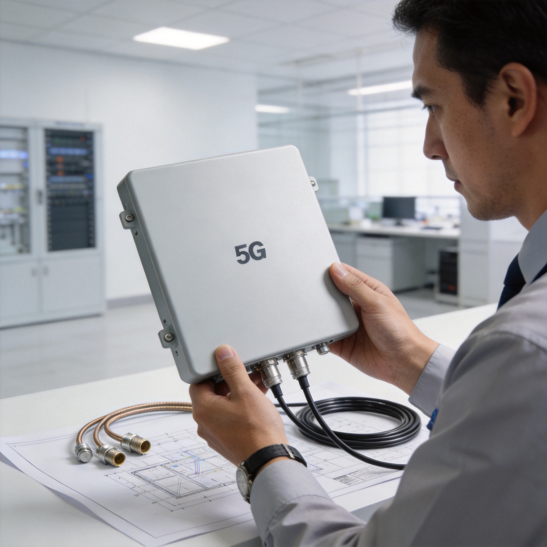
Do not use gain as a shortcut for port configuration. A single-port indoor omni antenna and a multi-port MIMO antenna can serve different DAS architectures even when their published gain looks similar. First map the radio, band, polarization, and capacity requirements. Then confirm the required port count, isolation, connector interface, and cable-routing plan. A multi-port device may reduce the number of physical antenna locations in some layouts, but it also changes how feeder paths, port labeling, and commissioning are managed.
For projects that need a broadband, ceiling-mounted candidate for review, the product record for 380-6000MHz Low PIM Indoor Mimo Omni Antenna With N-Female Connector provides a relevant product category to evaluate against the project specification. Confirm all project-critical electrical and mechanical values directly against the current data sheet and the DAS design; a product title alone is not a complete qualification record.
Include installation constraints in the comparison
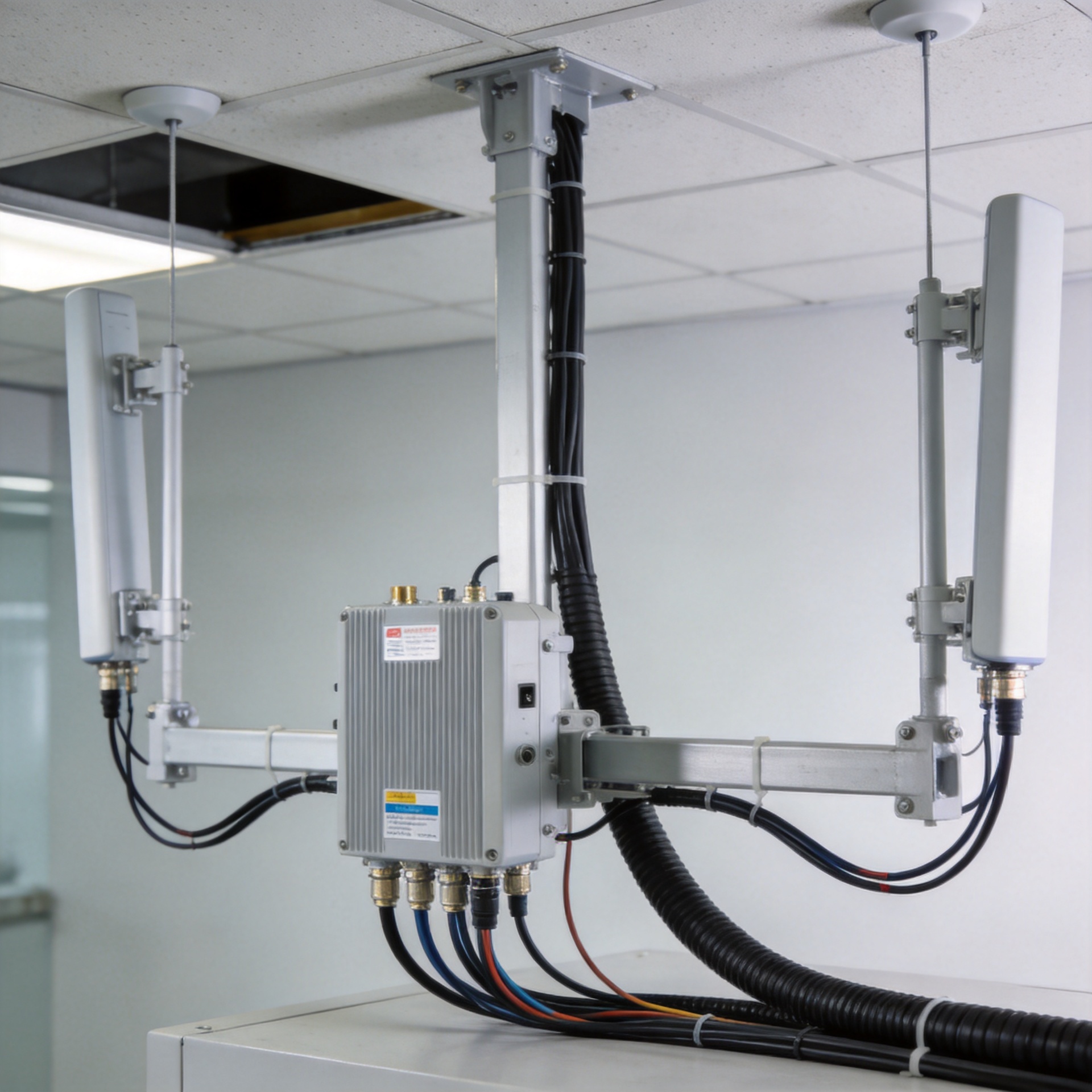
Indoor antenna performance changes after installation. Ceiling material, plenum access, mounting height, nearby metalwork, cable routing, and the final connector condition can all affect the result. Ask practical questions early: Is the antenna clear of obstructions? Can the selected connector and cable assembly be routed without exceeding bend-radius limits? Is there room to identify ports and verify torque during commissioning? Does the installation layout preserve the modeled orientation?
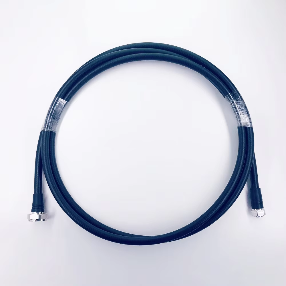
These details matter because the lowest-loss component on paper may not deliver the most reliable installed path. For complex layouts, custom cable assemblies can help match routing length and connector requirements instead of forcing excess cable into crowded ceiling spaces. The goal is not to maximize a single specification; it is to build a repeatable RF path that matches the design assumptions.
A practical indoor omni antenna comparison workflow
- List all required frequency bands, radio ports, and coverage zones.
- Normalize each omni antenna gain value by frequency and measurement basis.
- Compare azimuth and elevation patterns alongside ceiling height and node spacing.
- Calculate the complete link budget, including cable, connector, splitter, and coupler losses.
- Check port count, MIMO architecture, connector compatibility, and installation clearances.
- Model coverage uniformity, then validate it with commissioning measurements at representative locations.
- Document the final antenna, cable, and connector configuration so future maintenance does not break the design baseline.
The strongest comparison is evidence-led: use omni antenna gain to compare like-for-like candidates, verify that the selected omni antenna gain supports the modeled coverage pattern, then let pattern behavior, uniformity, port configuration, and installation reality determine the final choice. That approach gives DAS teams a more defensible specification than selecting the largest dBi number on a product list.