EN

Indoor Omni Ceiling Antenna Design Guide for 5G DAS
Choosing an omni ceiling antenna for a 5G DAS is not simply a matter of selecting a low-profile white dome and placing it wherever a ceiling tile is available. It is a coverage, frequency, installation, and signal-integrity decision. In a modern in-building system, the antenna is the final handoff between the distributed RF network and the people, devices, and rooms that depend on it.
For an awareness-stage project review, start with the system rather than the catalog. A good design asks what bands must be supported, which spaces actually need service, how the ceiling environment changes the radiation pattern, and whether every component in the RF path preserves the low-interference target of the DAS.
What an Omni Ceiling Antenna Does in a 5G DAS
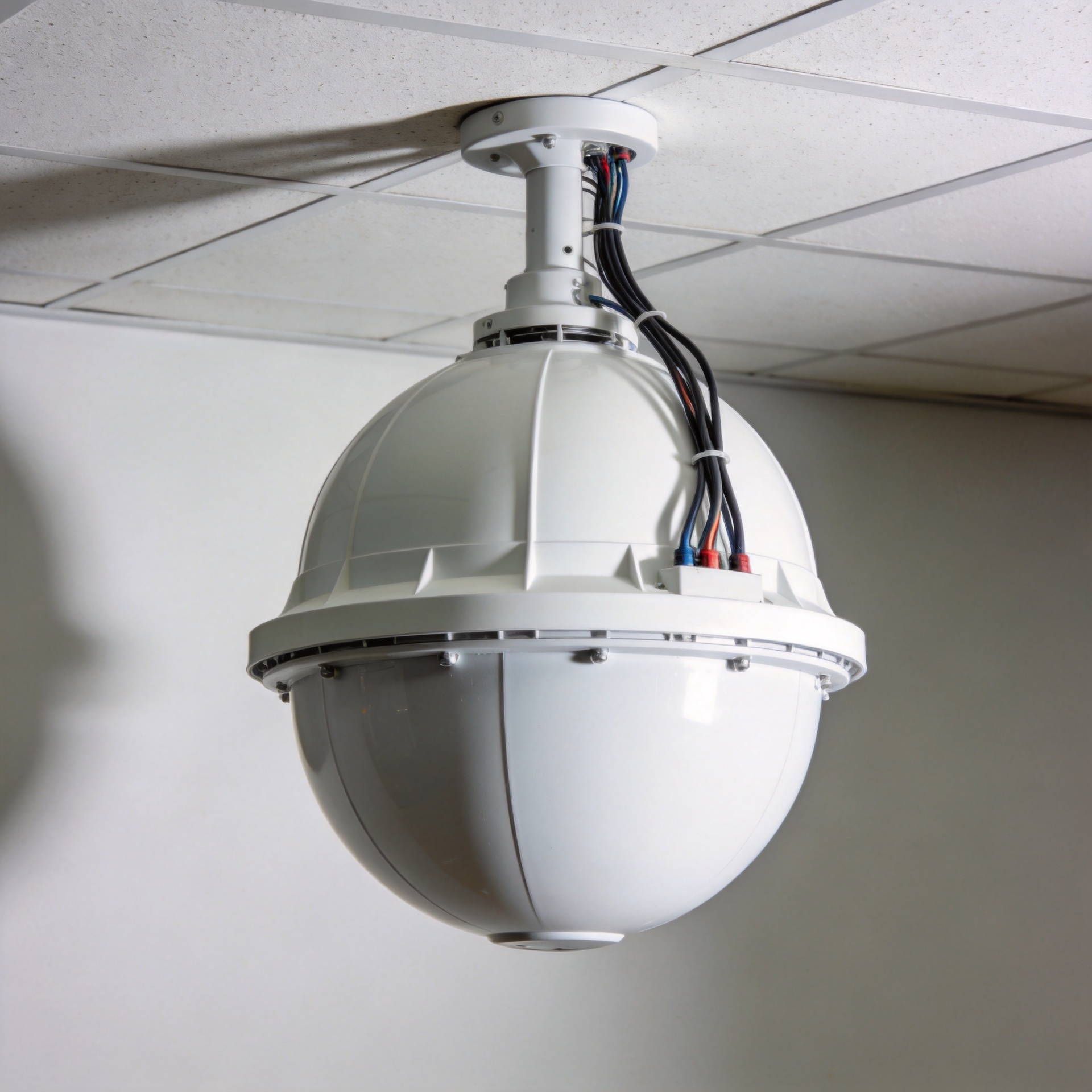
An omni ceiling antenna is an indoor antenna intended to radiate broadly around its mounting point. In a DAS, it is commonly fed by a remote unit, splitter, coupler, or feeder network and used to extend cellular coverage through offices, corridors, retail floors, public areas, and similar interior spaces.
The word omni should be read carefully. It describes broad horizontal coverage; it does not mean identical signal level at every point in a three-dimensional room. Ceiling height, nearby metalwork, concrete, service ducts, partitions, and furniture all influence the effective coverage shape. That is why antenna placement belongs in the RF design process, not only in the installation drawing.
At its simplest, the selection sequence is: identify the bands, model the spaces, place the antenna points, and then verify the complete signal path. The complicating factor is that a design that looks balanced on a floor plan can still underperform if cable loss, connectors, passive intermodulation, or local obstructions are ignored.
Start With Coverage Goals, Not a Generic Spacing Rule
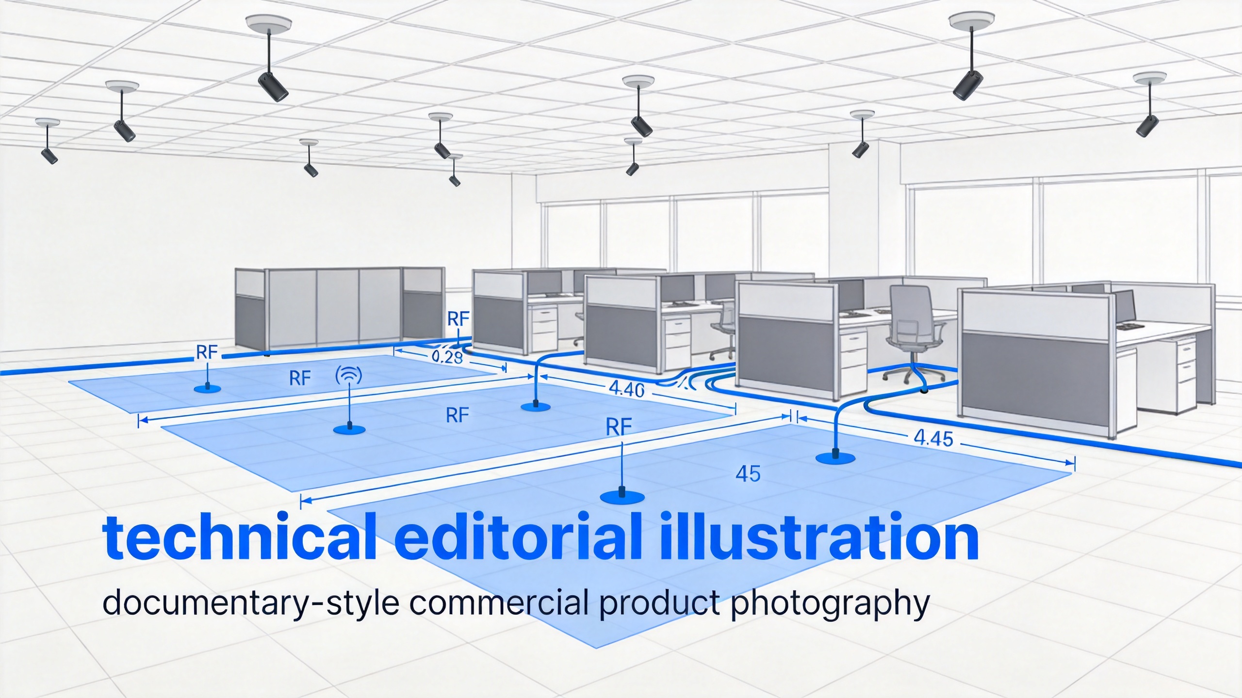
There is no universal spacing number for every omni ceiling antenna. A wide, open lobby and a partitioned office floor may have the same ceiling height but need very different layouts. Begin with the service objective: which carriers or bands are in scope, what signal quality is required, how much user density is expected, and whether the area includes special zones such as meeting rooms, elevator lobbies, stairwells, or equipment rooms.
- Map the usable area: Separate open spaces from rooms with dense walls, glass, shelving, or equipment.
- Check ceiling conditions: Record mounting height, plenum depth, metallic structures, sprinklers, lighting, and access constraints.
- Plan overlap deliberately: Neighboring antenna cells need controlled overlap for continuity, but too much overlap can make troubleshooting and optimization harder.
- Design for the actual user pattern: A lightly used hallway and a high-density conference area should not automatically receive the same antenna treatment.
Here is a question worth asking before finalizing the layout: if one antenna is unavailable after handover, which rooms lose usable service? That question exposes weak coverage dependencies early and encourages a layout that is practical to test and maintain.
Verify the Frequency Range for the Full 5G DAS Band Plan
Frequency range is a selection gate, not a marketing extra. A 5G DAS may need to support legacy cellular bands alongside sub-6 GHz 5G bands, depending on the operators and region involved. Published wideband DAS products illustrate the breadth a project can require; one example family is specified across 698-960 MHz and 1690-5925 MHz. That does not make those bands a universal requirement. It does show why the project band plan must be compared with the antenna specification before procurement.
A matched on-site example, the 380-6000MHz Low PIM Indoor MIMO Omni Antenna With N-Female Connector, can be reviewed as a candidate where its documented range, connector interface, polarization arrangement, and project-level RF requirements align. The title alone is not a complete approval basis; the design team should validate the applicable datasheet and system test plan.
A common assumption is that a higher frequency rating is automatically preferable. It is not, quite. Extra range can be useful for future band changes, but it should not displace the requirements that determine the current project outcome: supported bands, pattern behavior, connector compatibility, installation geometry, and validated RF performance.
Why Low PIM Must Be Managed as a System Property
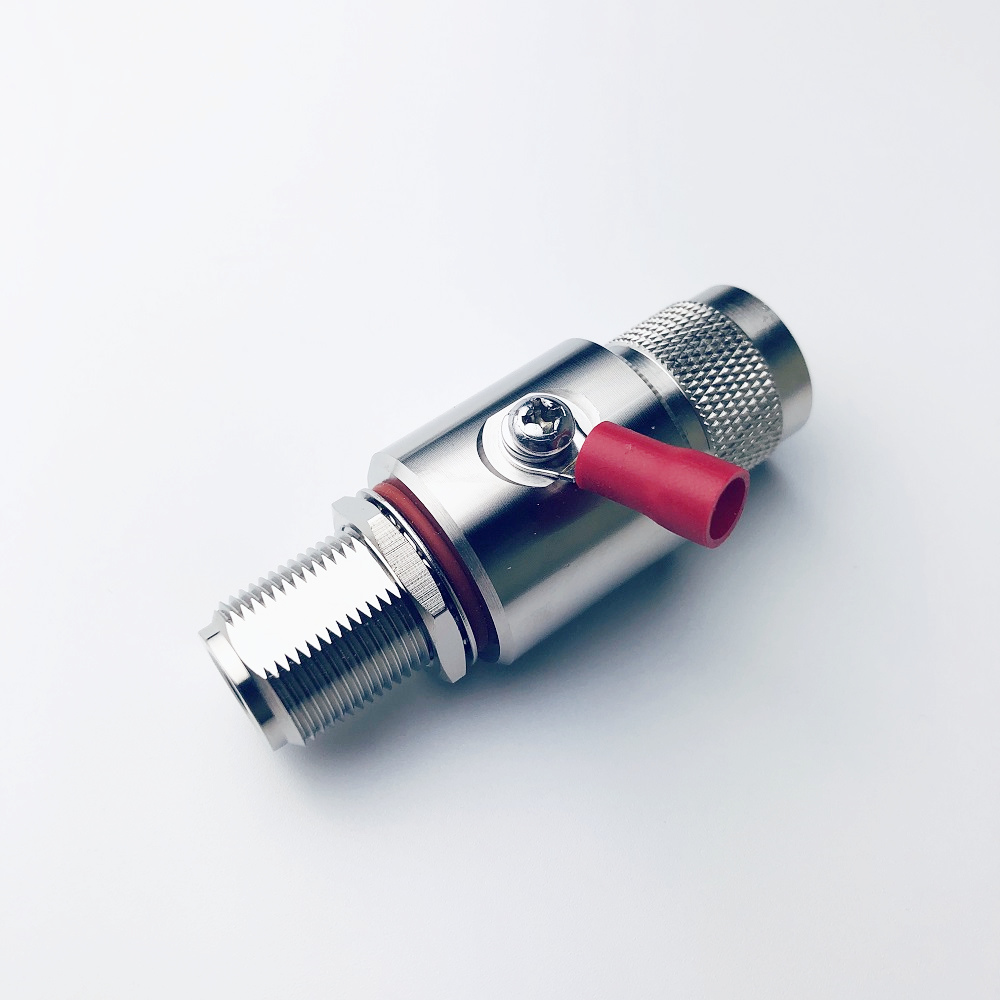
Low PIM is especially important in multi-band, multi-operator DAS environments because passive components can generate unwanted intermodulation products when RF signals meet non-linear contacts or materials. An omni ceiling antenna may be labeled low PIM, but the installed result depends on the entire chain: feeder cable, connectors, adapters, splitters, torque practice, cleanliness, and the antenna mounting environment.
Industry design material for 5G NR DAS highlights that small, low-gain antennas can illuminate external PIM sources. In practical terms, do not limit the review to the antenna body. Inspect nearby metalwork, loose hardware, damaged cable interfaces, and any junction that can create a non-linear contact. Low PIM is not a one-part promise; it is a disciplined installation outcome.
| Design item | What to verify | Why it matters |
|---|---|---|
| Antenna specification | Required frequency coverage and stated PIM test conditions | Confirms the product is suitable for the intended band plan. |
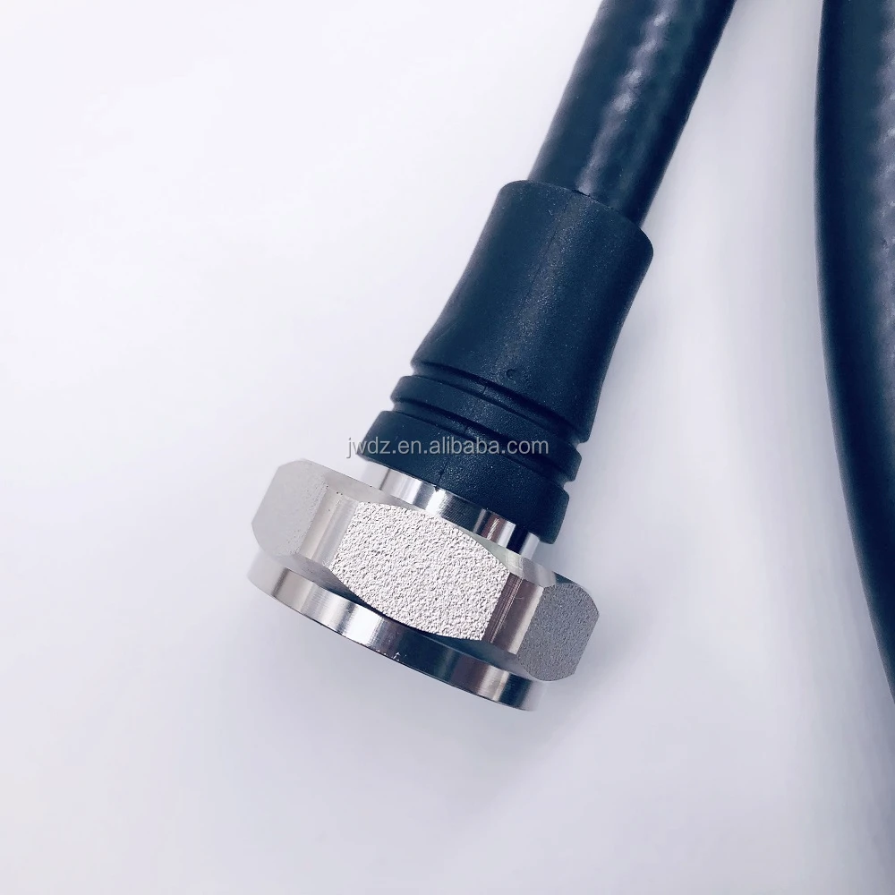
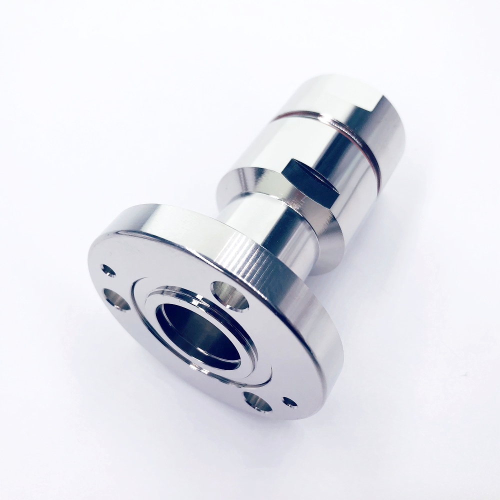
| Connector interface | Correct mating type, clean contact surfaces, controlled torque | Reduces reflection and contact-related PIM risk. |
| Feeder and jumpers | Loss budget, bend radius, routing, and termination quality | Protects the planned link budget and repeatability. |
| Mounting environment | Nearby metal, ceiling materials, access panels, and local obstructions | Helps avoid pattern distortion and external PIM sources. |
Place the Antenna for the Room, Not Just the Drawing
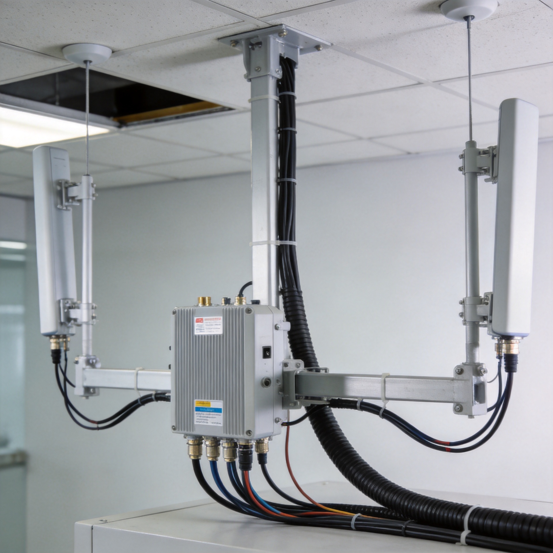
Ceiling placement needs both RF and construction coordination. An omni ceiling antenna installed close to a large metal duct, structural beam, or dense cable tray may not behave like the modeled free-space pattern. Equally, a visually centered antenna may be a poor choice if the high-demand zone is offset by partitions or furniture.
Use the design model to establish candidate locations, then walk the site before release. Confirm that the mounting point is accessible, that the feeder can reach it without exceeding bend constraints, and that future maintenance does not require dismantling unrelated ceiling systems. For a new build, capture this in the installation package; for a retrofit, make it part of the site-survey record.
In a DAS with many interfaces, cumulative connector loss can be as significant as cable attenuation. That is why shortening a cable route is not automatically the only optimization. A clean, serviceable route with fewer unnecessary transitions can be the better system decision.
Build a Practical Validation and Handover Checklist
A reliable indoor DAS is verified after installation, not assumed from its bill of materials. Before handover, use a project-specific test process that covers physical installation and RF performance.
- Confirm every installed antenna location against the approved layout and coverage zones.
- Verify the antenna and feeder part numbers against the approved band plan and BOM.
- Inspect connector mating, torque records where required, cable routing, bend radius, labeling, and strain relief.
- Test the RF path using the project’s defined VSWR, return-loss, PIM, and coverage procedures.
- Record results by antenna branch so future maintenance teams can trace a fault without guessing.
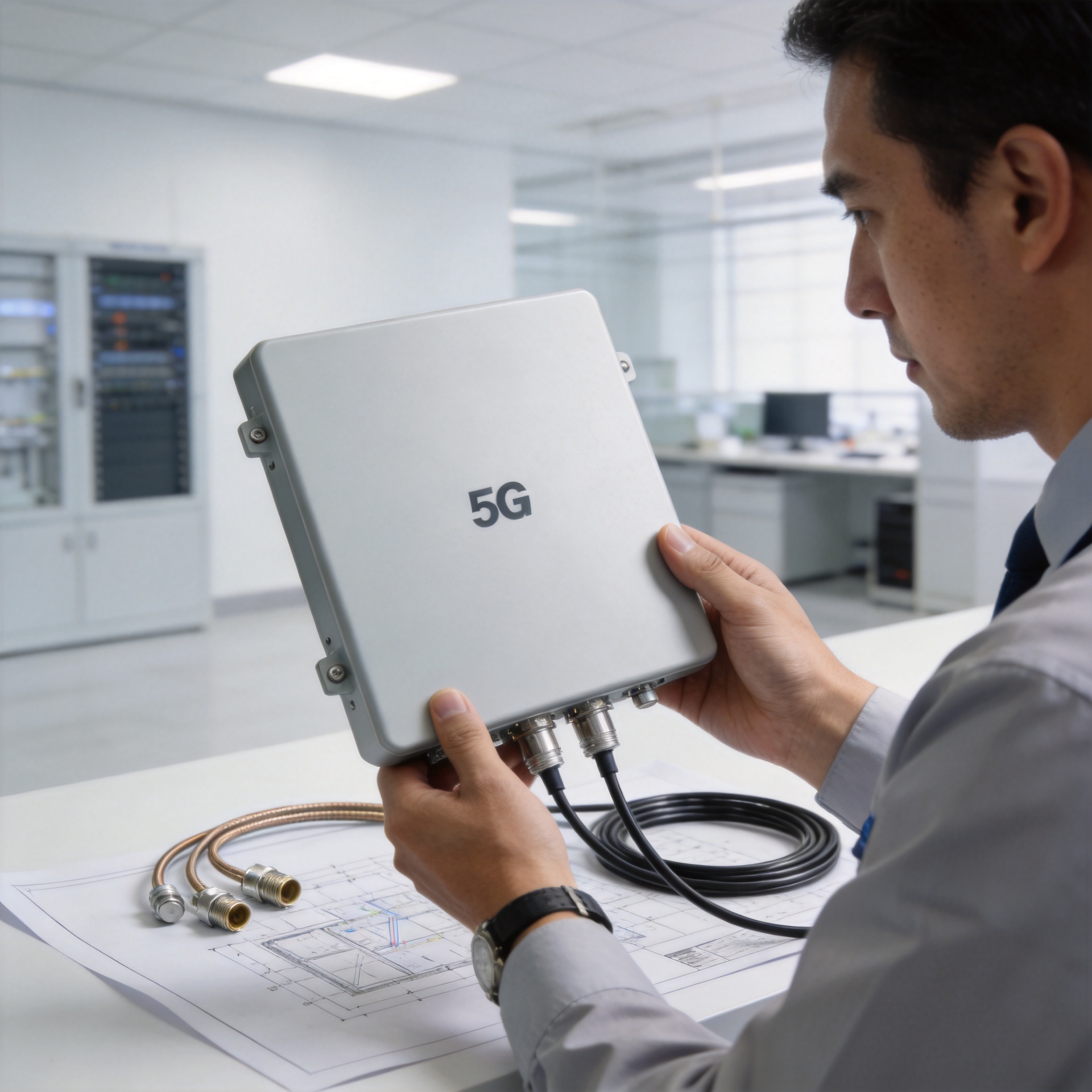
For system integrators and procurement teams, this checklist also clarifies the supplier conversation. A manufacturer with RF interconnect experience can help review interface selection and custom cable assembly needs, but the final antenna layout and acceptance thresholds must remain tied to the building, carriers, active equipment, and approved project design.
A Quick Decision Matrix for Each Omni Ceiling Antenna Branch
Before approving each omni ceiling antenna branch, make the decision traceable. A short branch record should state the intended service area, mounting height, approved bands, feeder path, connector interface, and planned acceptance tests. This turns the omni ceiling antenna layout into a maintainable asset record rather than a collection of ceiling locations.
- Coverage fit: Is the omni ceiling antenna location based on the usable room area and expected obstruction pattern?
- Band fit: Does the omni ceiling antenna specification cover every approved band for that branch, including the 5G allocation actually used on site?
- RF-path fit: Are feeder loss, couplers, jumpers, and connector interfaces included in the same link-budget review?
- Installation fit: Can the omni ceiling antenna and its connection point be installed, inspected, and later serviced without disturbing the surrounding ceiling systems?
- Acceptance fit: Does the project test plan define how the omni ceiling antenna branch will be checked for coverage, return loss, PIM, and labeling completeness?
This is also where consistency matters. A strong individual omni ceiling antenna specification cannot compensate for uncontrolled connectors or undocumented branch changes elsewhere in the DAS. Review the branch as a repeatable assembly.
Final Design Takeaway
The right omni ceiling antenna is the one that supports the approved bands, fits the actual ceiling environment, integrates cleanly with the feeder network, and can be validated as part of a low-PIM DAS installation. Treat every omni ceiling antenna as a system endpoint rather than an isolated accessory. That approach gives 5G DAS teams a clearer path from floor-plan intent to repeatable indoor coverage.