EN

Indoor Ceiling Antenna Installation Factors for Reliable 5G Coverage
Reliable in-building 5G begins long before an indoor ceiling antenna is fitted to a tile. Ceiling-mounted omni antennas can distribute service neatly across offices, retail floors, corridors, and public areas, but their result depends on the whole RF path: the building layout, antenna locations, feeder routing, connectors, and commissioning plan. For an awareness-stage DAS project, the practical goal is not simply to add more antennas. It is to place each indoor ceiling antenna where it can support the intended coverage contour without creating avoidable loss, shadowing, or maintenance work.
A useful starting point is to treat the ceiling plan as part of the RF design. 5G signals can be weakened by concrete, metal, glazing, dense shelving, and service infrastructure. A ceiling location that looks central on an architectural drawing may be a poor radiating point once ducts, cable trays, sprinklers, and structural members are considered. The most dependable projects combine a site survey and coverage model with an installation walk-through before locations are released to the field.
1. Start with the coverage objective, not the ceiling grid
Define the areas that need service, the frequency bands to be supported, expected user density, and the performance target before selecting exact antenna positions. An indoor ceiling antenna is typically an omnidirectional coverage element, so it suits open or moderately partitioned areas. It may not be the right answer for long corridors, loading bays, highly shielded rooms, or spaces separated by heavy walls. Those areas can require a different antenna pattern or an additional node.
Ask a simple question early: where will people use the network, and what sits between that area and the antenna? Concrete slabs, lift cores, metal-backed walls, and equipment rooms change the propagation path. In practice, moving a planned antenna a short distance to clear an obstruction can be more valuable than forcing the original grid location. The design should also account for overlap between cells without assuming that two nearby antennas automatically create better coverage.
2. Choose a mounting point with physical and RF clearance
Once a coverage plan identifies the zone, place the indoor ceiling antenna as centrally as practical within that zone and keep clear space around it. Metallic objects and nearby obstructions can distort an antenna’s radiation pattern and may complicate passive intermodulation control. Ceiling grids, HVAC ducting, cable trays, emergency lighting, signage, and door hardware all deserve a field check before drilling or cutting.
Mounting below a false ceiling or other obstruction is often important because an antenna hidden above metalwork may not radiate as the model assumed. At the same time, technicians need enough access above the ceiling to secure the antenna, service the connector, and inspect the cable. A visually clean installation is worthwhile, but it should not make future testing or replacement unnecessarily difficult.
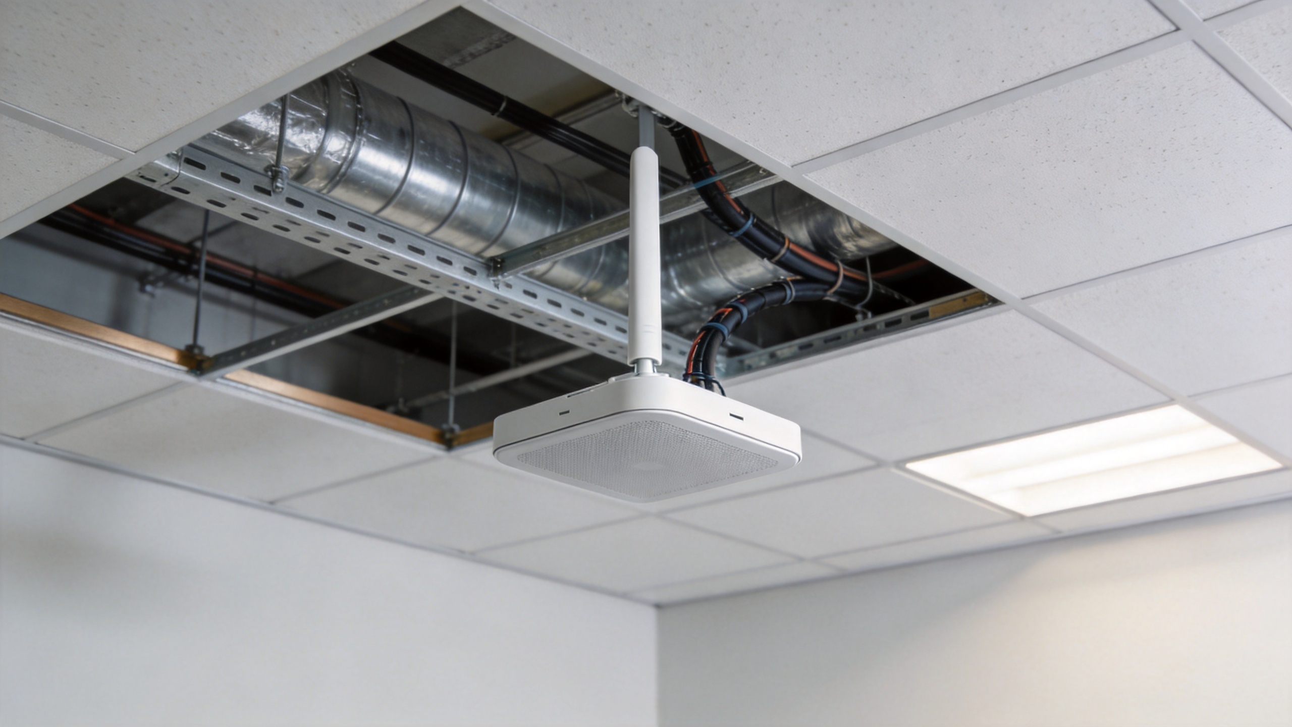
3. Plan feeder routing as part of antenna placement
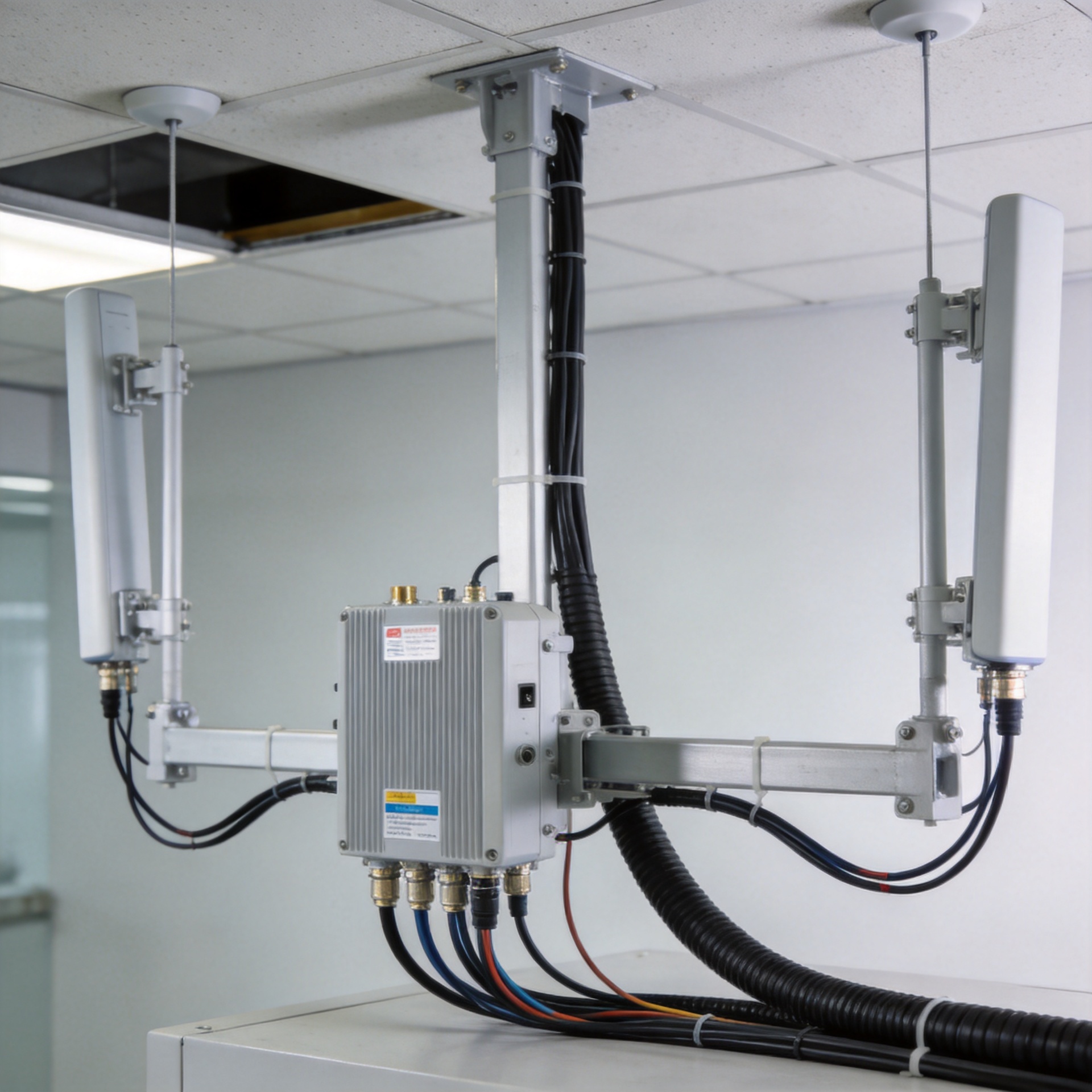
The antenna location and cable route are one decision, not two. A route that requires sharp turns, excessive pulling force, or an improvised detour can compromise a well-chosen antenna location. Keep runs organized, supported, labeled, and protected from pinch points. Follow the cable manufacturer’s specified minimum bend radius and avoid routing that blocks access to ceiling tiles or other building services.
For indoor DAS installations, every connector and transition contributes to the system loss budget. That is why the shortest-looking route is not necessarily the most suitable route; a slightly longer, controlled route with fewer stressed interfaces may be easier to install and validate. Before installation, confirm connector type, gender, torque requirements, and the planned service loop. These details are easy to miss when the focus is only on the visible indoor ceiling antenna.
Where a project needs an antenna intended for broad indoor coverage, the verified product record includes the 380-6000MHz Low PIM Indoor Mimo Omni Antenna With N-Female Connector. Confirm the final frequency plan, interface compatibility, and project-specific electrical requirements against the applicable datasheet before selection.
4. Check the building layout for coverage shadows
Open-plan offices and retail spaces are usually easier to serve than compartmentalized floors. Doorways, full-height partitions, storage racks, elevator lobbies, and changes in ceiling height can create local coverage shadows. Rather than reacting after commissioning, mark these features during the walk-through and compare them with the RF plan.
Think of the indoor ceiling antenna as one point in a distributed system rather than a standalone device. Its useful coverage depends on adjacent antennas, splitter or coupler allocation, feeder loss, and the signal source. This system view helps teams avoid a common mistake: treating a weak area as proof that a single antenna is defective when the actual cause may be location, cable loss, or a coverage assumption made before the interior was complete.
5. Install for repeatable commissioning and maintenance
Good installation practice makes commissioning faster and future maintenance less disruptive. Record the antenna identifier, exact location, cable route, connector interfaces, and test results. Use consistent labels at accessible points so a technician can trace a branch without opening large sections of ceiling. Keep connectors clean, protected, and installed with the specified tools and torque process.
After installation, verify more than whether a handset shows service. The commissioning plan should confirm the signal path and measure coverage in the intended user areas, including likely edge locations. Compare results with the design expectation, investigate anomalies systematically, and document any as-built changes. An indoor ceiling antenna that is correctly mounted but not validated leaves too much uncertainty in a 5G deployment.
Indoor ceiling antenna installation questions to resolve before release
For each indoor ceiling antenna, confirm the intended coverage zone before the mounting point is marked. For each indoor ceiling antenna, confirm ceiling clearance before installation starts. For each indoor ceiling antenna, record the feeder route, connector interface, and accessible service path.
During the walk-through, ask whether an indoor ceiling antenna is near ductwork, metalwork, or a structural feature. Ask whether the indoor ceiling antenna remains below the obstruction that could affect its pattern. Ask whether each indoor ceiling antenna can be reached for inspection without disrupting adjacent building services.
For cable planning, link every indoor ceiling antenna to a documented branch route and label. At commissioning, evaluate each indoor ceiling antenna in its intended user area, not only directly beneath it. If a weak zone is found, review the indoor ceiling antenna location, feeder path, and wider DAS design together.
A project handover should show the as-built location of every indoor ceiling antenna, the associated cable identifier, and the validation record. That documentation lets teams maintain an indoor ceiling antenna installation with confidence when tenants, partitions, or network requirements later change.
Applying the checklist to each indoor ceiling antenna
Use the checklist as a repeatable release process for every indoor ceiling antenna on the floor. Before the crew mounts an indoor ceiling antenna, compare the planned point with the final reflected ceiling plan and the real position of mechanical services. This prevents an indoor ceiling antenna from being installed where a later duct, sign, or partition changes the intended path.
When the cable is pulled, confirm that the branch serving the indoor ceiling antenna follows the approved route and remains identifiable at both ends. The connection at an indoor ceiling antenna should be accessible enough for a controlled inspection, even if the finished space makes it visually unobtrusive. This is particularly useful when an indoor ceiling antenna must be checked after a tenant fit-out.
During acceptance testing, sample each coverage zone served by an indoor ceiling antenna, including doorways, perimeter desks, and locations beside permanent equipment. A measurement near an indoor ceiling antenna is useful, but it does not replace verification in the area that the antenna is meant to serve. Record exceptions so the next review can distinguish a changed interior from an original installation issue.
For expansions, retain enough capacity in the routing and documentation to identify how an additional indoor ceiling antenna would connect. A disciplined record for the existing indoor ceiling antenna locations reduces guesswork during future 5G upgrades and helps engineers preserve the original coverage intent.
Pre-deployment checklist
- Confirm the coverage objective, bands, capacity assumptions, and target areas.
- Walk the site to identify metalwork, ducts, structural elements, and partition changes.
- Verify antenna clearance, mounting access, and the final ceiling height.
- Review feeder paths, bend-radius limits, support points, labeling, and connector compatibility.
- Protect the loss budget by minimizing unnecessary interfaces and using controlled installation practices.
- Complete RF and coverage verification, then preserve accurate as-built records.
Build reliable indoor coverage from the first installation decision
A reliable indoor ceiling antenna installation is rarely defined by the antenna alone. It comes from matching the RF plan to real building conditions, allowing adequate clearance, protecting the feeder path, and validating the finished system. When those factors are considered before deployment, an indoor ceiling antenna becomes a dependable part of a 5G indoor DAS rather than a late-stage coverage fix.