EN
EN

Indoor DAS Explained: Components, Architecture, and Signal Coverage
Reliable cellular service is easy to take for granted until a meeting room, basement, lift lobby, or interior corridor becomes a dead zone. An indoor DAS—an indoor distributed antenna system—addresses that problem by carrying a usable cellular signal into a building and distributing it through many carefully located antennas. Instead of asking one distant outdoor cell site to penetrate every wall and floor, the system creates a controlled RF path closer to users.
For an RF systems engineer, the useful way to understand an indoor DAS is not as a collection of ceiling antennas. It is a signal chain. The chain starts at a signal source, passes through conditioning and distribution equipment, travels over fiber or coaxial cable, and ends at antennas that serve defined indoor zones. Every handoff affects the final experience.
What an Indoor DAS Is Designed to Do
An indoor DAS distributes cellular RF energy across a building, campus, venue, or transport facility. Its goals are coverage, capacity, and consistency. Coverage means users can establish and retain service where it is needed. Capacity means the design can support the expected concentration of users and devices. Consistency means that the experience does not change sharply when someone moves between floors or through high-loss areas.
Building materials make this necessary. Concrete, metalized glass, dense partitions, and below-grade spaces can weaken an outdoor signal long before it reaches an occupied area. An indoor DAS brings the distribution network inside, then uses a planned antenna layout to place signal energy where the link budget calls for it. That is why lobbies, elevators, stairwells, corridors, and enclosed rooms deserve explicit attention rather than being assumed to inherit coverage from nearby open areas.
The Main Indoor DAS Components
A practical indoor DAS is built from several component groups. The exact hardware varies by operator interface and architecture, but the functional roles remain stable.
- Signal source: This can be a carrier-provided base-station interface, a small-cell source, or an approved off-air donor arrangement. It provides the RF or digitized signal entering the system.
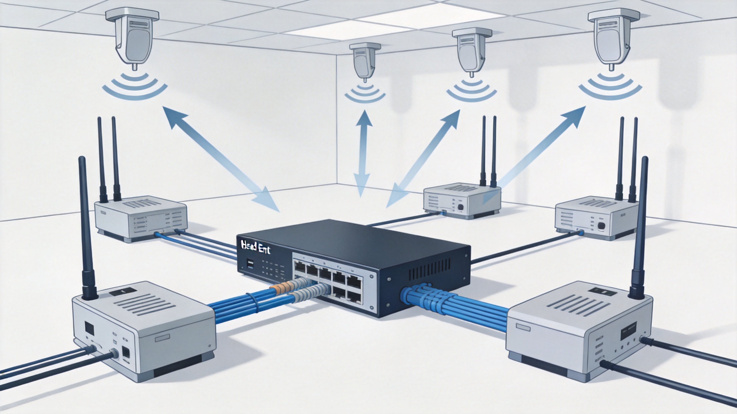
- Head-end equipment: The head-end combines, conditions, converts, or routes signals. In active systems it commonly performs RF-to-optical and optical-to-RF functions.
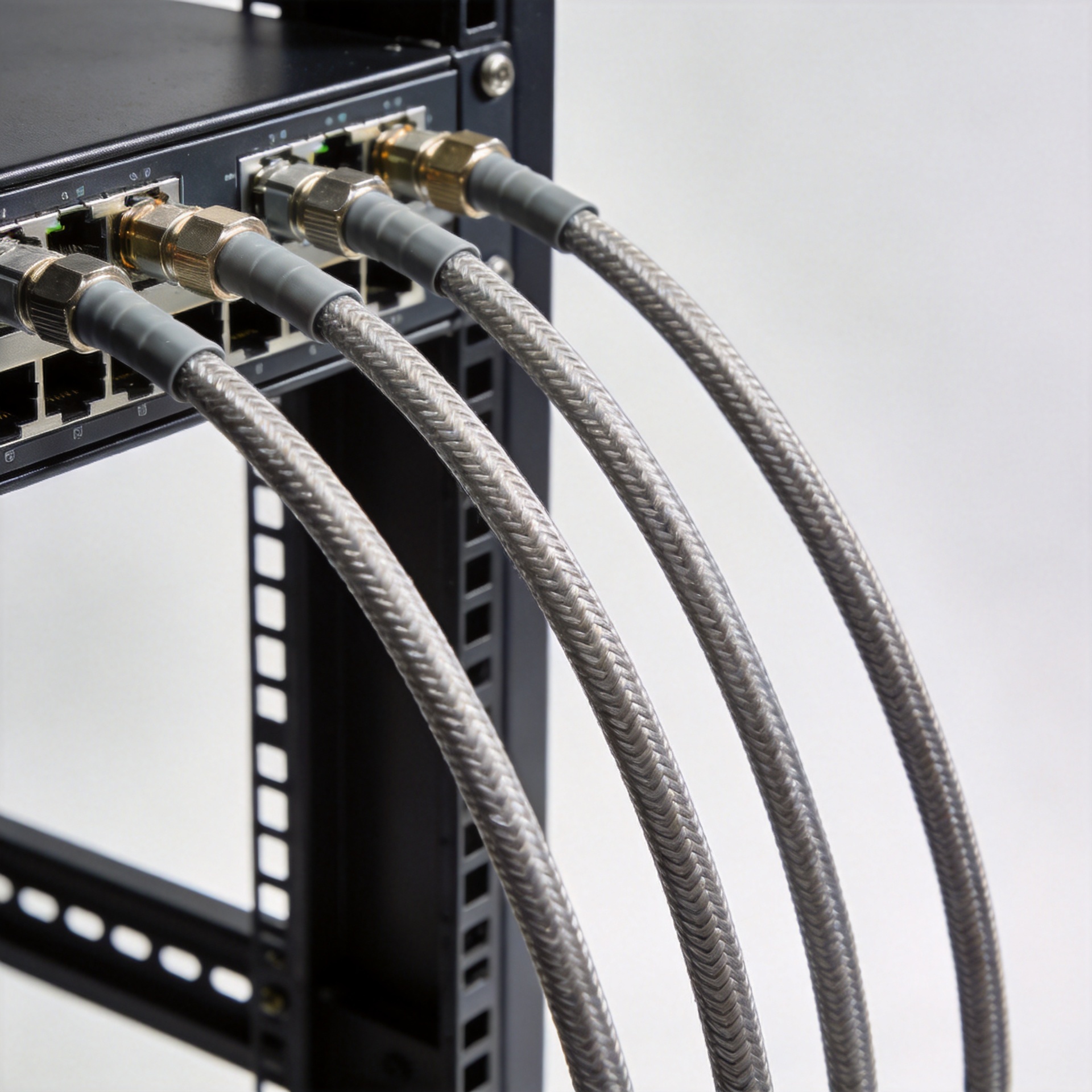
- Distribution network: Fiber, coaxial feeder cable, splitters, couplers, taps, and remote units move the signal toward coverage zones. The chosen medium depends on distance, building size, frequency plan, and architecture.
- Remote units and antennas: Remote units may restore or manage signals near a zone, while indoor antennas radiate energy into the intended coverage area.
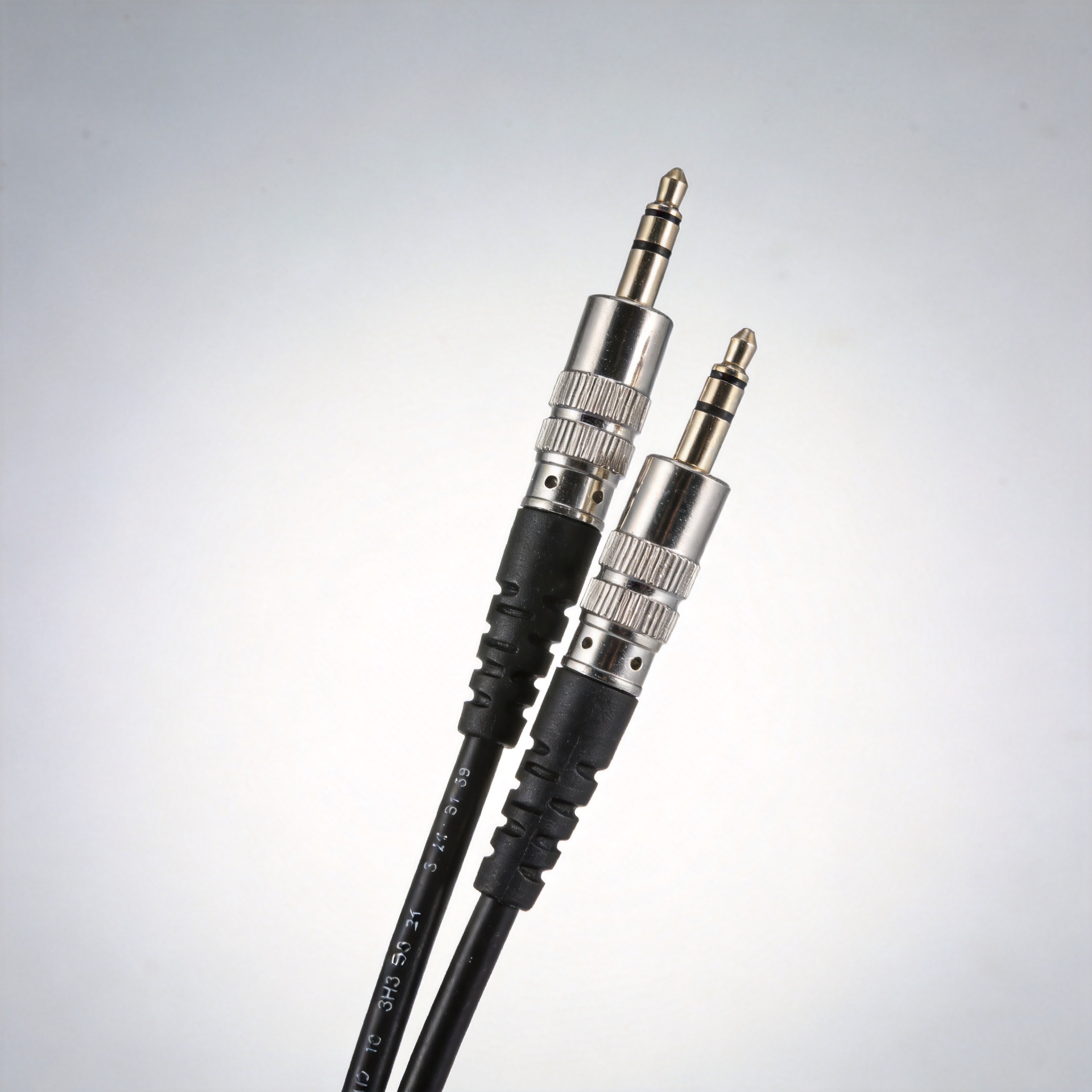
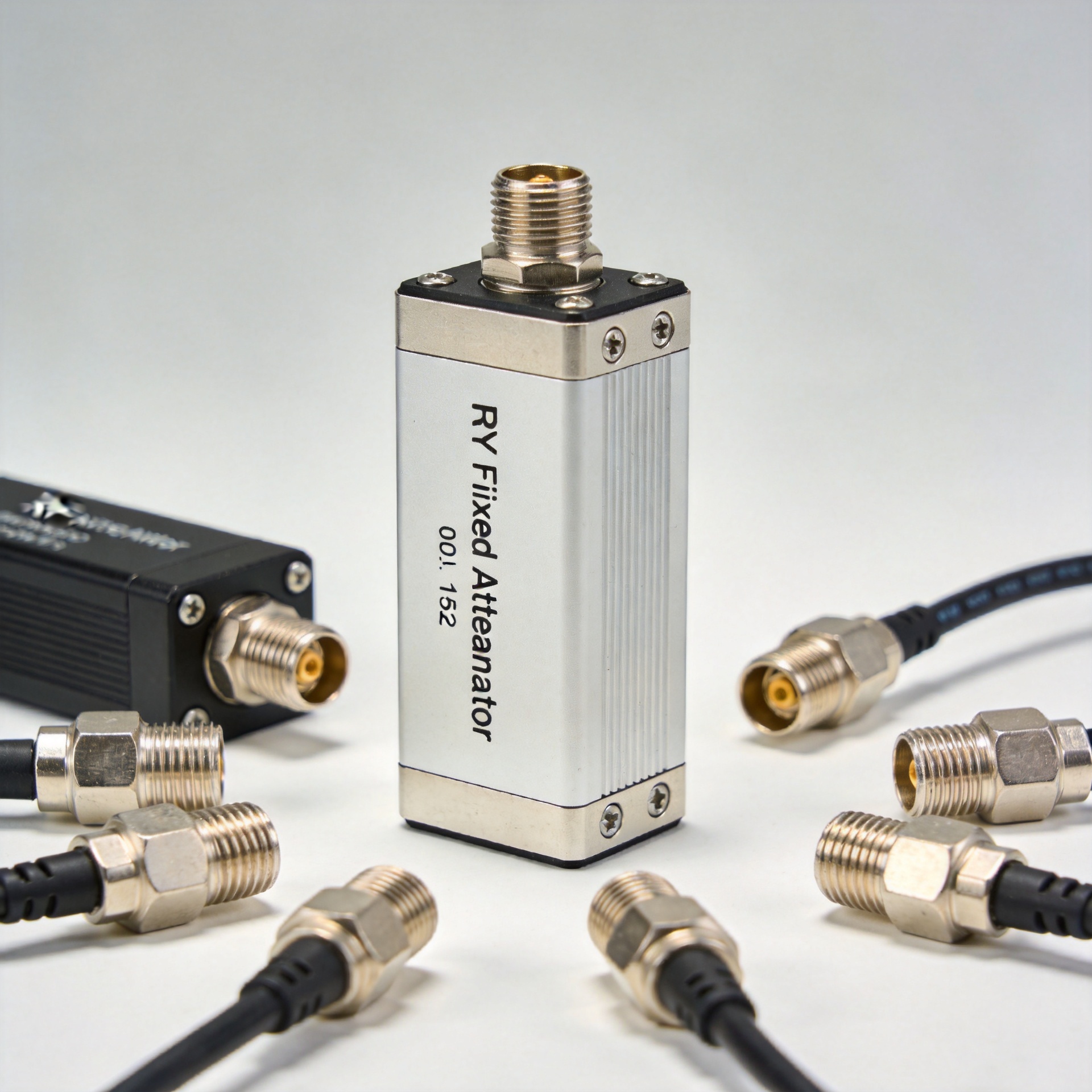
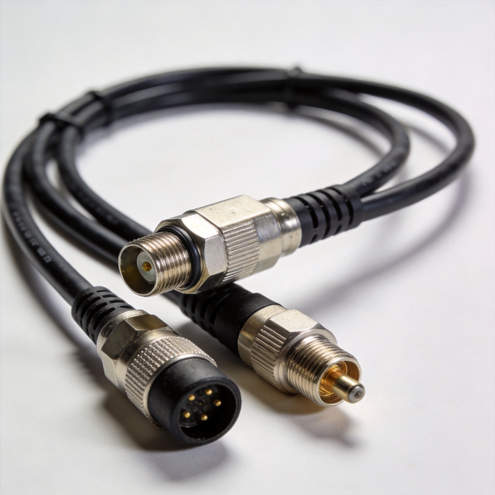
- RF interconnects: Connectors, jumpers, terminations, and cable assemblies join the system. They are small parts of the drawing but not small parts of the link budget.
That final point matters in real projects. A connector or cable that looks acceptable in isolation can still create an avoidable system issue when cumulative loss, return loss, poor mating, or installation damage is repeated across many interfaces. Trace the indoor DAS signal path component by component, and document each transition.
Passive, Active, and Hybrid Architecture
The architecture determines how the indoor DAS distributes signal and where conversion occurs. A passive indoor DAS uses coaxial feeder cable and passive RF components such as splitters, couplers, and taps to deliver signal to antennas. It is often a sensible approach for smaller footprints or shorter cable runs, provided the design can accommodate distribution loss.
An active indoor DAS transports the signal over fiber to remote units, which serve local antenna zones. This approach is useful where distances are longer, the building is larger, or designers need more control over sectorization and expansion. A hybrid DAS uses both approaches: fiber carries the signal through the backbone, while a local passive network feeds nearby antennas. Neither option is universally preferable. If the priority is a compact building with manageable RF loss, passive distribution may deserve more weight. If the priority is a large, multi-floor environment with long backbone paths, active or hybrid distribution usually deserves closer evaluation.
How Architecture Shapes Signal Coverage
Signal coverage begins with a survey and a coverage objective, not with an antenna count. Designers divide the building into zones, identify material losses and high-demand areas, and determine where antennas can be placed without creating excessive overlap or weak pockets. They then calculate the path from the source to each antenna, including cable loss, splitter or tap loss, connector interfaces, and the intended antenna output.
A useful design review asks two questions for every zone: what is the expected signal level at the user device, and what changes when the building is busy? An indoor DAS designed only for a quiet walk test can still disappoint when users cluster in a conference room or public venue. Coverage and capacity should be reviewed together, especially when the system must support multiple frequency bands or operators.
Pay attention to transitions. Floor boundaries, service shafts, fire-rated walls, and long corridors are common places for coverage assumptions to fail. Keep installation records for cable routes, terminations, and antenna locations. When a fault appears later, that documentation can shorten troubleshooting substantially.
RF Distribution Details That Deserve Attention
The physical RF layer is often where a sound coverage design loses margin. Maintain the specified impedance through feeder cables, jumpers, connectors, splitters, and antennas. Confirm connector type, gender, torque practice, cleanliness, bend radius, and labeling before commissioning. A chain with many interfaces can accumulate loss even when each individual component meets its own specification.
For projects that need a wideband indoor antenna option, review the system compatibility and installation requirements of the 380-6000MHz Low PIM Indoor Mimo Omni Antenna With N-Female Connector against the approved design. The product link is a starting point for component review, not a substitute for an RF plan or acceptance test.
Verify Coverage Before Handover
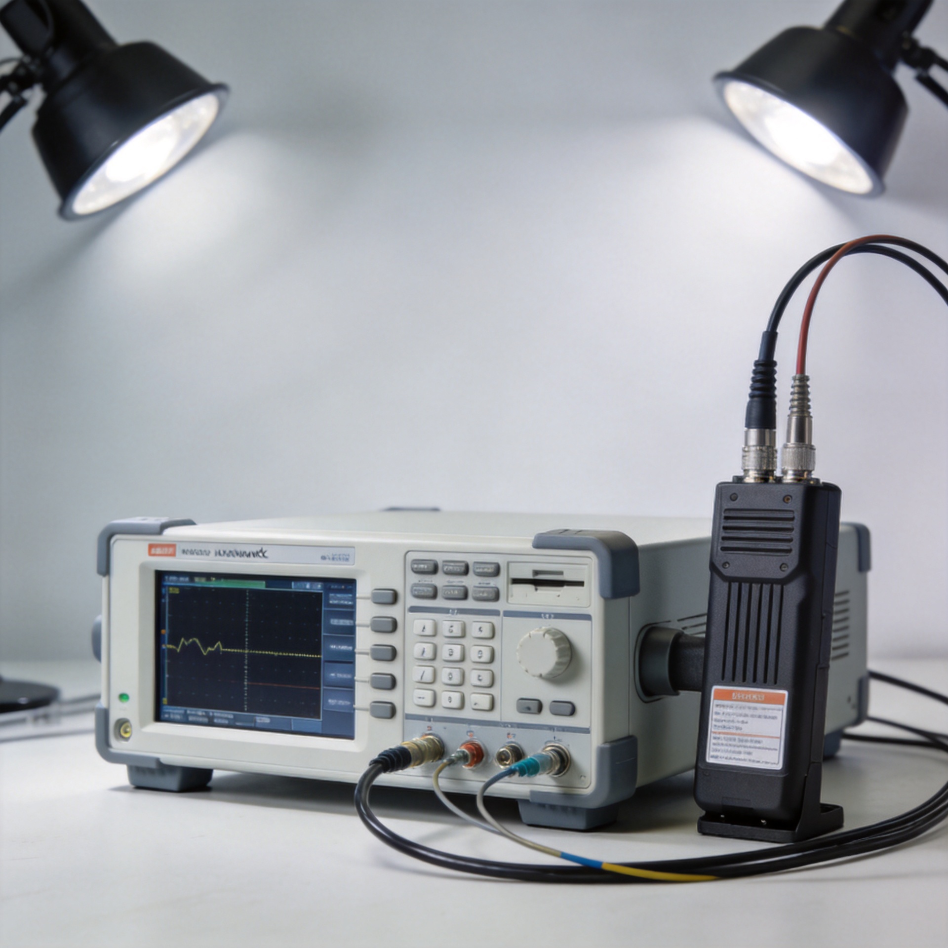
Commissioning turns an indoor DAS design into an operating system. Inspect the installed RF path, confirm cable and connector workmanship, and test the intended zones. The measurement plan should reflect the service objective and the technology in use; it may include received signal strength, quality indicators, throughput behavior, handover performance, and checks in difficult locations such as lifts and interior rooms.
Here is a question worth asking before handover: have you tested the places where users actually report problems, or only the easy open areas? A coverage map is most valuable when it records both passing areas and known constraints. Retest after major tenant changes, renovations, frequency changes, or equipment expansion.
A Practical Indoor DAS Planning Checklist
- Define the service area, user density, bands, and carrier or source requirements.
- Survey building materials, floor plans, risers, equipment rooms, and high-loss spaces.
- Select passive, active, or hybrid architecture based on distance, scale, loss budget, and expansion needs.
- Calculate every RF path, including feeder, passive-device, connector, and antenna losses.
- Plan antenna locations by zone, then review overlap, boundaries, and capacity hotspots.
- Specify verified interconnect components and installation controls.
- Commission, document, and validate the indoor DAS against the defined coverage objective.
An indoor DAS is more dependable when coverage planning and RF workmanship are treated as one engineering task. Start with the user areas, trace the signal chain, and validate the finished installation in the spaces that matter most. That approach produces a clearer architecture, a more defensible link budget, and a stronger basis for reliable indoor service.