EN

5G Omni Antenna Selection: Frequency, Gain, and Installation Factors
Choosing a 5g omni antenna for an indoor distributed antenna system (DAS) is less about finding the highest number on a datasheet and more about matching a complete RF path to the building. Frequency coverage, gain, radiation pattern, cable loss, mounting location, connector interfaces, and the expected traffic profile all interact. A practical selection process starts with the bands in use at the site and finishes with verification after installation.
From an RF systems perspective, the antenna is not an isolated part. Its performance depends on the feed network, connectors, splitters, installation materials, and the local propagation environment. For consideration-stage buyers, the right question is: which antenna specification supports consistent service where people actually use the network?
Start with the frequency plan, not the “5G” label
A 5g omni antenna should support the operator bands and technologies required for the deployment. “5G” does not describe one universal frequency. 5G NR includes FR1 spectrum below 7.125 GHz as well as FR2 spectrum beginning at 24.25 GHz. Most indoor DAS projects use the applicable licensed cellular bands in their local market, often within the FR1 range, but the design team should confirm this from the operator plan and site survey.
Compare the antenna’s stated operating range with the planned bands, including legacy 4G or LTE layers that may share the DAS. Check the entire system path too: feeder cable, jumpers, splitters, and connectors must cover the same frequency window. An antenna with a broad range cannot compensate for a narrow-band component elsewhere in the chain.
- List each operator band required today and the bands likely to be added during the equipment lifecycle.
- Check frequency coverage across the antenna and all passive components.
- For multi-operator systems, confirm isolation and port configuration with the DAS design.
- Do not assume a wideband label means compatibility with every regional 5G allocation.
Balance gain with the coverage shape you need
Gain is important, but more gain is not automatically better for an indoor 5g omni antenna. In an omnidirectional antenna, higher gain is commonly achieved by compressing energy toward the horizontal plane. That can increase reach across a floor while reducing vertical coverage. In a multi-floor building, this may create uneven service if the ceiling height, floor layout, or antenna spacing has not been modeled.
For many ceiling-mounted indoor DAS zones, moderate gain is evaluated because it supports broad, even local coverage. The appropriate value depends on the available input power, desired cell radius, wall and ceiling materials, user density, and the overlap required between antenna zones. Treat gain as part of a coverage calculation, not a standalone purchasing criterion.
| Design condition | Selection focus | Potential risk |
|---|---|---|
| Open office or retail floor | Uniform horizontal distribution and planned antenna spacing | Excess gain can produce uneven overlap |
| Multi-floor interior | Vertical beamwidth and floor-to-floor isolation | Weak service above or below the intended zone |
| Long corridor or outdoor edge | Mounting height, cable loss, and path obstruction | Using an omni where a directional pattern is more appropriate |
Choose the radiation pattern for the actual environment
An omni pattern is useful when users and devices are distributed around the antenna. It is often suitable for interior zones where the system needs 360-degree coverage around a ceiling or central mounting point. It is less suitable when coverage must be concentrated down a corridor, toward one façade, or across a long exterior route. In those cases, a directional antenna or a different placement strategy may provide better control.
Ask the RF team to map coverage areas before finalizing antenna quantities. Site-survey readings, predictive design, and post-installation walk tests should identify shadowed areas caused by concrete, metal partitions, glazing, dense shelving, machinery, or elevator cores. These checks prevent a common mistake: adding gain to solve a placement problem.
Plan installation, cabling, and connector interfaces together
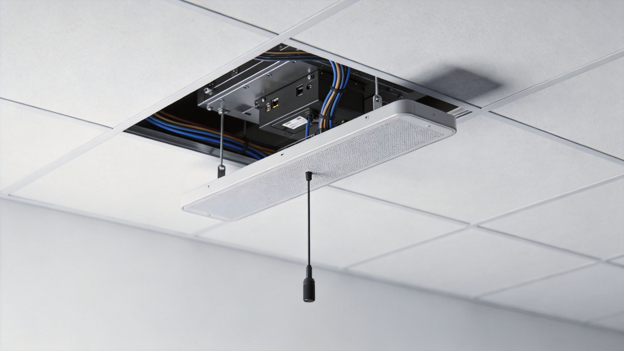
Installation quality can determine whether a 5g omni antenna performs as designed. Select a mounting method that suits the ceiling construction, service access needs, and visual requirements. Keep the antenna clear of major metal obstructions and avoid placing it immediately next to structures that can distort its pattern. Maintain consistent orientation for multi-antenna layouts and document each location for commissioning.
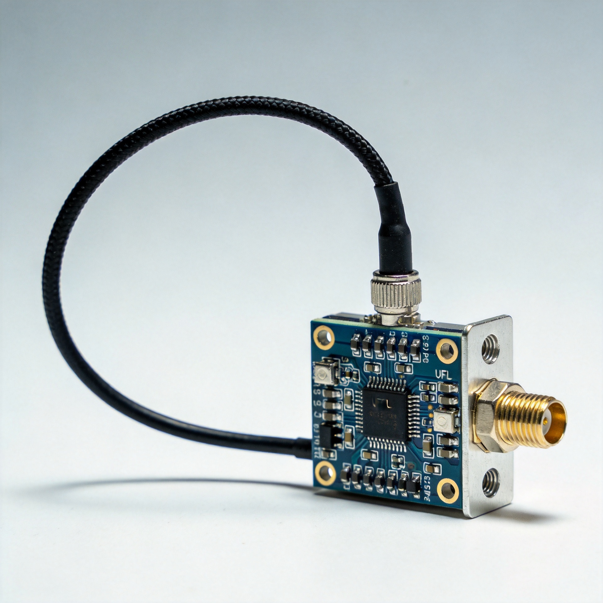
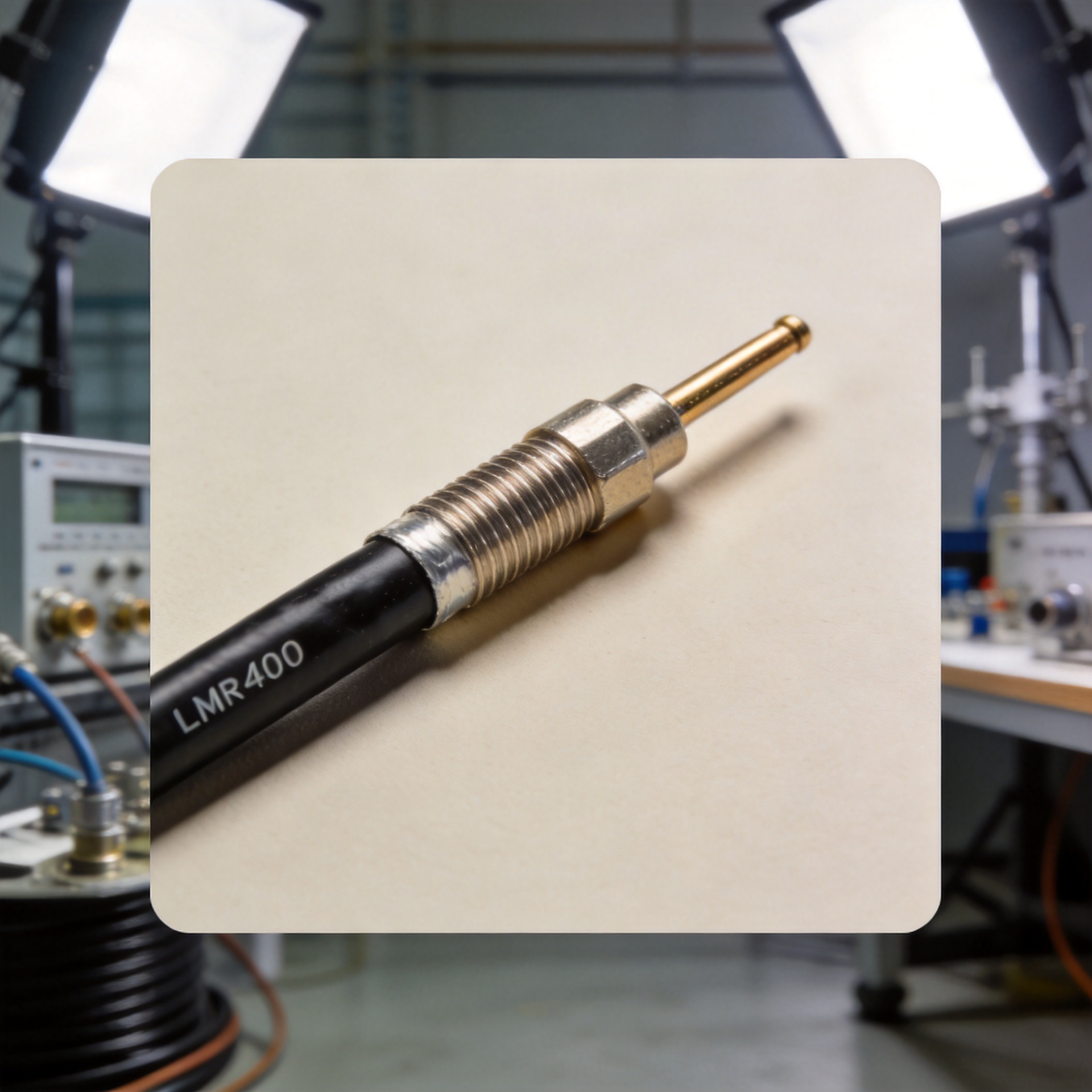
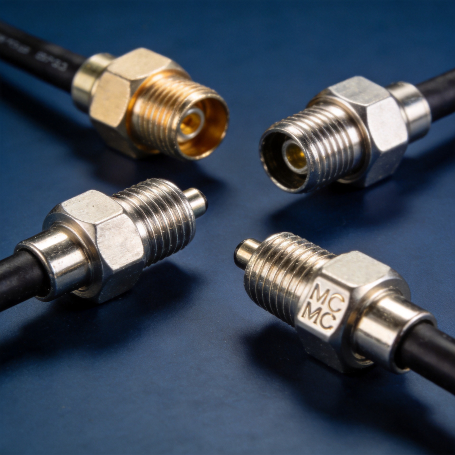
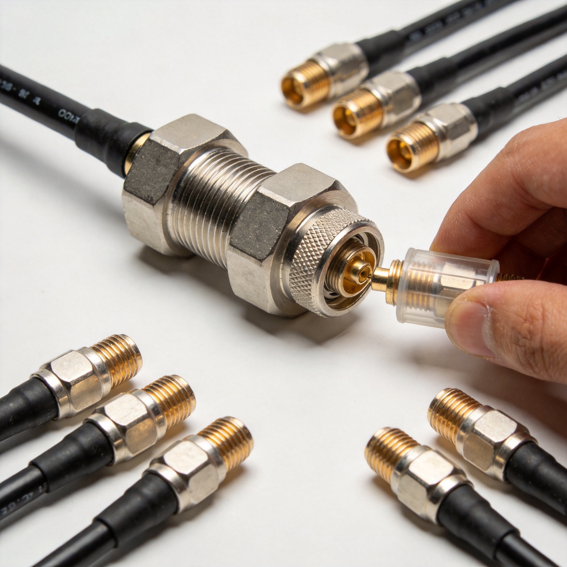
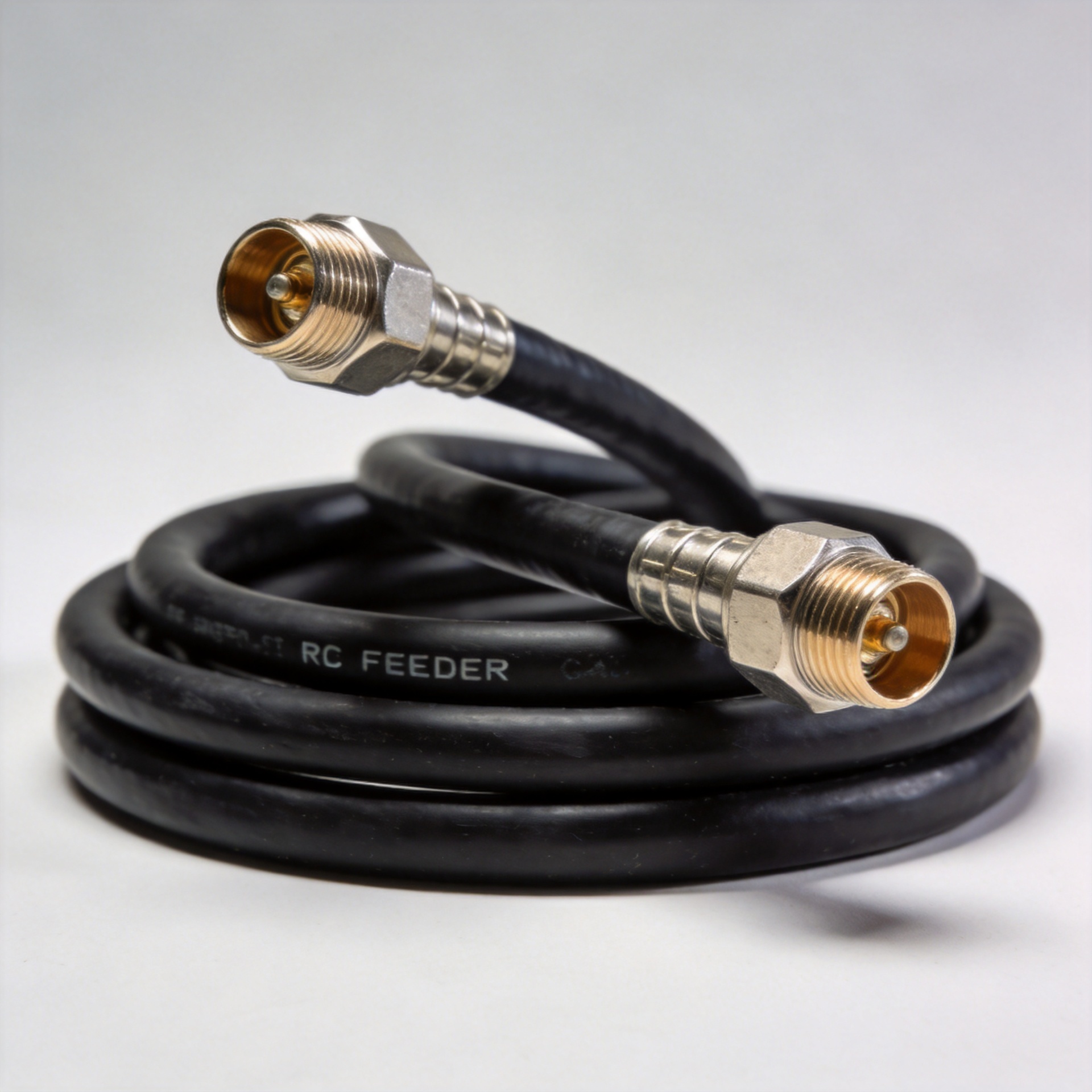
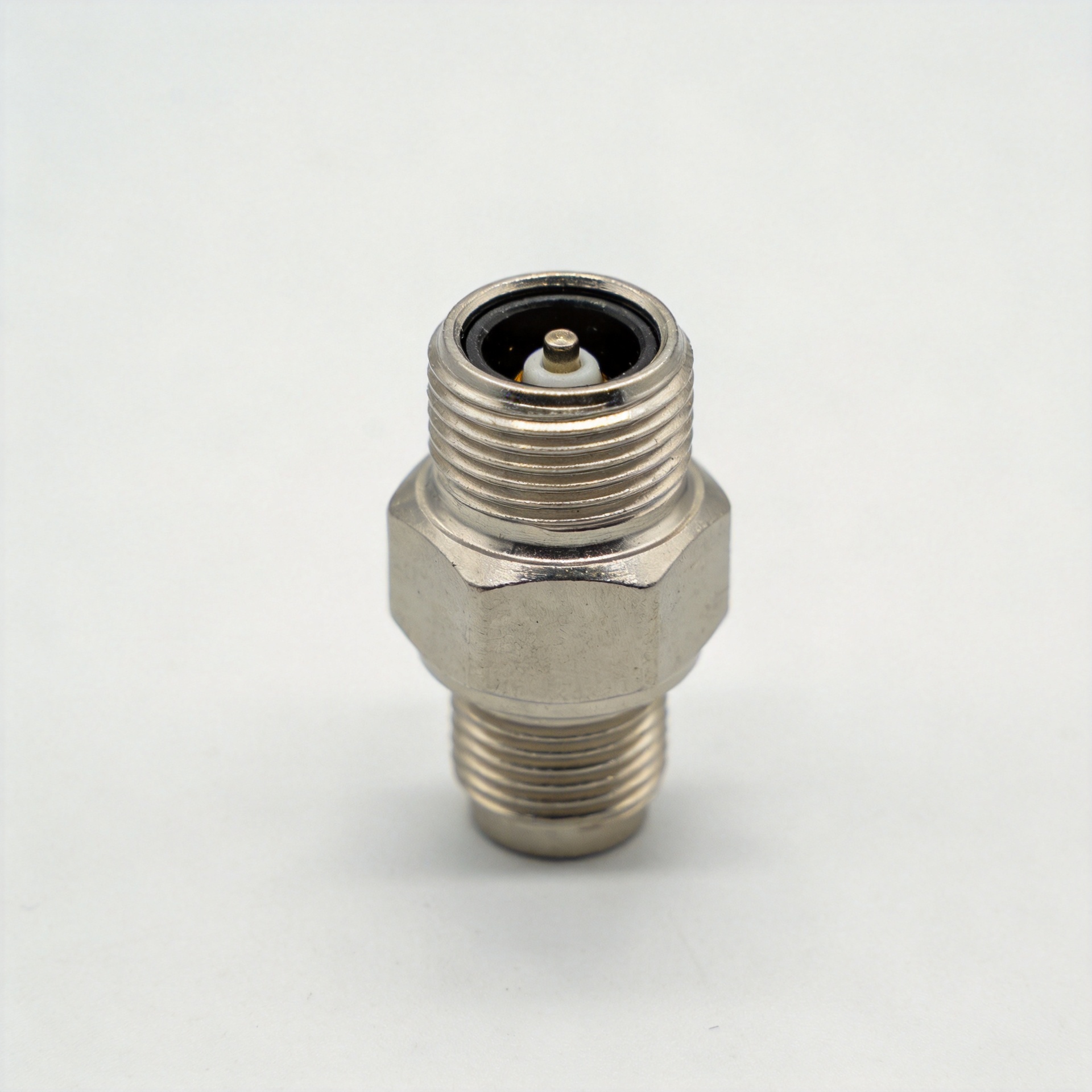
Cable loss must be included in the link budget. Long feeder runs, unsuitable cable type, poor connector installation, or unnecessary adapters reduce the signal reaching the antenna. Confirm connector gender and interface before procurement, then specify installation practices that protect torque, weather sealing where applicable, and PIM performance. Low PIM is particularly relevant where multiple carriers or high-power RF signals share a DAS path.
Consider MIMO and port requirements early
5G capacity and reliability can depend on the radio and DAS architecture, including MIMO requirements. Verify the number of antenna ports, polarization arrangement, and feeder paths against the active equipment design. A multi-port antenna should be selected because its configuration fits the system plan, not simply because it has more connectors.
For an indoor option, review the verified 380-6000MHz Low PIM Indoor Mimo Omni Antenna With N-Female Connector alongside the project’s actual bands, port needs, connector plan, and coverage model. Its confirmed frequency range and N-female interface are useful starting facts, but final suitability still requires a site-specific RF review.
A practical 5G omni antenna selection checklist
- Confirm operator bands, current technologies, and reasonable expansion requirements.
- Check antenna bandwidth against the complete passive RF path.
- Use gain and vertical beamwidth to support the planned coverage geometry.
- Match the omni pattern to the room, floor, or outdoor coverage objective.
- Verify MIMO ports, polarization, connector interfaces, and PIM needs.
- Review mounting materials, cable routes, grounding or weather protection where applicable, and maintenance access.
- Validate the final design through commissioning measurements and walk testing.
5G omni antenna review matrix for DAS teams
Use this short review matrix to keep each 5g omni antenna comparison consistent. Record the required frequency range for the 5g omni antenna, then record the nominal gain for the 5g omni antenna. Next, verify the radiation pattern of the 5g omni antenna against the coverage drawing. Confirm the port count of the 5g omni antenna and the connector interface of the 5g omni antenna before ordering.
During design review, identify the exact mounting point for every 5g omni antenna. Confirm that the selected 5g omni antenna has an accessible cable route. Check whether the 5g omni antenna installation needs a low-PIM passive path. Compare each 5g omni antenna against the same acceptance criteria, rather than comparing only gain figures. This gives procurement, installers, and RF engineers one shared basis for approving a 5g omni antenna.
- Frequency match: Does the 5g omni antenna cover every planned service band?
- Coverage match: Does the 5g omni antenna provide the intended horizontal and vertical pattern?
- Interface match: Can the 5g omni antenna connect directly to the planned feeder assembly?
- Installation match: Can the 5g omni antenna be mounted clear of major obstructions?
- Verification match: Is there a walk-test plan for the installed 5g omni antenna?
When these answers are documented, the 5g omni antenna becomes a controlled part of the DAS design instead of an isolated catalog choice. Reuse the same matrix when a replacement 5g omni antenna is proposed, when a building layout changes, or when a new operator band is added. This helps the team confirm that the 5g omni antenna still supports the design objective after changes in the field.
Make the final decision from the system model
A well-selected 5g omni antenna connects frequency compatibility with usable coverage, rather than optimizing one specification in isolation. Start from the local spectrum plan, use gain to shape—not merely extend—coverage, and treat installation details as RF design inputs. With a documented survey, a consistent component specification, and field verification, DAS teams can make antenna choices that are easier to deploy and easier to maintain.
Questions to resolve before releasing the purchase order
Before a 5g omni antenna is released for procurement, ask the design owner for the current RF plan, the intended antenna locations, and the acceptance measurements. The answer should link the selected model to a specific coverage zone and a specific feed path. If a contractor proposes an alternative, compare the operating range, nominal gain, ports, connector interface, PIM requirement, mounting method, and environmental rating line by line.
It is also useful to document what the 5g omni antenna is not expected to solve. An antenna cannot remove major building attenuation, replace a missing signal source, correct an unbalanced passive network, or create capacity beyond the active system design. Recording these boundaries makes commissioning discussions more efficient and helps prevent changes based only on a single headline specification.
Finally, keep spare and service considerations in the scope. Standardized connector families, traceable cable assemblies, accessible ceiling positions, and a clear as-built record make later testing and replacement simpler. For integrators managing several sites, this discipline can be as valuable as the initial 5g omni antenna selection because it reduces uncertainty when the system is expanded or maintained.