EN
EN

5G RF Jumper Cable Assembly Guide: How to Select the Right Connector and Cable Type for Base Stations
When specifying a harness cable assembly for a 5G base station project, the selection process starts with the installation scenario—not the product catalog. A well-matched harness cable prevents the signal performance issues that are difficult to trace once a site is operational and straightforward to avoid at the specification stage. This guide covers the core criteria: connector interface type, cable diameter, PIM performance, and environmental protection rating.
What Is a 5G RF Jumper Cable Assembly?
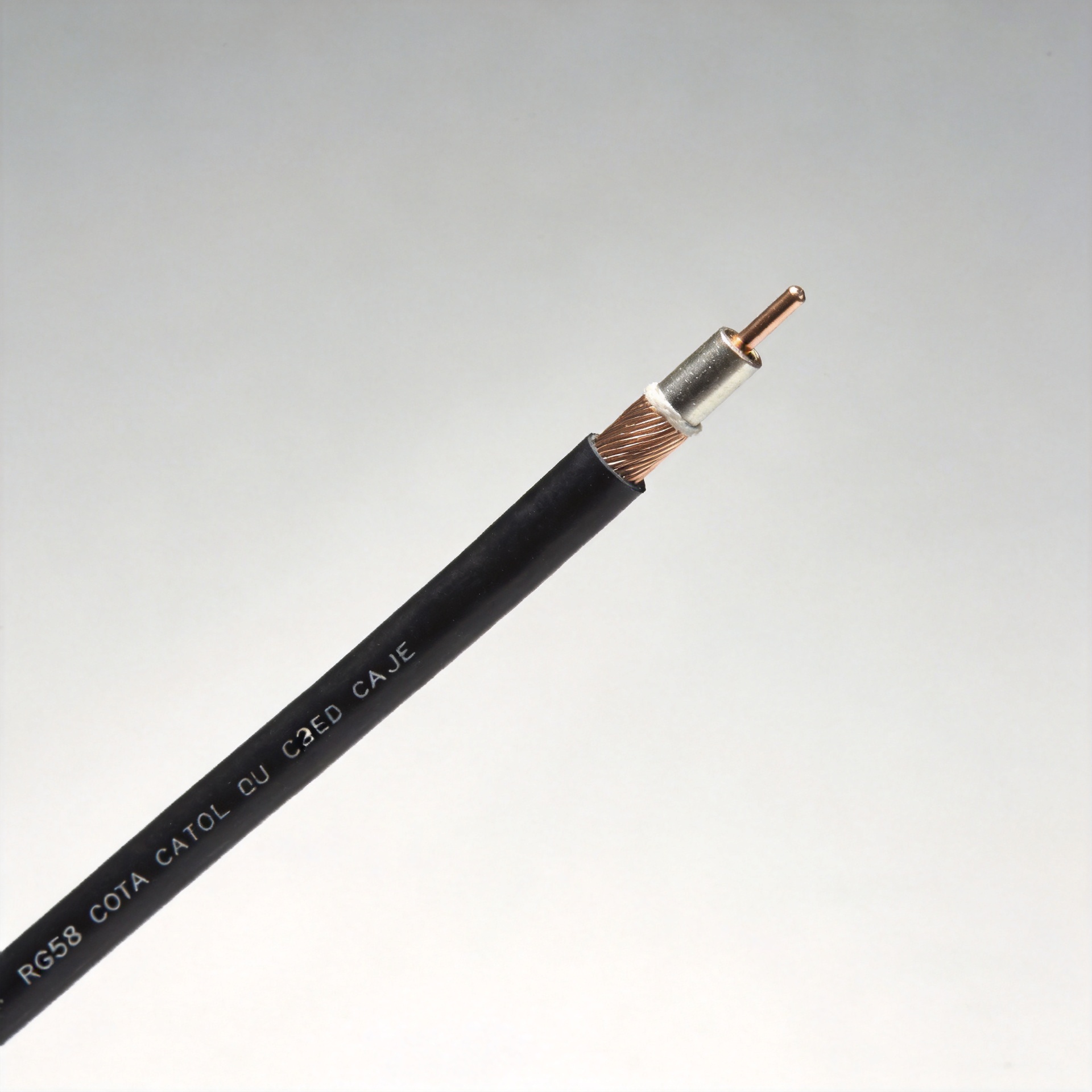
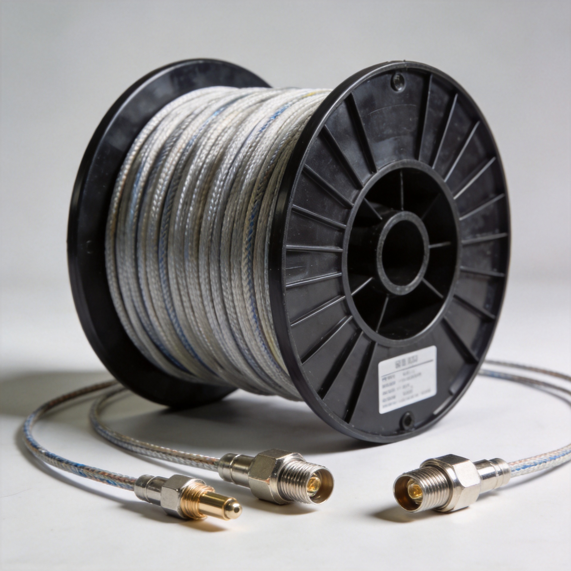
An RF jumper cable assembly—referred to in procurement documents as a cable assy, harness cable, or cable harness assembly—is a pre-terminated coaxial cable that connects antenna ports, radio units, and distribution equipment within a base station. Unlike general wiring harnesses, RF jumper assemblies are precision-engineered to maintain 50Ω impedance, minimize signal attenuation, and meet defined PIM performance thresholds across target frequency bands.
In 5G deployments, these assemblies bridge the radio unit output to the antenna port or diplexer. A substandard cable harness assembly at this position introduces insertion loss, reflected power, or intermodulation products that degrade adjacent carriers. These problems take time to locate in a live system.
Connector Interface Types: 4.3-10 vs. 7/16 DIN
Two connector standards dominate 5G base station RF jumper cable applications. The right choice depends on site type, space constraints, and interface compatibility with existing equipment.
4.3-10 Connector
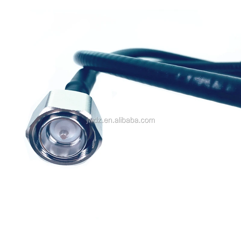
The 4.3-10 is a 50Ω multi-purpose RF connector developed to replace the larger 7/16 DIN format in compact base station architectures. Operating from 100 MHz to 6 GHz with a low VSWR of approximately 1.4, its mechanical profile is roughly 30% smaller than 7/16 DIN—an advantage in high-density antenna configurations where cable routing space is limited. Low PIM is a core design requirement: certified harness cable assemblies using 4.3-10 connectors typically achieve better than -150 dBc at 2×43 dBm, which is the standard threshold for 5G multi-band deployments.
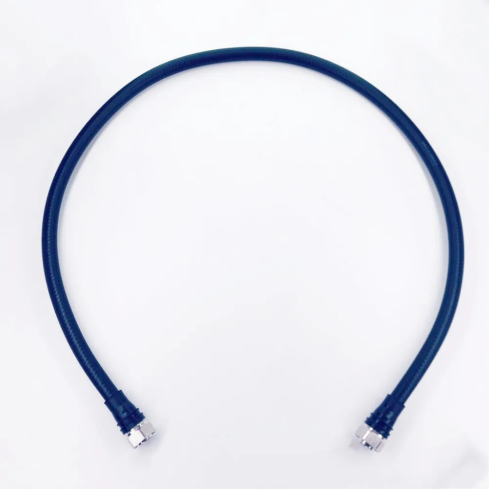
For compact 1/4" cable assembly applications meeting low-PIM specifications, the Factory Low PIM 5G Cable Assembly MINI DIN 4.3-10 Male to 4.3-10 Male For 1/4 Cable represents a format increasingly specified for high-density antenna systems where connector footprint and PIM performance are both constrained.
7/16 DIN Connector
The 7/16 DIN remains appropriate for macro base station installations requiring high-power operation, longer feeder runs, or compatibility with legacy infrastructure. If you're integrating a new cable harness assembly into a site with existing 7/16 DIN interfaces, maintaining that standard avoids mixed-interface configurations that add adapter loss and complexity. The practical selection is usually clear: new 5G compact sites specify 4.3-10; macro sites and high-power applications stay with 7/16 DIN.
Cable Types: 1/4" Super Flexible vs. 1/2" Low Loss
After selecting the connector interface, the cable diameter decision depends on the trade-off between bend flexibility and insertion loss. Installation geometry typically makes this choice straightforward.
1/4" Super Flexible Cable
Quarter-inch super flexible cable is designed for tight-radius routing in congested equipment spaces, including behind panels, within tower enclosures, and in active antenna unit installations where sharp bends are unavoidable. Supporting operation up to 6 GHz, this cable harness assembly format handles the routing adjustments during commissioning without connector stress or cable kinking. For jumper lengths under 3 meters where routing flexibility is the primary constraint, 1/4" cable is the standard choice.
1/2" Low-Loss Cable
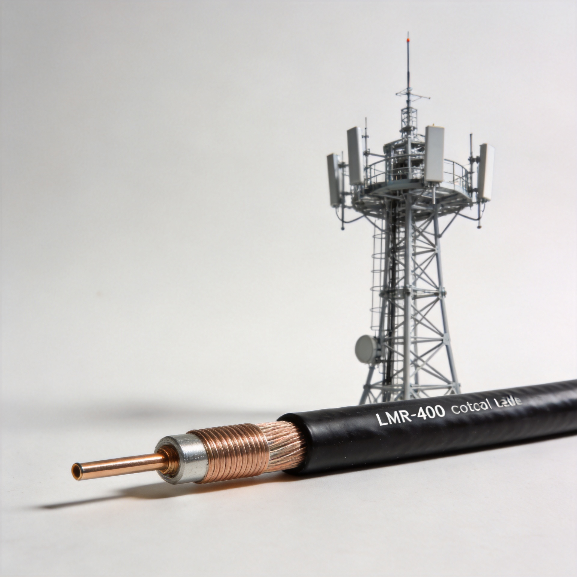
Half-inch coaxial cable delivers significantly lower insertion loss per meter, which is relevant when the harness cable spans more than the standard 1-3 meter connection range. In macro base station configurations with longer equipment-to-port runs, 1/2" cable assemblies reduce the cumulative signal budget penalty across the RF chain. For longer runs where loss budget matters, the Factory Price 1/2 Super Flexible Cable Assembly 4.3-10 Male To 4.3-10 Male Jumper combines 4.3-10 interface compatibility with lower per-meter loss. Where a 4.3-10 to N-type interface is required, the LMR600 Coaxial Cable Jumper Cable 4.3-10 Male To N Male LMR600 Cable Assembly provides a proven low-loss cable assy option for mixed connector environments.
PIM Performance Requirements
Passive intermodulation is generated at non-linear junctions: connector contact surfaces, cable terminations, and mechanical transition points. In 5G multi-band deployments—where a single radio unit operates simultaneously across 700 MHz, 1800 MHz, 2100 MHz, and 3.5 GHz—there is no frequency headroom to absorb unexpected intermodulation products. The standard specification for cable assy components in 5G base station applications is -150 dBc or better at 2×43 dBm test conditions.
A cable harness assembly that meets the PIM specification on the test bench must maintain that performance after mechanical cycling: connector mating and de-mating, temperature cycling, and installation torque variation. When ordering, request assembled product test data for the specific connector-cable combination, not just the connector series data sheet.
Environmental Protection: IP Ratings
Outdoor base station installations require connectors and cable assemblies rated for sustained environmental exposure. The relevant IEC 60529 IP levels for harness cable applications are:
- IP67: Dust-tight and protected against temporary water immersion to 1 meter for 30 minutes—suitable for sheltered outdoor installations.
- IP68: Dust-tight and rated for continuous water immersion—required for direct-exposure rooftop and mast cable harness assembly installations.
For 4.3-10 connectors, correct installation torque (typically 3.5–4.5 Nm) is required to engage the O-ring seal and maintain both the IP rating and PIM performance. Under-torqued connections compromise both simultaneously.
Matching Cable Assy to Installation Scenario
| Installation Scenario | Connector | Cable Type | Priority |
|---|---|---|---|
| Compact 5G small cell / AAU | 4.3-10 | 1/4" super flexible | Low PIM, connector footprint |
| Macro base station, short runs (<3m) | 4.3-10 or 7/16 DIN | 1/4" super flexible | Low PIM, ease of routing |
| Macro base station, longer runs (3m+) | 4.3-10 or 7/16 DIN | 1/2" low loss | Signal budget, loss per meter |
| Legacy site with 7/16 DIN interfaces | 7/16 DIN | Matched to run length | Interface compatibility |
| Outdoor rooftop / direct exposure | 4.3-10 (IP68) | Weather-rated harness cable | Environmental protection, PIM |
What to Confirm Before Ordering
Before committing to a cable harness assembly supplier for a 5G deployment, confirm:
- PIM test data for the assembled cable assy—connector series specification alone does not certify the assembled product. Request test results for the specific connector-cable combination.
- Custom length availability—standard catalog lengths rarely match installation requirements. Custom cable harness assembly production eliminates excess cable coil and reduces connector interface stress from forced routing.
- Batch consistency documentation—batch-to-batch variation in dielectric properties is a known procurement risk. Request test data spanning multiple production batches.
- IP rating for the assembled harness cable—confirm that cable entry and termination maintain the rated ingress protection for the deployment environment.
With 25 years of focused manufacturing experience in RF interconnect components, Zhenjiang Jiewei provides the low-PIM assembly testing, technical documentation, and custom cable assy production capability that 5G deployment projects require.
Conclusion
Selecting the right harness cable assembly for a 5G base station is systematic. Establish the connector interface from site compatibility and PIM requirements, determine the cable type from installation geometry and run length, confirm IP protection for the deployment environment, and validate PIM performance at the assembled cable assy level—not just at the connector. The RF jumper cable assemblies that perform reliably in the field are the ones specified correctly before installation begins.