EN

Active vs Passive DAS: Key Differences for Indoor Coverage
Choosing an active distributed antenna system or a passive DAS is not simply a question of which architecture is newer. It is a decision about how a building receives, transports, and radiates RF energy—and where the project can tolerate loss, complexity, and future change. For an office, venue, hospital, campus, or transport hub, the appropriate approach begins with the coverage objective rather than a preferred bill of materials.
As a network architect reviewing indoor systems, I start with the complete signal path: source, transport, distribution, antennas, feeders, connectors, and the access conditions for maintenance. An active distributed antenna system can be a strong fit when the footprint, band plan, or capacity target makes long RF runs difficult to manage. A passive design can be the more practical answer when the coverage area is contained and a disciplined RF loss budget is realistic.
What Changes Between Active and Passive DAS?
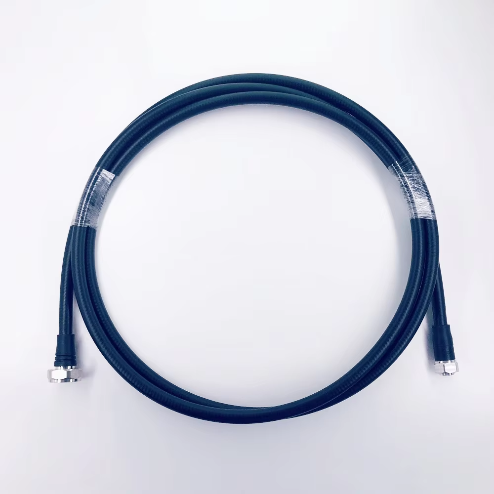
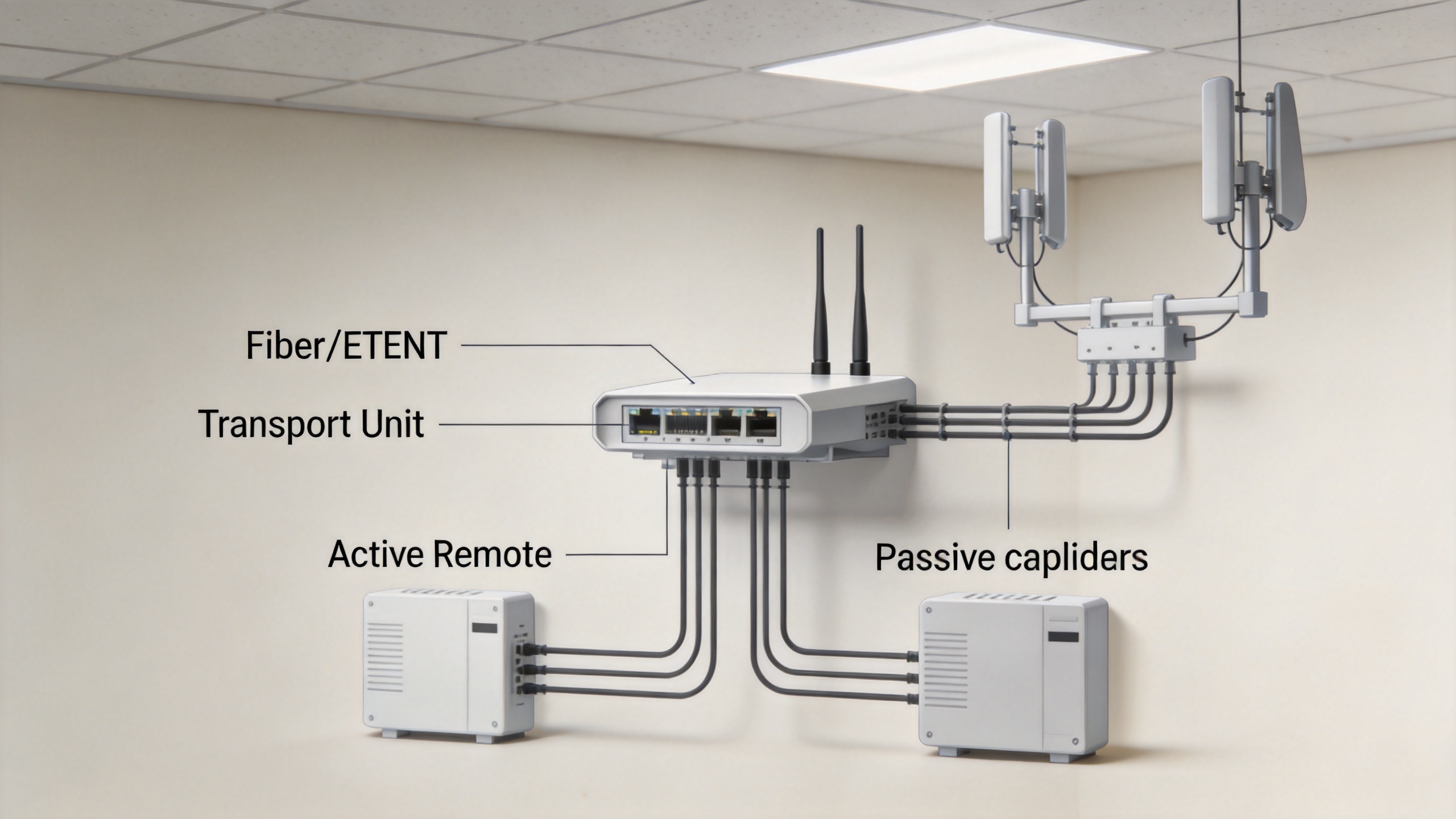
A passive DAS distributes RF using passive components such as coaxial feeder cable, splitters, taps, couplers, connectors, and indoor antennas. The incoming signal remains RF through the distribution network. That keeps the architecture familiar, but each cable run and passive device contributes insertion loss. In other words, the passive network must be designed around a credible power budget from the beginning.
An active distributed antenna system typically moves the source signal to remote units over fiber or Ethernet, then creates or converts the RF signal nearer to the antennas. This reduces the dependence on very long coaxial distribution runs. It also introduces powered equipment, active nodes, monitoring needs, and a more deliberate commissioning process.
| Decision factor | Passive DAS | Active DAS |
|---|---|---|
| Distribution path | RF over coaxial cable and passive devices | Signal transport to powered remote units, then local RF distribution |
| Primary design pressure | Feeder and passive-device loss budget | Remote-unit placement, power, transport, and system integration |
| Typical fit | Smaller or simpler indoor footprints with manageable cable runs | Larger, multi-zone, or capacity-sensitive indoor environments |
| Operations focus | RF path integrity and physical installation quality | RF performance plus powered-node and transport management |
Why the RF Loss Budget Matters More in Passive Design
The passive option is not a low-effort option. It substitutes active electronics with a carefully controlled RF path. Cable attenuation rises with frequency and length, while splitters, taps, connectors, and antennas add their own losses or interface constraints. A passive layout that looks neat on a floor plan can still disappoint if the farthest antenna branch has too little margin after every component is counted.
This is where the phrase “use the lowest-loss cable” can mislead. Cable loss matters, but so do impedance consistency, connector interfaces, bend radius, routing, termination practice, and inspection access. An active distributed antenna system shifts part of this challenge toward powered remotes, yet it does not remove RF discipline at the final antenna connections.
For both architectures, request the operating bands, antenna count, branch topology, expected cable lengths, connector types, and acceptance-test method before finalizing components. That creates a usable comparison instead of a generic equipment list.
When an Active Distributed Antenna System Is Usually Worth the Complexity
An active distributed antenna system deserves close consideration when the building has multiple floors, long horizontal distances, dense user areas, multiple frequency bands, or a coverage objective that cannot leave much room for feeder loss. It can also be appropriate when future changes are likely, because centralized transport and distributed remotes may offer a clearer way to extend zones than repeatedly redesigning long coaxial branches.
The trade-off is operational: active nodes need power, transport connectivity, placement coordination, and access for maintenance. If those building services are difficult to obtain, the engineering advantages of an active distributed antenna system should be weighed against installation constraints early, not after the RF design is complete.
When Passive DAS Remains a Sensible Choice
Passive DAS is often a sensible choice for compact facilities with predictable coverage zones, available source power, and cable paths short enough to preserve the link budget. Its distribution hardware is straightforward, and there are fewer powered field elements to support. That does not mean every small building should default to passive. Thick construction materials, unusual geometry, high-band operation, or strict performance expectations can make a conventional passive topology less forgiving.
A useful question is: can the team document the worst-case branch and still retain acceptable margin after installation realities are included? If the answer is uncertain, compare a passive design with an active distributed antenna system before committing to cable routes and ceiling work.
Component Checks That Support Either Architecture
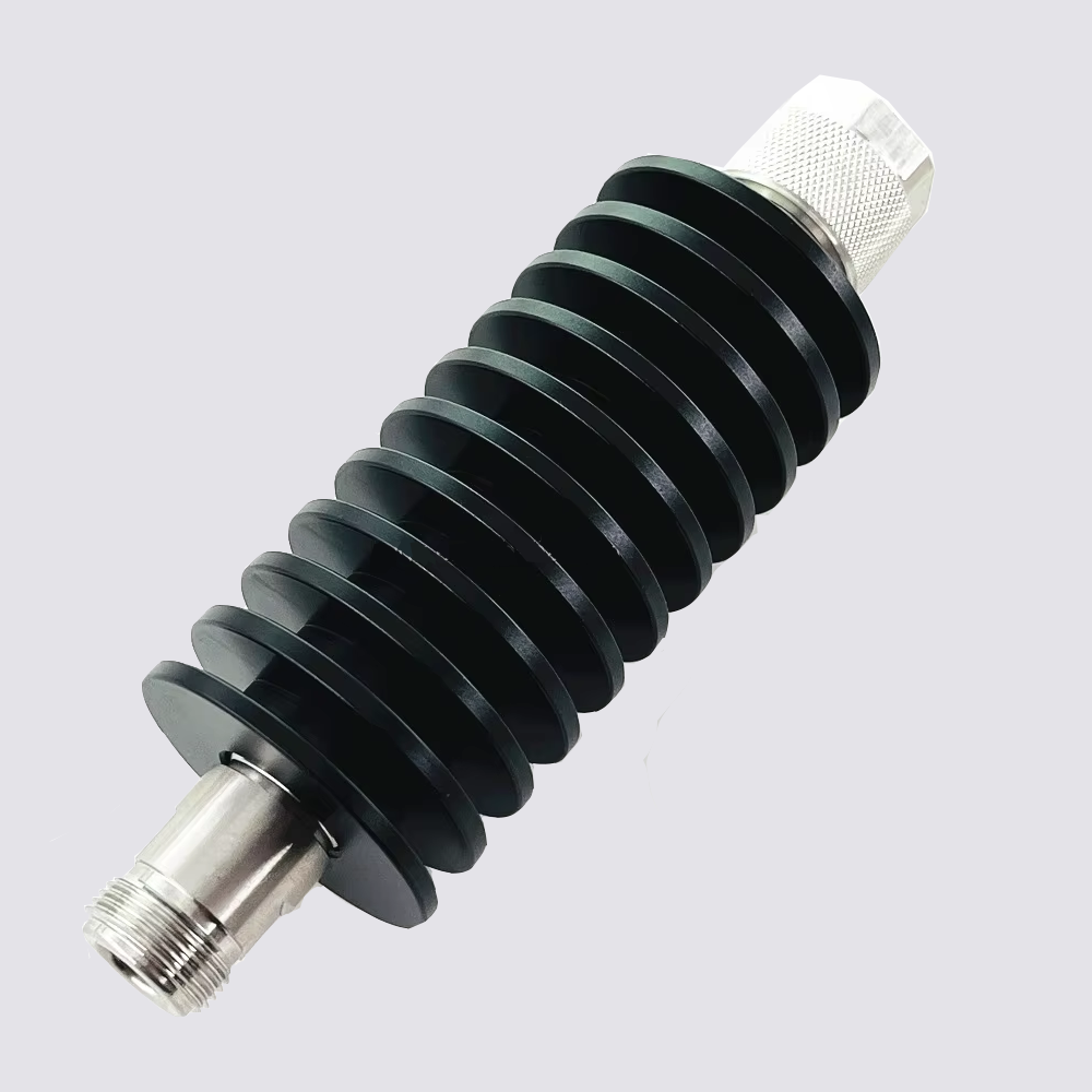
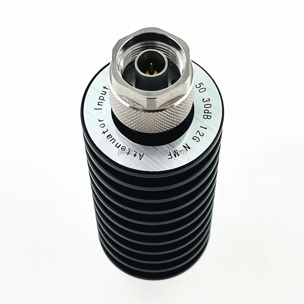
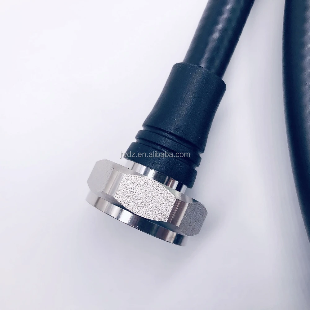
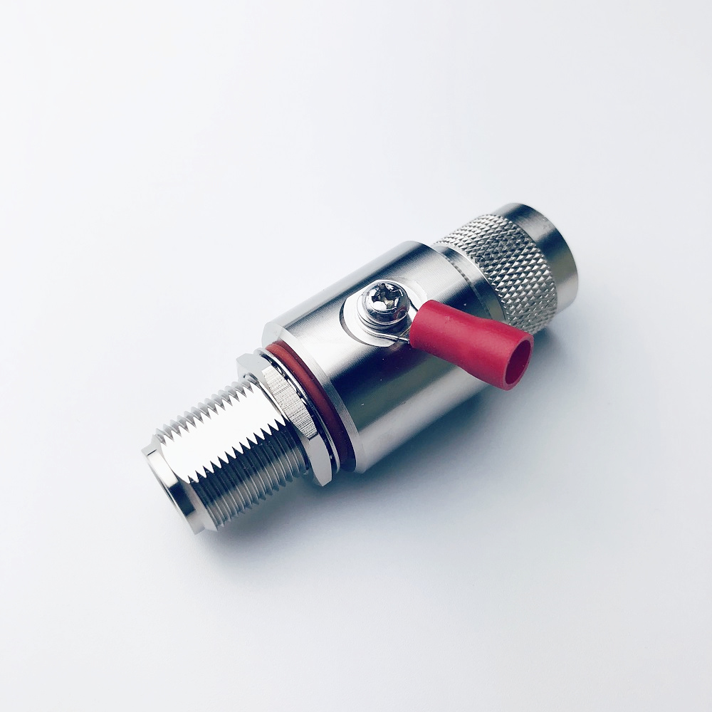
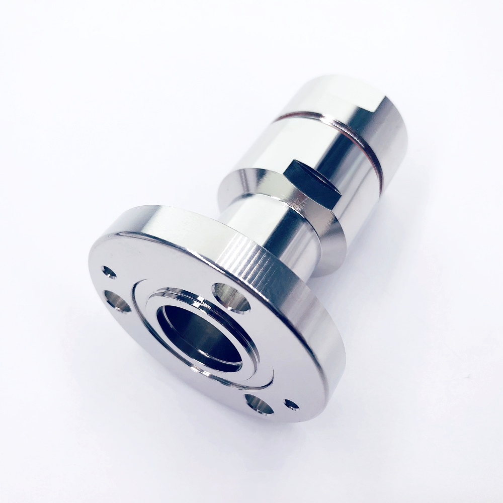
The active-versus-passive decision does not eliminate the need for compatible RF components. Antennas, feeder cables, jumpers, connectors, splitters, and terminations should be specified as one path, not purchased as isolated line items. Confirm frequency coverage, impedance, insertion-loss information, return-loss or VSWR requirements, connector mating interfaces, environmental exposure, and installation constraints.
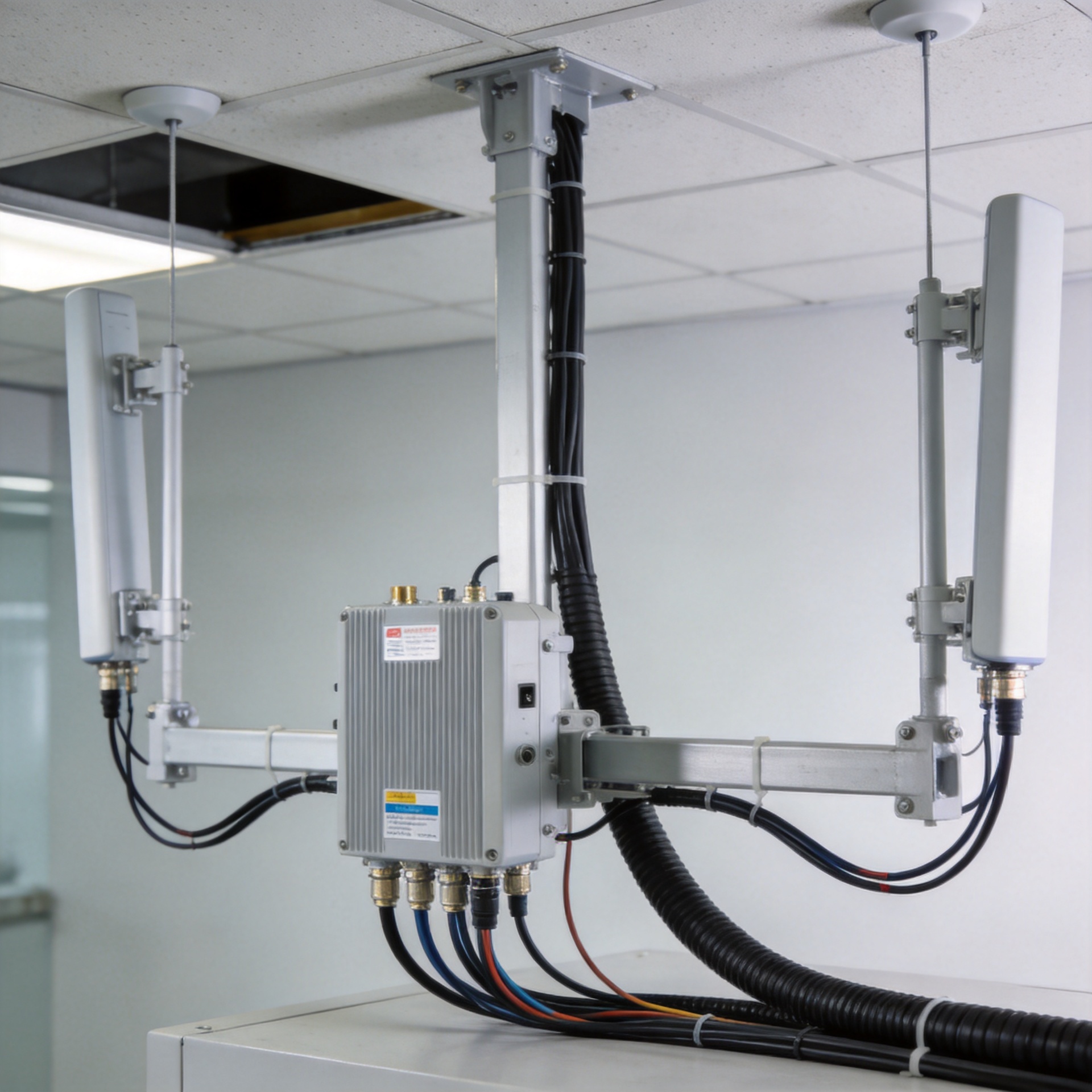
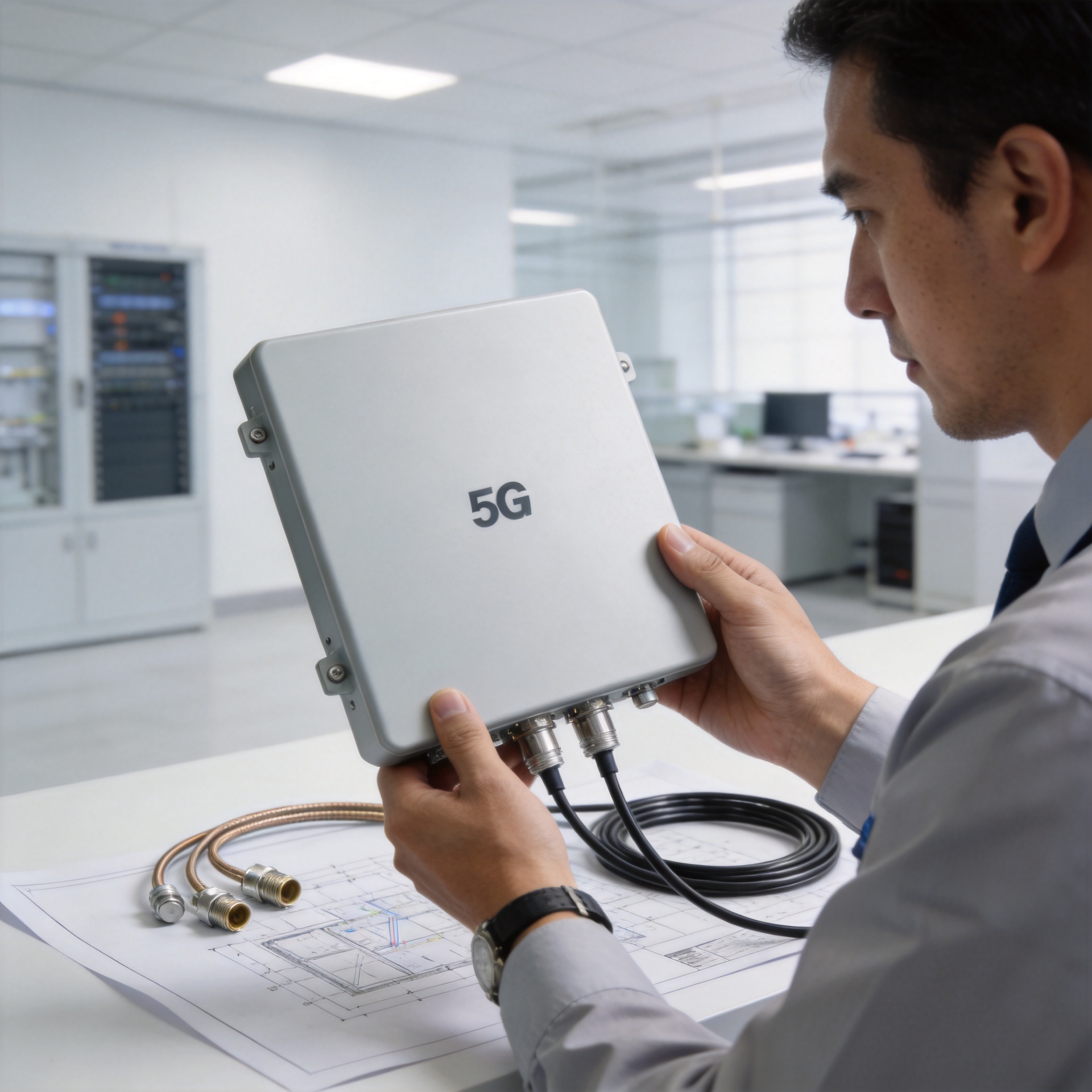
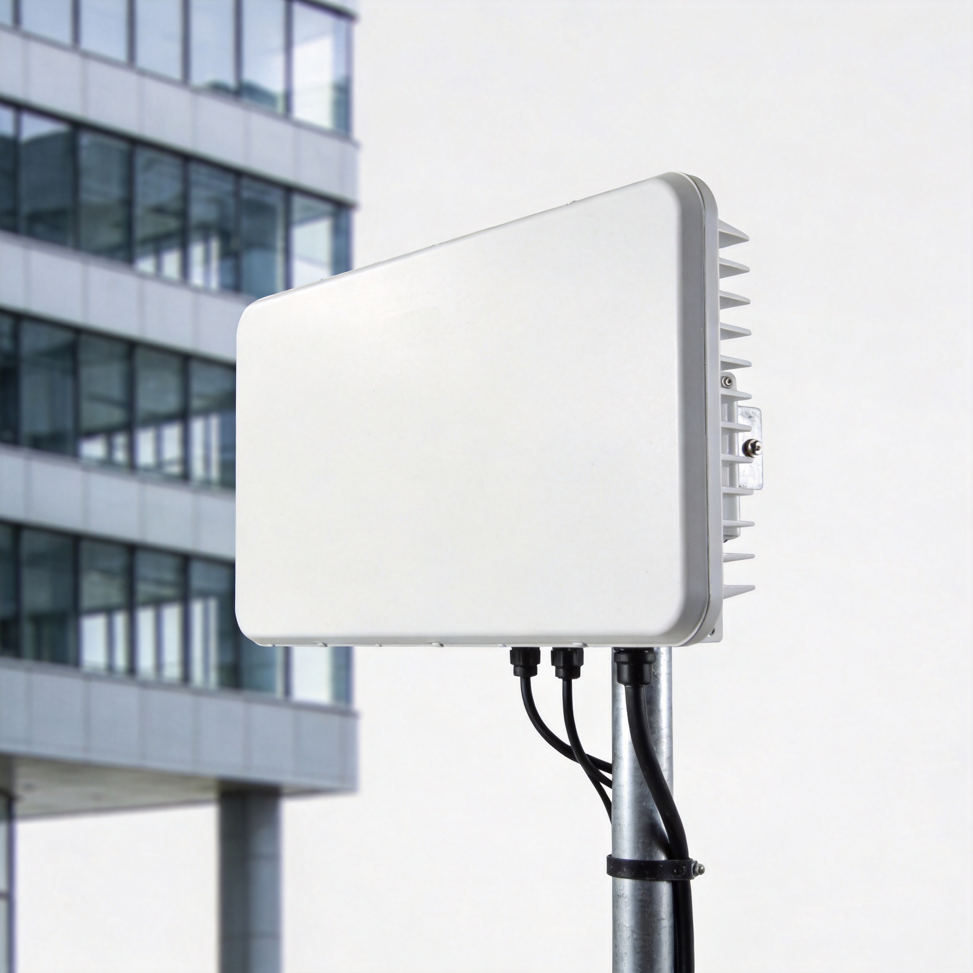
For a DAS-oriented antenna option, review the supplied product information and application compatibility rather than inferring performance from its name. The 5G 698–3800 MHz RF antenna for IBS DAS can be considered alongside the site’s actual band plan, mounting arrangement, and RF-path requirements.
It is tempting to treat the antenna as the final decision. It is not, quite. The antenna can only radiate the signal that arrives at its port, so the installed feeder and connector path must be evaluated with the same care.
A Practical Selection Sequence
- Define the service target. Identify the indoor areas, bands, carriers or signal source, traffic profile, and coverage acceptance criteria.
- Map the physical constraints. Review risers, cable lengths, telecom rooms, power availability, transport routes, ceiling access, and firestopping requirements.
- Model the passive path. Calculate the longest branch with all feeder, splitter, tap, jumper, connector, and antenna contributions included.
- Compare active transport. For challenging zones, evaluate whether an active distributed antenna system provides a more manageable path to remote antennas.
- Validate the bill of materials as a system. Match frequency, impedance, interface, mechanical installation, and test requirements across every item.
- Plan verification. Define post-install testing, labeling, documentation, and maintenance access before purchasing.
Final Takeaway
Neither architecture is automatically better. Passive DAS favors a simpler distribution chain where cable loss and layout remain controllable. An active distributed antenna system is often better aligned with larger, more complex, or more demanding indoor coverage scenarios, provided that power, transport, and lifecycle support are part of the plan. Make the choice from the system requirements outward, then qualify the RF components that make that design repeatable in the field.