EN

5G Panel Antenna Specifications to Review Before Deployment
A 5g panel antenna can look straightforward on a quotation: a frequency range, a gain figure, a connector, and a mounting bracket. In a DAS or indoor-coverage project, however, those fields only work when they match the radio, feeder path, coverage objective, and installation environment as a system. A mismatch may not show up until commissioning, when correcting it is far more disruptive than checking it during design.
For procurement, RF engineering, and installation teams, the practical question is not “Does this 5g panel meet one headline specification?” It is “Can this antenna support the planned bands and coverage geometry without creating a weak interface elsewhere in the RF path?” The following checklist is designed for that consideration-stage decision.
1. Start with the operating-band plan, not the word “5G”
The first specification to verify is the usable frequency range. 5G does not describe one universal frequency band, and many indoor systems also need legacy cellular bands in the same coverage layer. Compare the antenna’s rated range against the operator bands, DAS architecture, and any planned expansion bands—not just against the highest frequency in a brochure.
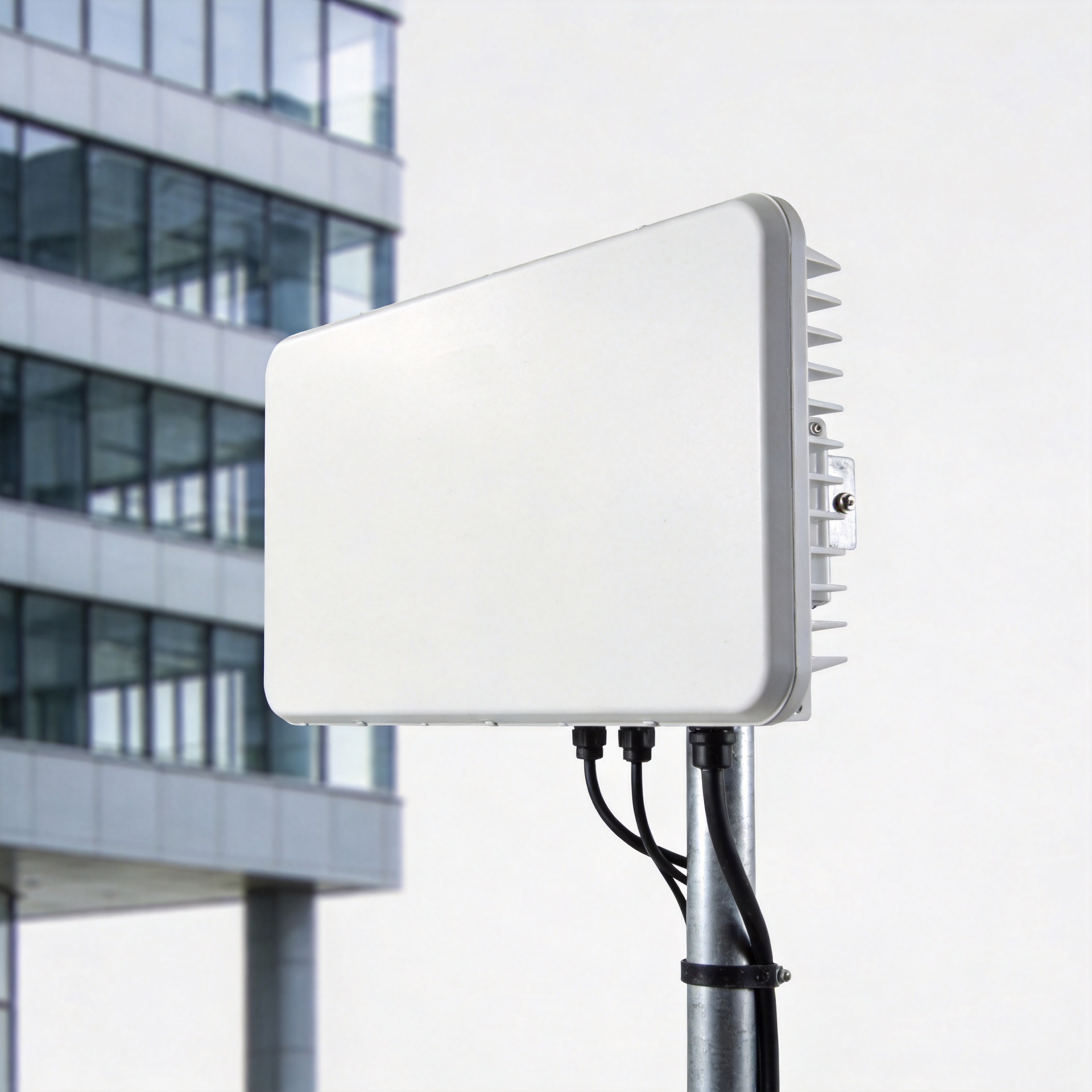
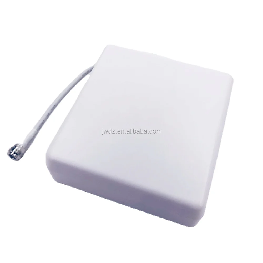
For example, the 5G 698-3800 MHz RF Antenna High Gain Outdoor Panel Antenna 7-8dBi Outdoor Panel Directional Antenna Widely for IBS DAS is published for 698–3800 MHz coverage. That range can be relevant for a sub-6 GHz multi-band deployment, but it still needs to be checked band by band against the project design. Treat the frequency range as a pass/fail gate before comparing gain or price.
- List every uplink and downlink band the system must carry.
- Confirm the antenna specification covers the required bands with stated performance, not merely a nominal label.
- Check whether the deployment requires one broad-band antenna or separate antennas for different coverage zones.
2. Match gain and beamwidth to the coverage geometry
Gain is useful only in context. A higher-gain 5g panel usually concentrates energy into a narrower pattern; that can improve reach in a corridor, aisle, façade, or targeted sector, but it can also leave adjacent areas under-served if the beam is too narrow. Review horizontal and vertical beamwidth alongside gain, installation height, downtilt, and the distance to the intended coverage area.
Published directional DAS examples show that models within a similar 698–3800 MHz category can have materially different gain options. The matched product is listed at 7–8 dBi, which is a product-specific value rather than a universal target. Ask for radiation-pattern data at the bands that matter most, then check the design prediction against real obstructions such as walls, metalwork, racks, glazing, and cable trays.
| Specification | What to compare | Deployment consequence |
|---|---|---|
| Gain | Value by frequency band | Changes reach and signal concentration. |
| Horizontal beamwidth | Target zone width and azimuth | Determines whether the panel covers the intended sector. |
| Vertical beamwidth | Mounting height, tilt, and floor geometry | Helps avoid overshooting or creating a near-field gap. |
| Front-to-back behavior | Nearby cells and rear-facing spaces | Supports interference and isolation planning. |
3. Verify polarization, port count, and MIMO mapping together
Polarization is not a box to tick independently from ports. Confirm whether the 5g panel is single-polarized, dual-polarized, or designed for a specific MIMO arrangement. Then map every antenna port to the radio or DAS output, including the required polarization orientation and any port labeling convention. A dual-polarized panel is only useful when its ports are connected and oriented as the RF design intends.
This is especially important when the procurement team is standardizing components across sites. Standardization can simplify spares, and that logic is sound. The problem is that it only holds when the selected panel has the required port configuration across every band and coverage scenario. Put the port map in the submittal package, not just in the installer’s memory.
- Confirm the number of RF ports required today and whether future MIMO expansion is planned.
- Check polarization type and orientation at each port.
- Request port-to-port isolation and cross-polarization information when system performance depends on it.
- Make sure port labels, jumper labels, and commissioning records use the same naming convention.
4. Treat impedance, VSWR, and connectors as an interface chain
A 5g panel does not operate in isolation. Its impedance, return-loss behavior, connector interface, jumper assembly, and feeder cable must work together. A nominal 50-ohm system still needs compatible connector types, proper torque practices, suitable cable assemblies, and an RF acceptance process. The antenna connector may be correct while the assembled path introduces the loss or reflection that compromises commissioning.
Review the VSWR or return-loss specification across the bands you will use, then define what will be verified after installation. The specification that appears most reassuring on a room-temperature datasheet can be affected by mechanical strain, moisture ingress, or thermal cycling in an actual deployment. That is why an incoming-goods check and a post-install sweep are operational controls, not unnecessary paperwork.
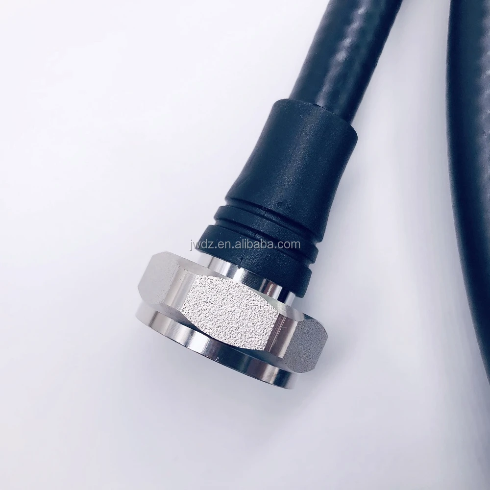
- Confirm the connector series, gender, and interface standard at both antenna and feeder ends.
- Match jumper length and cable type to the loss budget; do not substitute cable material without RF verification.
- Specify inspection, torque, weatherproofing, and test records for every critical connection.
- Define the acceptance measurement: frequency range, test port, and allowable result.
5. Check mounting, environmental exposure, and maintainability
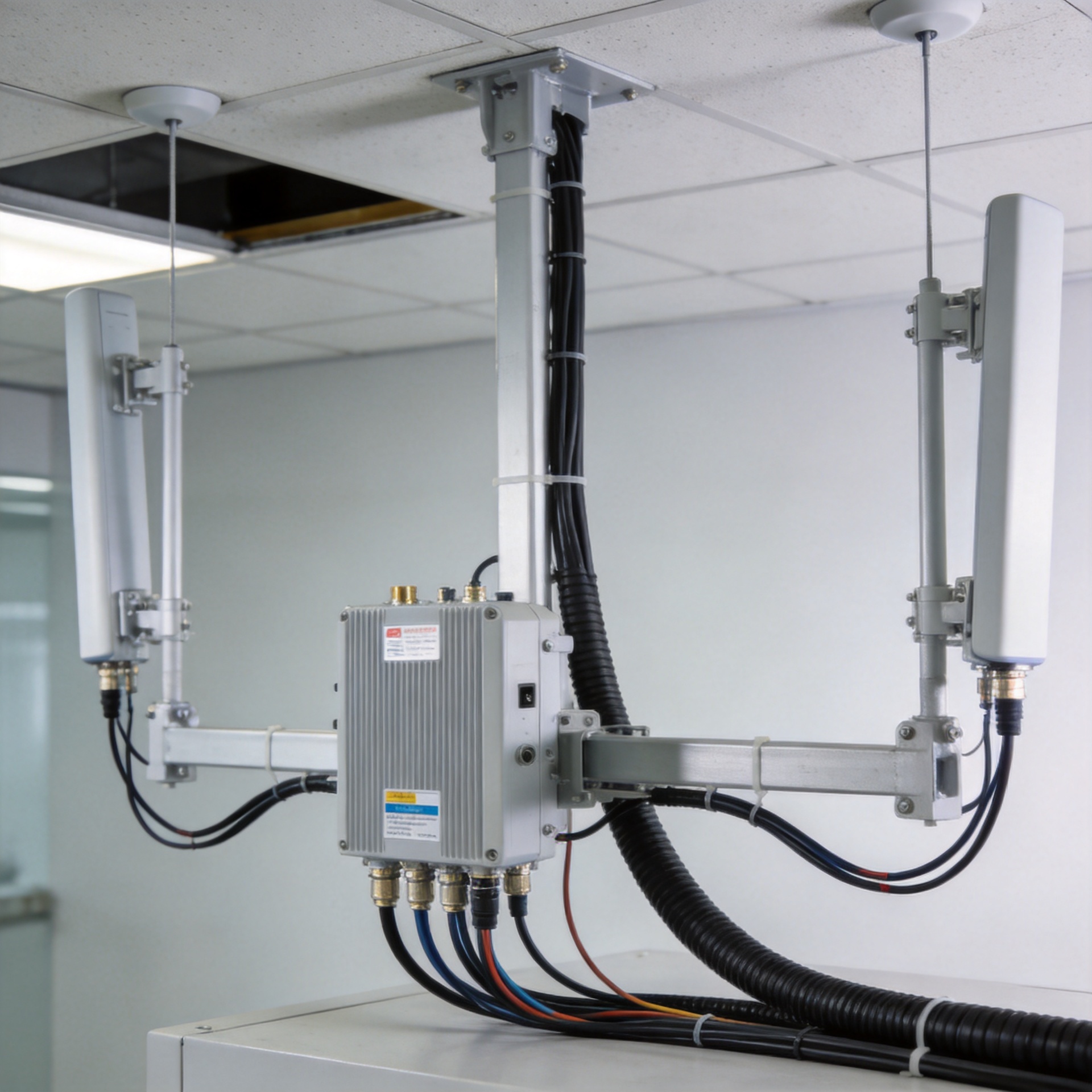
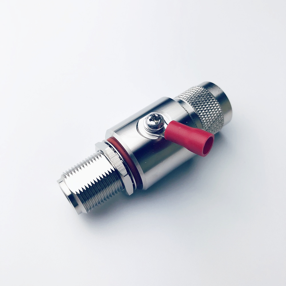
So that covers the electrical side. Now comes the mechanical interface—the part that often determines whether an approved specification remains reliable after installation. Confirm wall, pole, ceiling, or bracket compatibility; mast diameter limits; azimuth and downtilt adjustment; cable exit direction; antenna weight; and clearance for weatherproofed connectors.
For outdoor or semi-outdoor coverage, confirm the enclosure rating, operating-temperature range, wind-loading assumptions, corrosion exposure, and grounding approach. For indoor DAS, assess fire and building requirements, access for service, and whether the panel location changes the beam path after partitions or fixtures are installed. Do not assume a supplied bracket solves every site-specific mounting constraint.
6. Use a cross-functional pre-deployment checklist
Infrastructure telecom purchases are rarely decided by one person: RF engineers establish performance requirements, procurement qualifies the supplier, installers handle the physical interface, and operations inherits the maintenance burden. A short joint review before release reduces avoidable rework.
- RF engineering: approve bands, gain, beamwidth, polarization, ports, impedance, and acceptance limits.
- Procurement: confirm that the quoted model, connector configuration, and documentation exactly match the approved sample and BOM.
- Installation: validate mounting hardware, cable routes, bend radius, weatherproofing, grounding, and access.
- Commissioning: record port mapping and test the installed RF path against the agreed criteria.
- Operations: retain model, serial/batch, mounting, and test records for troubleshooting and future expansion.
5G Panel Specification Sign-Off Matrix
Use this sign-off matrix to ensure every 5g panel requirement is owned, documented, and verified before release. The repeated 5g panel checkpoints below are intentionally specific: each one converts a broad datasheet field into an action for the appropriate project owner.
| 5g panel checkpoint | 5g panel sign-off question |
|---|---|
| 5g panel frequency range | Does the 5g panel cover every approved operating band? |
| 5g panel gain | Is the 5g panel gain validated at the design frequencies? |
| 5g panel horizontal beamwidth | Does the 5g panel azimuth pattern suit the target zone? |
| 5g panel vertical beamwidth | Does the 5g panel elevation pattern suit height and tilt? |
| 5g panel polarization | Is the 5g panel polarization mapped to every radio port? |
| 5g panel port count | Does the 5g panel port count support the required MIMO scheme? |
| 5g panel isolation | Is 5g panel isolation sufficient for the intended configuration? |
| 5g panel impedance | Does the 5g panel match the planned 50-ohm RF path? |
| 5g panel VSWR | Is the 5g panel return-loss limit included in acceptance testing? |
| 5g panel connector | Does the 5g panel connector match the approved jumper interface? |
| 5g panel grounding | Is the 5g panel grounding approach defined in the method statement? |
| 5g panel weatherproofing | Will the 5g panel interfaces be sealed after testing? |
| 5g panel batch record | Is the 5g panel batch traceable to the approved submittal? |
| 5g panel sweep test | Will the 5g panel installed path be RF-tested at handover? |
| 5g panel service access | Can the 5g panel be safely inspected or replaced later? |
Make the specification review part of deployment control
A cost-effective 5g panel decision should consider more than the unit price. Installation labor, replacement access, RF rework, and delayed commissioning all belong in the cost equation. A specification checklist turns those downstream risks into questions that can be answered before the antenna reaches the site.
For DAS and indoor-coverage sourcing, begin with the actual band plan, then verify coverage pattern, polarization and ports, RF interfaces, and mounting conditions as one connected decision. When a project needs a published 698–3800 MHz directional panel option for IBS DAS evaluation, the linked product page can be reviewed alongside the complete project RF design and installation requirements.