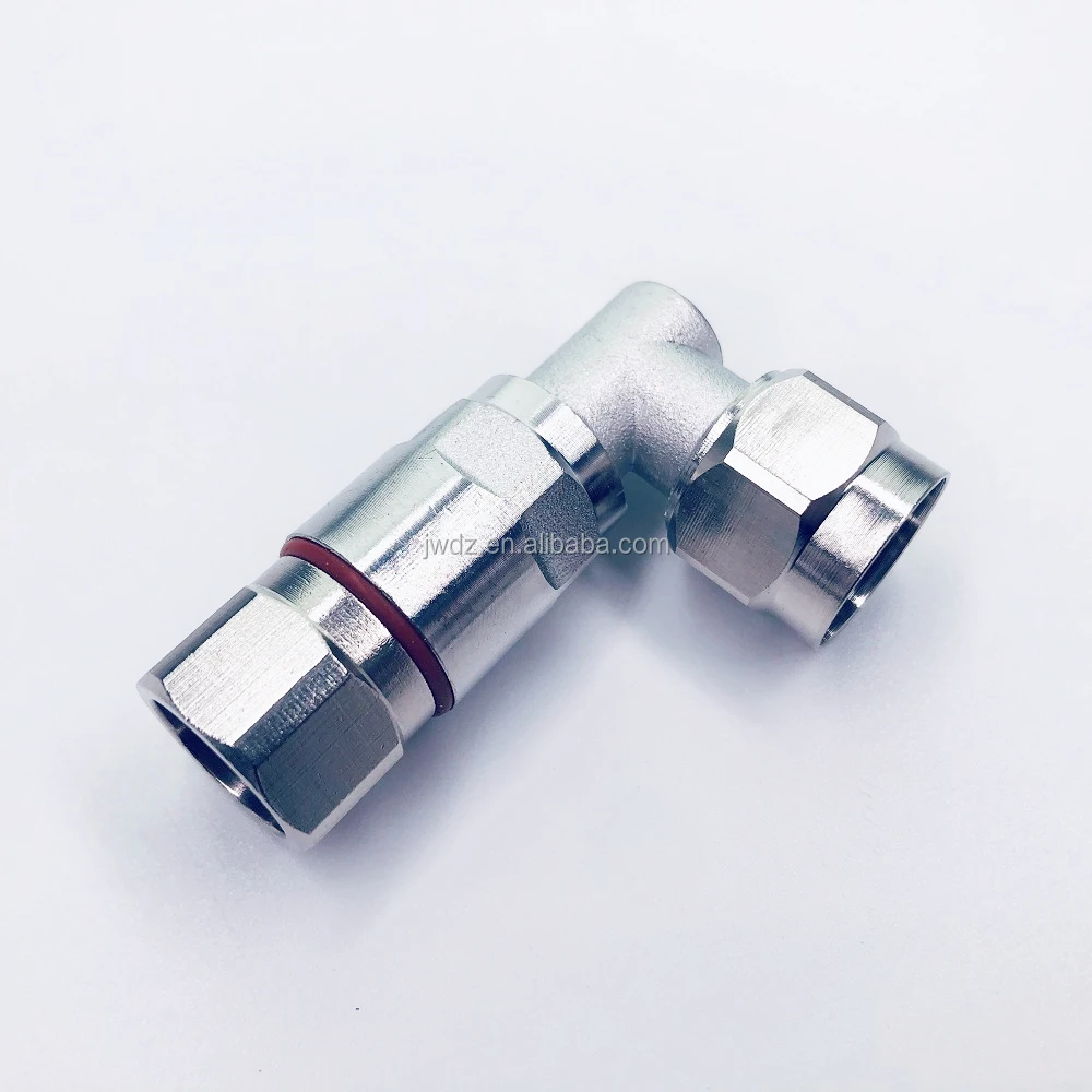
Koaxiální kabely s vzduchovou dielektrikou dosahují vynikajícího výkonu ve vysokofrekvenčních (RF) systémech díky specializovanému inženýrskému řešení. Na rozdíl od běžných konstrukcí s pevným dielektrikem tyto kabely nahrazují souvislou izolaci přesně umístěnými rozpěrkami, které udržují vodivé části oddělené vzduchem – nejmenší možnou ztrátovou dielektrickou vrstvou dostupnou.
Duté vzduchové dielektrické struktury snižují srážky elektronů při průchodu signálů, což znamená menší spotřebu energie na cestě. Vzduch má dielektrickou konstantu blízkou hodnotě 1,0, zatímco materiály jako polyethylen mají hodnotu kolem 2,3 nebo vyšší. Kvůli tomuto rozdílu způsobuje vzduch mnohem menší fázové zkreslení a v systému se hromadí nižší kapacita. Průmyslové testy ukazují, že tyto konstrukce plné vzduchu vykazují přibližně o 40 % nižší útlum signálu na frekvenci 6 GHz ve srovnání s tradičními alternativami z pěnového PE, jak vyplývá z nedávných studií RF materiálů z minulého roku. Pro inženýry pracující s vysokofrekvenčními systémy je to velmi důležité, protože malé ztráty mohou postupem času výrazně negativně ovlivnit celkový výkon.
Kabely se vzduchovým dielektrikem a s pevným polyethylenem (PE) vykazují zásadní rozdíly ovlivňující RF výkon:
| Charakteristika | Vzduchové dielektrikum | Pevné dielektrikum z PE |
|---|---|---|
| Dielektrický materiál | Vzduchové mezery s plastovými rozpěrkami | Spojitá pěna z polyethylenu |
| Útlum (6 GHz) | ~0,15 dB/m | ~0,25 dB/m |
| Stabilita fáze | Vyšší (nižší dielektrická konstanta) | Střední variabilita |
Mechanická tuhost konstrukcí s vzduchovým dielektrikem zabraňuje deformaci dielektrika při ohybu, čímž se udržuje stálá impedance. Naproti tomu jsou kabely s polyethylénovou izolací náchylnější ke změnám kapacity způsobeným stlačením – což zvyšuje poměr stojatého vlnění napětí (VSWR).
Koaxiální kabel s vzduchovou dielektrikou opravdu vyniká udržením kvality signálu ve vysokých frekvenčních pásmech díky svému vzduchovému jádru, které snižuje ztráty signálu. Podle standardního testování dle IEC 61196 vykazují tyto kabely útlum kolem 0,15 dB na metr při frekvenci 6 GHz, což je téměř polovina hodnoty u běžných kabelů s pevným polyethylénovým dielektrikem. Čím jsou tak efektivní? V podstatě ztrácejí méně energie prostřednictvím izolačního materiálu, což znamená, že signály mohou urazit mnohem delší vzdálenosti, než než je nutné je zesílit. Pro odborníky zabývající se RF technikou to znamená méně potíží se zeslabováním signálu na dálku a potenciální úspory na nákladech za dodatečná zařízení.
| Frekvenční pásmo | Útlum vzduchové dielektriky (dB/m) | Útlum pevného PE dielektrika (dB/m) |
|---|---|---|
| 1 GHz | 0.03 | 0.07 |
| 3 GHz | 0.08 | 0.18 |
| 6 GHz | 0.15 | 0.29 |
Systémy využívající tuto technologii dosahují účinnosti přenosu energie 96 % u 5G zálohovaných spojů (IEEE 2023), čímž snižují energetické náklady o 740 tisíc USD ročně na každé nasazení 1 000 uzlů.
Dutý design umožňuje bezkonkurenční tepelný výkon. Kabely s vzduchovou dielektrikou zvládnou kontinuální výkon 5 kW při okolní teplotě 40 °C – dvojnásobnou kapacitu ve srovnání s alternativami na bázi pěny. Mezi klíčové výhody patří:
Tato tepelná odolnost zabraňuje posunům impedance během přenosu vysokého výkonu, čímž snižuje VSWR na hodnotu 1,05:1 u radarových systémů s frekvencí 6 GHz. Terénní testy ukázaly dostupnost 99,8 % u vysílacích zařízení po 15 000 provozních hodinách.
Při porovnání koaxiálních kabelů s vzduchovou dielektrikou s jejich kolegy s pěnovou dielektrikou, jako jsou typy LMR® nebo LDF/AL4, vynikají tři hlavní faktory, které jsou rozhodující pro RF systémy: útlum signálu na délce vedení (vložný útlum), poměr stojatého vlnění napětí (VSWR) a odolnost vůči prostředním vlivům. Kabely s vzduchovou dielektrikou ztrácejí přibližně o 20 až 30 procent méně signálu nad frekvencí 2 GHz, protože absorbují méně dielektrického materiálu, což je činí ideálními pro dlouhé spoje na vysílačské věže a rozprostřené anténní systémy. Ale existuje jedna nevýhoda. Kabely s pěnovou dielektrikou ve skutečnosti lépe zvládají stabilitu fázových charakteristik a odolnost proti hromadění vlhkosti, což je zásadní v mokrých venkovních podmínkách, kde mohou kabely se vzduchovou dielektrikou trpět vnitřním orosením. Hodnoty VSWR ukazují další obrázek. Přímé úseky kabelů se vzduchovou dielektrikou udržují poměrně dobré hodnoty kolem 1,15:1, ale při příliš těsném ohýbání se impedance začne měnit nad 1,25:1. Pěnové kabely zůstávají pod hodnotou 1,2:1 i při složitých trasách instalace. Pokud jde o celkovou spolehlivost systému, nabízejí pěnové varianty lepší rovnováhu, i když mají mírně vyšší ztráty signálu. Poskytují konzistentnější stínění a mnohem lépe odolávají tlakovým silám než kabely se vzduchovou dielektrikou, které jsou známé svou tuhostí a mohou značně ztěžovat instalaci v určitých situacích.
Kabely s vzduchovou dielektrikou nabízejí lepší integritu RF signálu díky nižší ztrátě signálu a vyšší fázové stabilitě, což je důsledkem jejich konstrukce se vzduchovým jádrem.
Kabely s vzduchovou dielektrikou mají nižší dielektrickou konstantu a kapacitu, čímž se minimalizuje fázová zkreslení a útlum při vysokofrekvenčních aplikacích.
Kabely s vzduchovou dielektrikou nabízejí nižší ztrátu signálu, ale jsou méně odolné proti vlhkosti a mohou být kvůli tuhosti náročnější na instalaci.
 Aktuální novinky
Copyright © 2024 Zhenjiang Jiewei Electronic Technology Co., Ltd. - Zásady ochrany osobních údajů