EN
EN

How Fixed RF Attenuators Work in Communication Systems
An rf fixed attenuator is a passive component that reduces RF signal power by a known amount. In a communication system, it gives engineers a simple, repeatable way to set a signal level without changing the signal path architecture. Whether the goal is protecting a sensitive receiver, creating a realistic test condition, or improving the interaction between stages, an rf fixed attenuator makes the reduction predictable in decibels.
For RF engineers, the important point is that attenuation is not merely “making a signal smaller.” A properly selected rf fixed attenuator is designed to work with a characteristic impedance—commonly 50 ohms—and to preserve a stable interface between the equipment on either side. That is why it is a familiar building block in telecom equipment, broadcast chains, lab fixtures, and antenna-related signal paths.
What Happens Inside an RF Fixed Attenuator?
At its core, an rf fixed attenuator uses a resistive network. The network converts a controlled portion of RF energy into heat while presenting the intended impedance at its input and output. Engineers specify the amount of reduction in dB: a 10 dB rf fixed attenuator lowers power by a factor of ten, while a 20 dB part lowers it by a factor of one hundred. The exact relationship depends on whether the measurement is expressed as power or voltage, so system documentation should state the reference clearly.
Unlike a variable attenuator, an rf fixed attenuator has one defined attenuation value. That fixed value makes it useful where repeatability matters more than adjustment. Once installed, it introduces the same nominal loss every time the system is operated within its rated frequency and power limits.
Why Communication Systems Need Controlled Signal Reduction
Transmitters, amplifiers, filters, mixers, receivers, and test instruments each have preferred operating ranges. If a stage receives too much power, it can compress, distort a measurement, or in the worst case exceed its input rating. Placing an rf fixed attenuator before that stage reduces the level in a controlled way. The component is passive, so it does not require bias power or control software.
An rf fixed attenuator can also make a test setup more representative of a real installation. For example, a bench connection may be much shorter and lower loss than a feeder path in service. Adding a known attenuator lets a technician simulate part of that loss and evaluate receiver margin, automatic gain control behavior, or signal-level alarms under repeatable conditions.
Impedance Continuity: A Second Job Beyond Loss
RF systems are sensitive to impedance discontinuities. A mismatch can reflect energy back toward the source, creating ripple, degraded return loss, and measurement uncertainty. Because an rf fixed attenuator is built around a specified impedance, it can provide isolation between imperfectly matched stages. It does not correct every mismatch or replace good system design, but a modest attenuation pad can reduce the impact that one stage has on another.
This is especially useful in test chains where a generator, adapter, cable assembly, and device under test may not all behave ideally across the same frequency span. An rf fixed attenuator placed at a strategic interface can improve measurement stability by reducing the magnitude of reflected signals that return to the source or analyzer.
Common RF Fixed Attenuator Applications
- Receiver protection: An rf fixed attenuator reduces a strong incoming signal before it reaches a receiver or measurement port.
- Level setting: Engineers use an rf fixed attenuator to establish a known drive level for an amplifier, mixer, or test fixture.
- Test repeatability: A known pad makes it easier to reproduce a setup across benches, teams, and service locations.
- Mismatch isolation: An rf fixed attenuator can lessen the practical effect of reflection interactions between cascaded devices.
- Signal-path simulation: A fixed loss element can represent part of the loss of a cable, feeder, or installed network.
Parameters to Check Before Selecting One
The attenuation value is only the starting point. Choose an rf fixed attenuator by checking its impedance, operating frequency range, power rating, connector interface, and environmental requirements. A unit that is suitable at low frequency may not maintain the required RF performance at a higher band. Likewise, a power rating must account for the energy that will be dissipated as heat, including possible high-power or fault conditions.
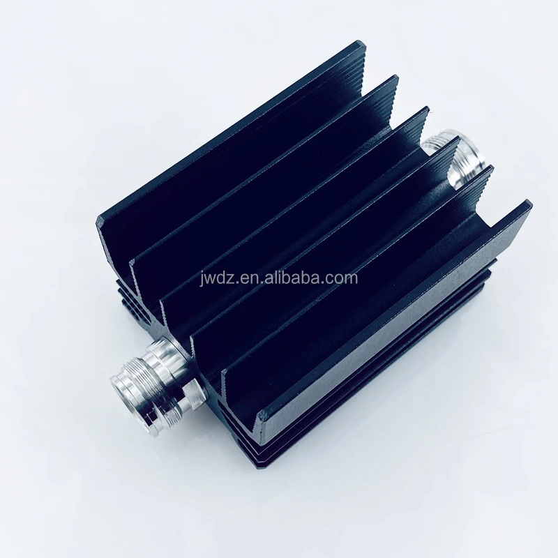
Connector compatibility matters too. Avoid treating adapters as an afterthought: every extra interface can add loss, reflections, and mechanical constraints. For applications that require a coaxial solution, review the confirmed product data and connector type before installation. One available option is this 100W 20dB.30dB.40dB.50dB 3GHz 4GHz 4.3/10 Attenuator; verify its published specifications against the actual system requirement.
A Practical Selection Workflow
- Define the signal level at the input and the safe target level at the next stage.
- Calculate the required dB reduction and confirm the tolerance that the application can accept.
- Match the rf fixed attenuator impedance to the system, typically 50 ohms in many communication applications.
- Check frequency coverage, power handling, connector gender, and mounting constraints.
- Validate the installed signal level and return-loss behavior with the appropriate RF test equipment.
Key Takeaway
An rf fixed attenuator is a precise passive tool for managing signal power while supporting a more controlled RF interface. It helps communication-system designers protect inputs, set repeatable levels, and reduce unwanted interaction between stages. By selecting the right attenuation value together with the correct impedance, frequency range, power rating, and connector format, engineers can make a small component deliver a meaningful improvement in system control.