EN

GDT Surge Protection for 5G Antenna Feed Lines
5G antenna systems place RF equipment closer to exposed rooftops, towers, and distributed radio locations. That makes gdt surge protection a practical part of feeder-line design rather than an afterthought. A gas discharge tube (GDT) can provide a low-capacitance path for high-energy surge current when it is integrated into a correctly selected, correctly grounded coaxial protector. The goal is not simply to add a protector; it is to preserve the RF path while creating a controlled route for surge energy away from radios, remote units, and monitoring equipment.
For a 5G feed line, the selection question is usually a system question: which interface, operating band, grounding method, and protection topology fit the installed antenna path? This article explains the checks that help RF engineers, procurement teams, and installation crews evaluate gdt surge protection without assuming that one protector suits every site.
Why gdt surge protection belongs in a 5G feeder-line plan
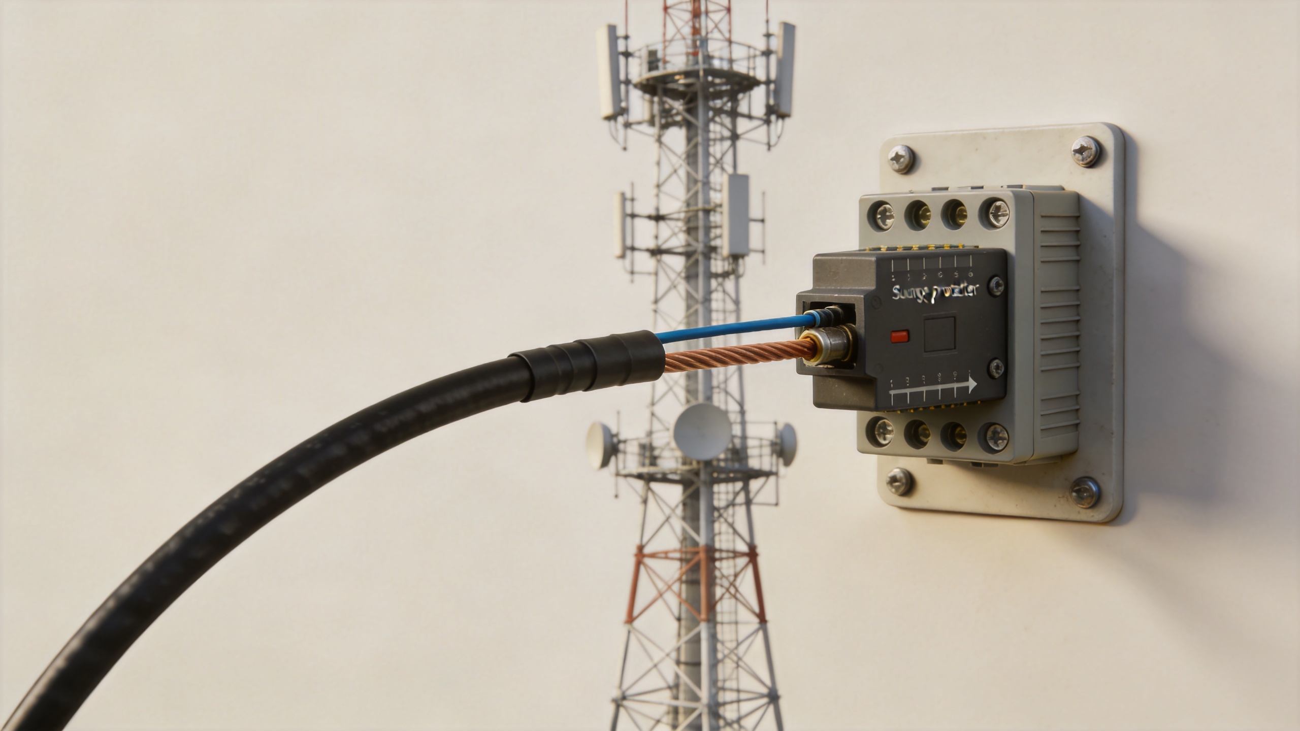
Outdoor antenna systems can be exposed to direct or nearby lightning events, induced transients, and potential differences between structures. Coaxial cable can carry that energy toward sensitive downstream equipment. In a suitable protector, the GDT changes from a high-resistance state to a conductive discharge path when its operating threshold is reached, directing surge energy toward ground. Its low off-state capacitance is especially useful in RF applications because unwanted capacitance can disturb a high-frequency signal path.
That does not mean a GDT alone guarantees protection. A complete gdt surge protection scheme also depends on bonding, grounding, equipment layout, cable routing, and the protection already present at the radio or building entry. A poor earth connection or a long, inductive ground lead can reduce the value of an otherwise appropriate coaxial protector.
Start with the protected RF path, not the surge rating alone
The first check is the actual feed-line path: its frequency range, impedance, connector family, power level, and whether DC or control signals share the route. 5G deployments may use different bands and interfaces across macro cells, small cells, DAS nodes, and test points. A protector that survives a surge but adds unacceptable insertion loss or return loss at the operating band is not a good system choice.
When reviewing gdt surge protection, ask for RF data across the working frequency range, including VSWR or return loss and insertion loss. Confirm that the protector is specified for the same nominal impedance as the cable system—typically 50 ohms in cellular feeder applications—and that connector genders and mechanical interfaces match the installation. Avoid solving a mismatch with unnecessary adapters, because every added interface can affect signal integrity and create another weatherproofing point.
Interface and frequency checks
- Verify the stated operating frequency range covers the actual 5G band or bands in use.
- Match the protector's impedance and connector interfaces to both sides of the feeder connection.
- Review insertion loss and VSWR or return-loss data at relevant frequencies, not only at a single low-frequency point.
- Confirm power handling against the site design and any applicable derating conditions.
- Check whether the installation requires weather sealing, environmental protection, or a specific mounting arrangement.
Choose the right protection topology for the feed line
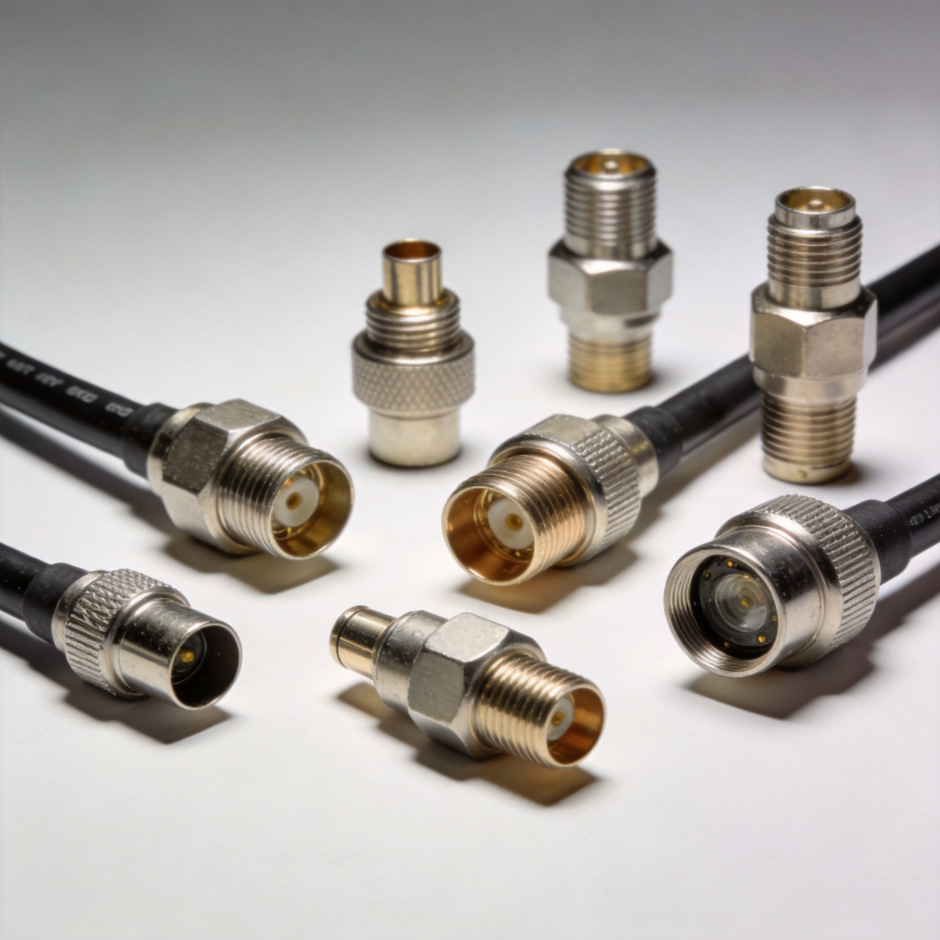
Coaxial lightning protectors use different approaches. A GDT-based design is often selected where strong surge-current handling and low capacitance are important. Some coaxial systems also use quarter-wave shorting protectors, which can present a short to surge energy while remaining tuned for a defined RF band. The appropriate choice depends on the operating frequencies, bandwidth requirements, whether the line carries DC, and the site grounding architecture.
For broadband or multi-band 5G antenna paths, verify that the topology supports the needed frequency coverage. For narrow-band paths, a tuned solution may be considered if its electrical behavior and operating conditions are fully understood. In either case, do not infer performance from a product name alone. Review the datasheet, installation guidance, and relevant test conditions. Telecom-oriented GDT evaluation commonly references characteristics and test methods such as those described in ITU-T K.12; that is a useful reminder to compare like-for-like test conditions rather than only headline surge figures.
Install the protector where grounding can work
Location is central to gdt surge protection. A common practice is to place a coaxial protector at the point where the feeder enters a protected zone, such as a building entry or equipment shelter transition, with a short and direct bond to the site's grounding system. The exact placement should follow the site's lightning protection and RF layout requirements, but the principle is consistent: surge current needs a low-impedance route to earth before it reaches sensitive equipment.
Keep the grounding conductor as short and straight as practical. Avoid sharp bends, loops, and long detours that add inductance during a fast transient. Bond the protector housing to the same equipotential grounding network used by the related equipment. If the antenna system has several entry points or remote equipment locations, review each path rather than assuming a single indoor protector covers every exposure point.
Field checklist for a coaxial GDT protector
- Confirm the protector is installed at the intended protection boundary.
- Use a direct, mechanically secure ground connection compatible with the site's grounding design.
- Ensure connector mating surfaces are clean, correctly torqued, and weather-sealed where exposed.
- Label the RF path so future maintenance teams can identify the protector and its replacement requirements.
- Inspect the installation after severe weather events and during scheduled RF maintenance.
Procurement and commissioning record
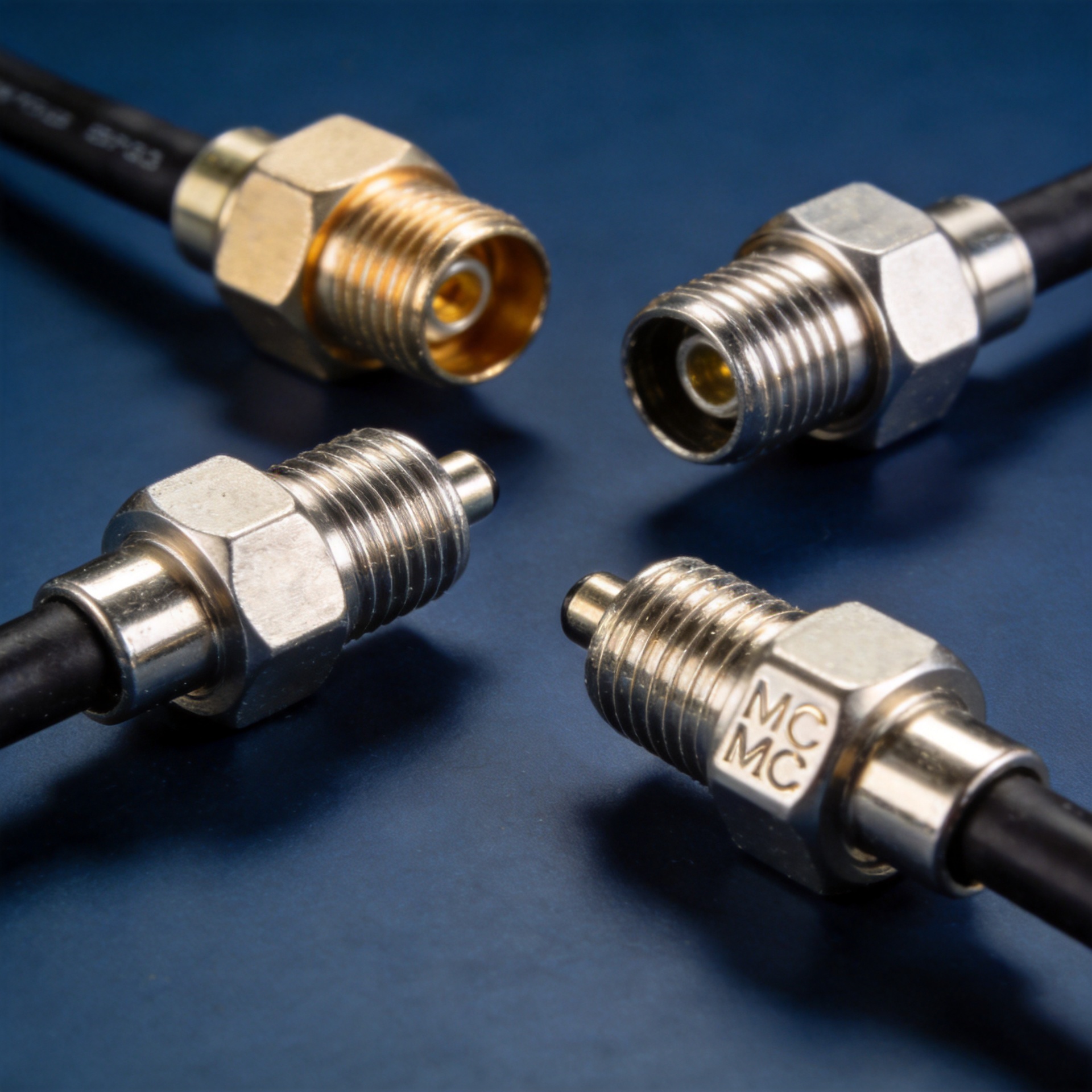
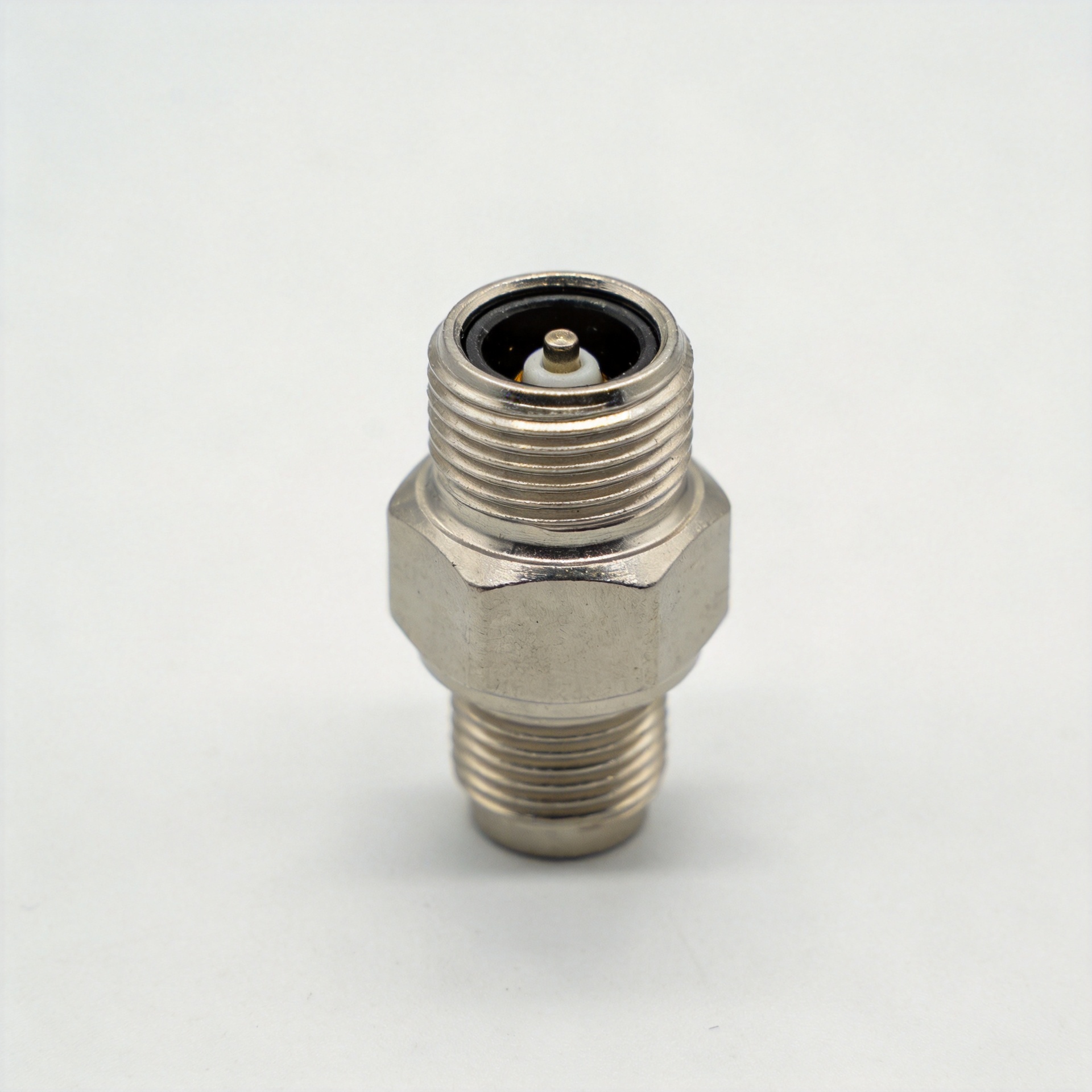
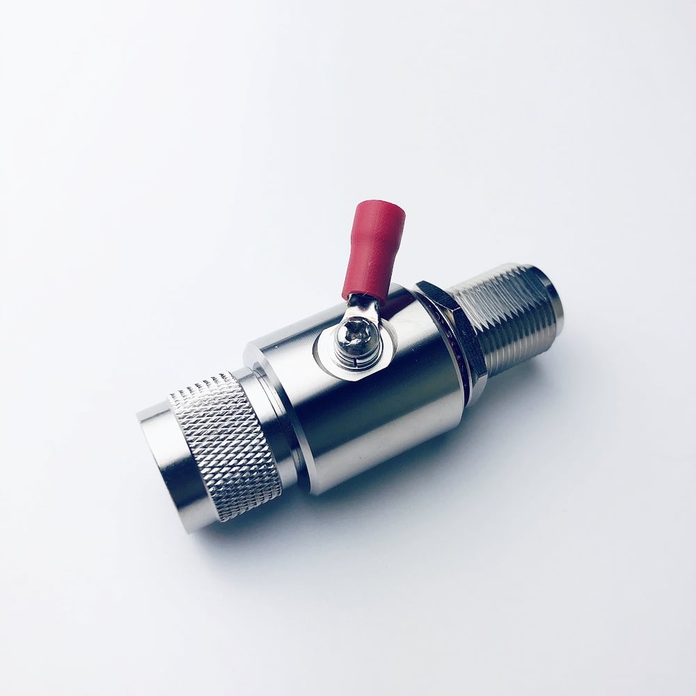
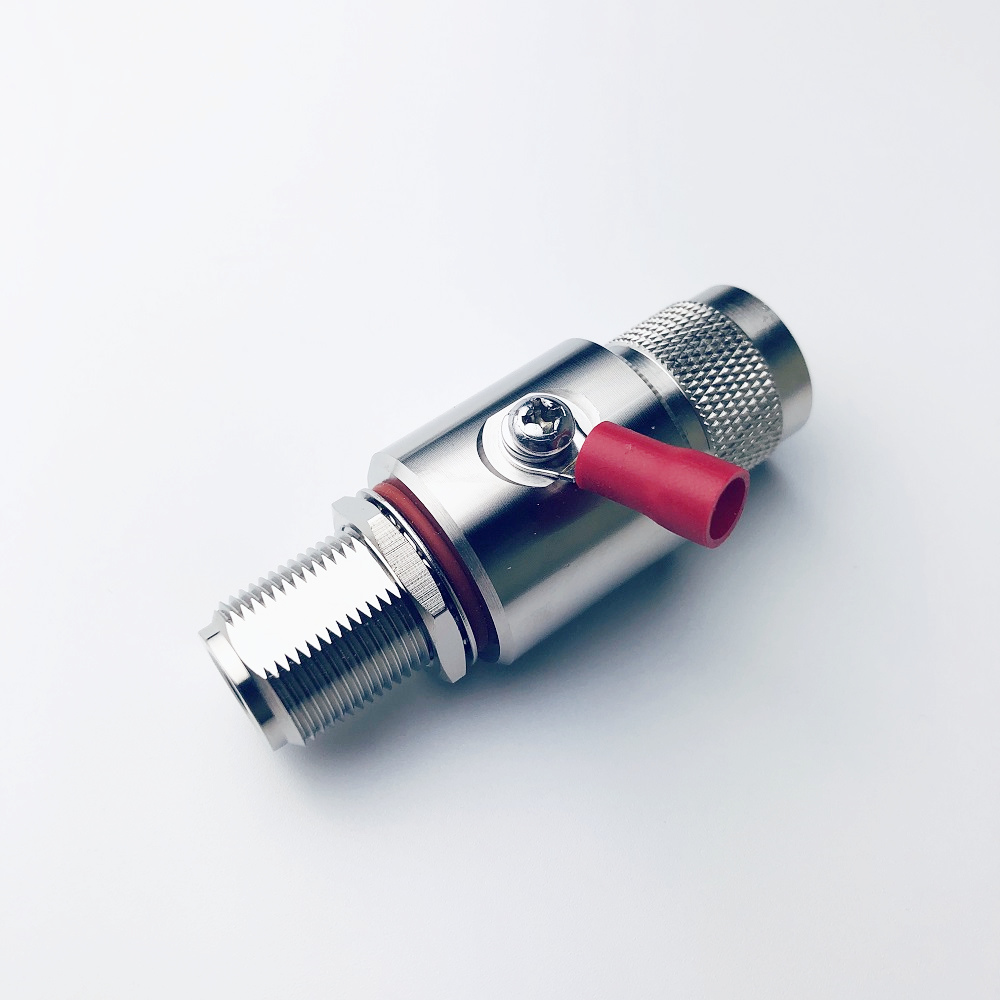
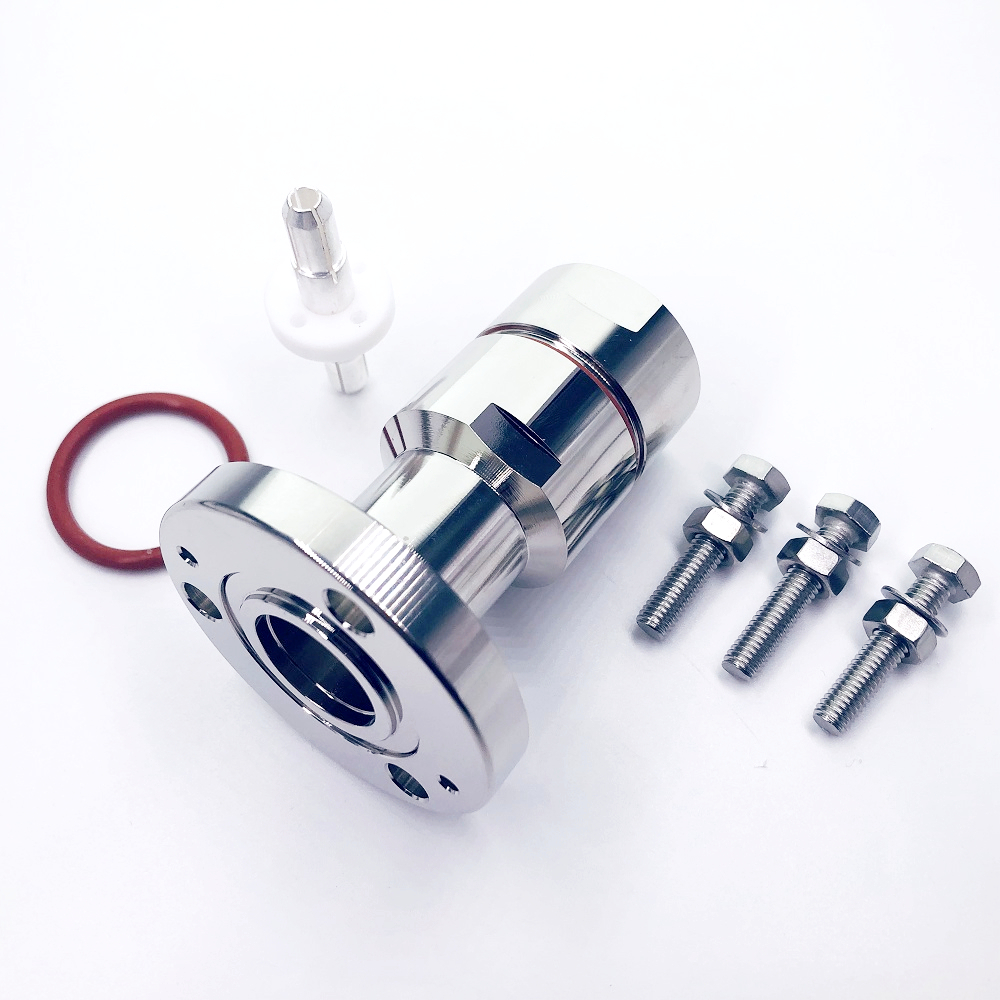
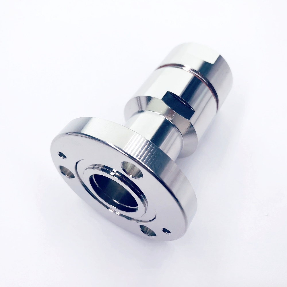
Request comparable RF, surge, environmental, and installation documentation. For a matched site requirement, a N-1/4JKP lightning protector with N male-to-N female interfaces is a product listing to verify against the installed interface and stated 700–2700 MHz range. The listing is not proof of universal suitability.
Use the following handover record to ensure each gdt surge protection decision is documented. It makes gdt surge protection review easier for engineering, procurement, and installation teams.
| gdt surge protection check | gdt surge protection evidence | gdt surge protection owner |
|---|---|---|
| frequency-range check | product datasheet | RF engineer |
| impedance check | design record | RF engineer |
| connector-interface check | BOM record | procurement team |
| insertion-loss check | RF test data | RF engineer |
| VSWR check | RF test data | RF engineer |
| surge-waveform check | surge test report | quality team |
| grounding-route check | site drawing | installer |
| bonding-point check | site inspection | installer |
| torque check | installation checklist | installer |
| weather-sealing check | site inspection | installer |
| labeling check | handover log | site owner |
A practical selection sequence
| Selection step | What to verify | Why it matters |
|---|---|---|
| Map the RF path | Band, impedance, power, connector interfaces, DC requirements | Prevents electrical or mechanical mismatch. |
| Compare RF performance | Frequency range, insertion loss, VSWR/return loss | Protects the signal budget as well as the equipment. |
| Compare surge data | GDT topology, stated waveform, surge-current rating, test basis | Allows meaningful comparison of protection capability. |
| Design the earth path | Bonding point, lead length, conductor routing, equipotential connection | Creates the discharge path the protector relies on. |
| Validate installation | Torque, sealing, mounting, labeling, inspection plan | Maintains performance after commissioning. |
Conclusion: protect the antenna system as a coordinated RF installation
Effective gdt surge protection for 5G antenna feed lines combines the right coaxial protector with disciplined RF and grounding practice. Start with the actual operating band and interface, compare RF and surge specifications under stated conditions, and give the protector a short, robust route to the site's grounding network. When engineering, procurement, and installation teams use the same checklist, the feeder line is more likely to retain its RF performance while limiting surge exposure to downstream equipment.