EN

High-Power RF Attenuator Selection for Telecom Systems
In telecom signal chains, an attenuator is rarely a standalone buying decision. It must work with the transmitter, load, connectors, and high power RF cable assemblies around it. For procurement and engineering teams, the practical question is not simply “Which dB value do we need?” It is whether the selected part can absorb the expected RF energy, stay within temperature limits, preserve impedance control, and connect cleanly to the rest of the installation.
That systems view matters because a high-power attenuator can be electrically correct on a bench yet unsuitable once cable loss, ambient temperature, connector format, duty cycle, and mounting conditions are considered. The following framework helps telecom teams compare options before issuing an RFQ.
Start with the operating condition, not the catalog maximum
Begin by documenting continuous-wave power, peak or pulsed power where applicable, frequency band, expected duty cycle, and installation environment. A nameplate power rating is useful only when its stated test conditions resemble the real application. Thermal behavior is central: high-power coaxial attenuator design balances power handling and frequency capability, so a choice made only on wattage can create an avoidable compromise.
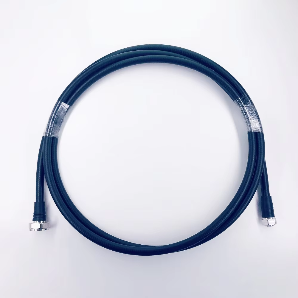
For example, an attenuator placed in a compact indoor enclosure may have less opportunity to shed heat than the same part mounted on a conductive panel with airflow. Build reasonable engineering margin into the selection and ask the supplier for derating guidance at the anticipated ambient temperature. This is also the point to verify how the nearby high power RF cable assemblies are routed; tight bends, inadequate strain relief, or heat trapped near the connector can reduce the robustness of the complete path.
Match attenuation value to the job the component performs
Attenuation value should follow a defined system purpose. Common purposes include protecting a receiver input, establishing a known test level, reducing excessive drive, improving level matching between stages, or providing a controlled load condition. Specify the required attenuation in dB together with the allowed tolerance across the relevant frequency range. A nominal value without tolerance may be insufficient for a measurement path or a narrow signal budget.
Also separate attenuation from power dissipation in the RFQ. The attenuator must safely handle the input conditions, while the downstream equipment must be compatible with the resulting output level. When a cable run is involved, account for its insertion loss rather than treating the attenuator and cable as independent items. This creates a more realistic budget for high power RF cable assemblies and the passive components connected to them.
Evaluate frequency range, impedance, and VSWR together
Most telecom RF paths expect a controlled characteristic impedance, commonly 50 ohms. The attenuator, connectors, and cable assemblies should use the same impedance unless the design intentionally includes a matching function. Frequency range must cover the highest operating frequency with suitable performance margin; a part that reaches the target band in a catalog is not automatically appropriate if VSWR, attenuation flatness, or connector behavior becomes marginal near the band edge.
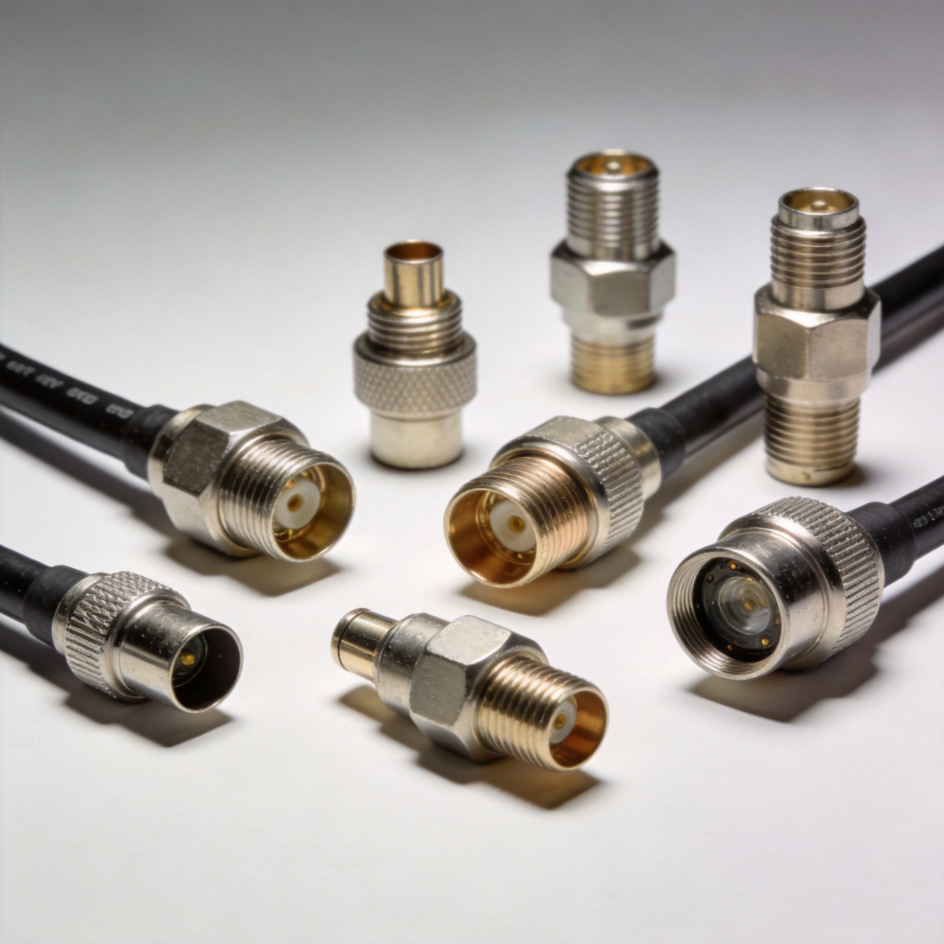
Request the relevant electrical data at the frequencies that matter to your deployment: attenuation tolerance, VSWR or return loss, and power rating under the intended operating conditions. For high-frequency paths, the interface is part of the electrical design. Connector family, gender, torque practice, and adapter count affect repeatability. Fewer unnecessary transitions usually make it easier to maintain a predictable signal path with high power RF cable assemblies.
Compare mechanical and thermal interfaces before choosing a connector
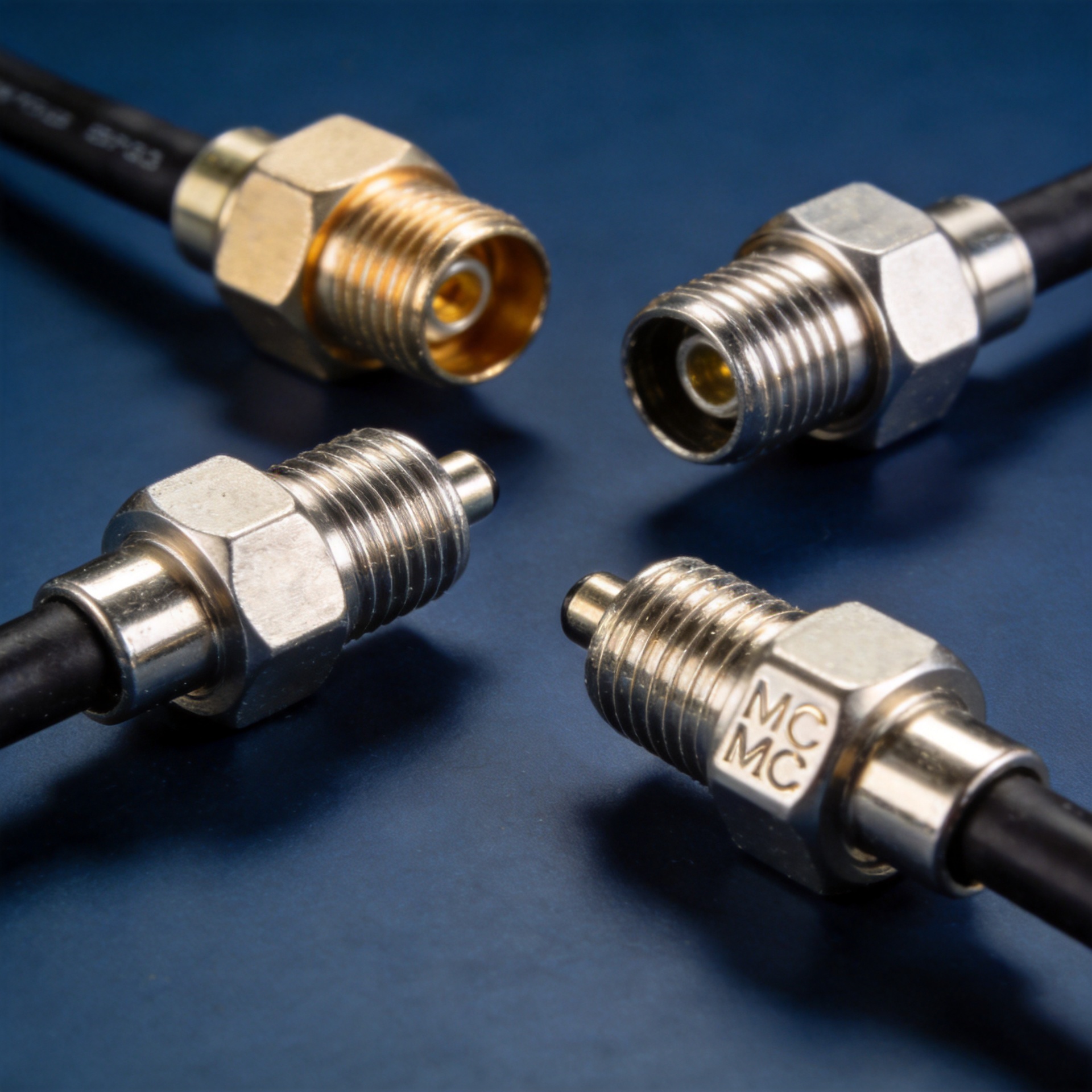
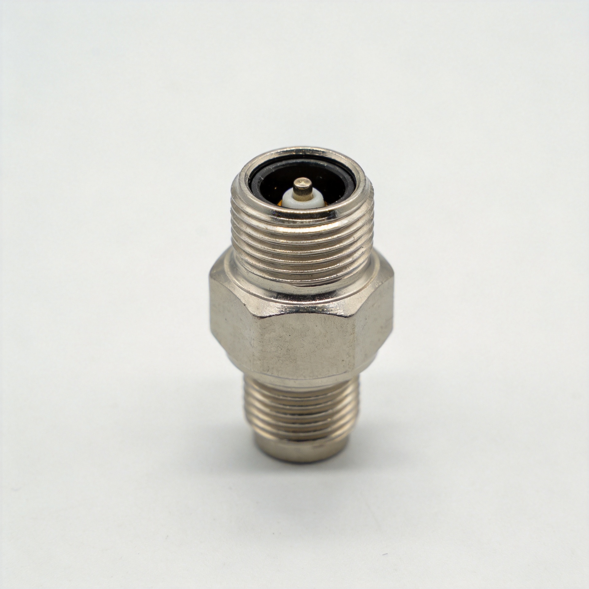
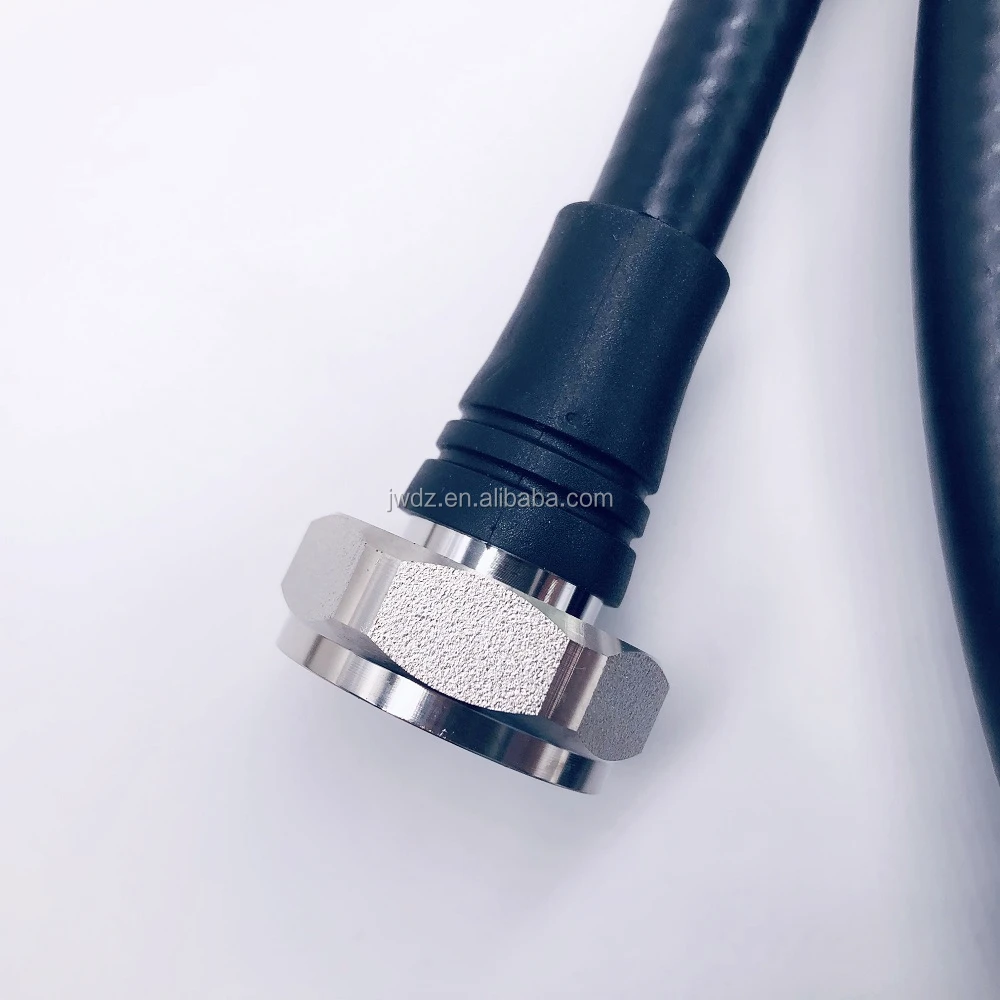
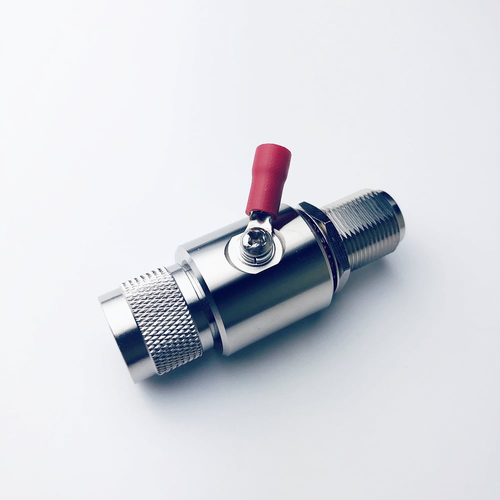
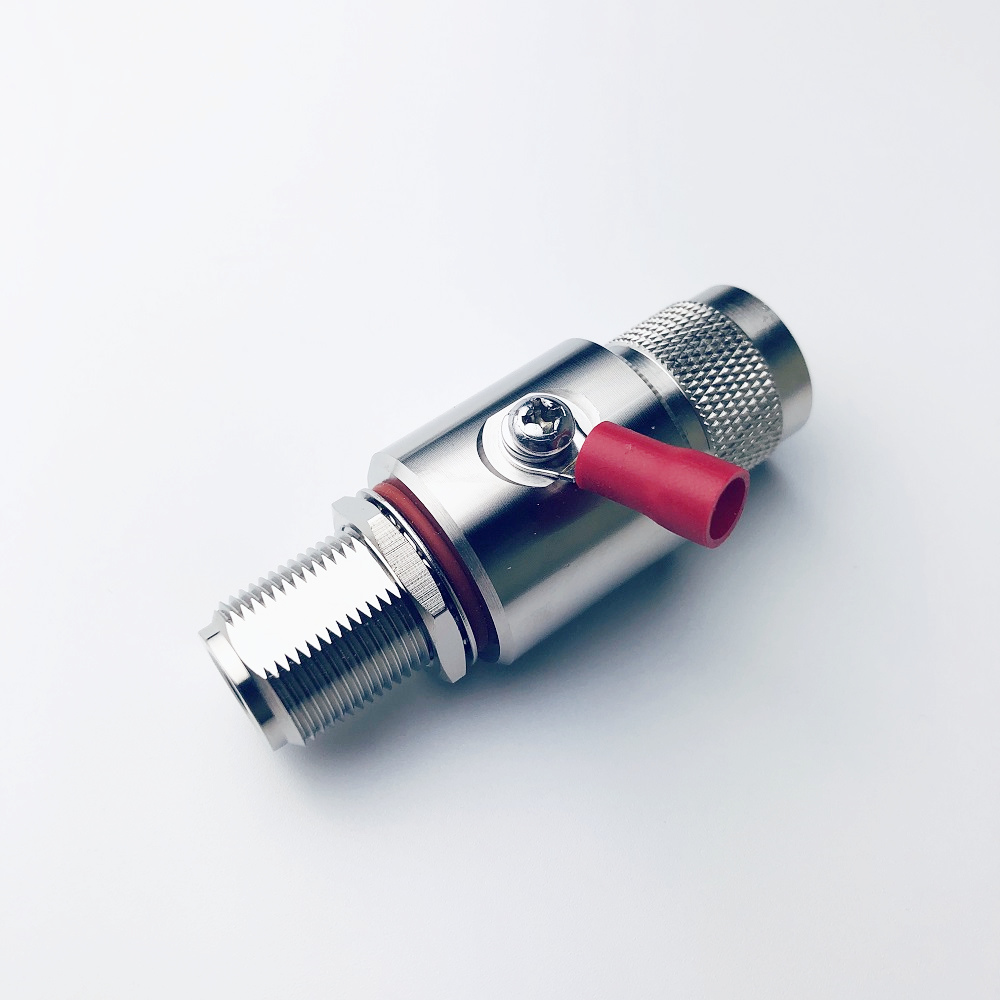
Connector selection is more than convenience. N-type, 7/16 DIN, and other coaxial interfaces differ in their mechanical envelope, frequency capability, mating practice, and suitability for the surrounding equipment. Choose the interface that matches the existing system and minimizes adapters. Then confirm whether the attenuator body needs chassis mounting, a heat sink, or clear airflow to meet its rating.
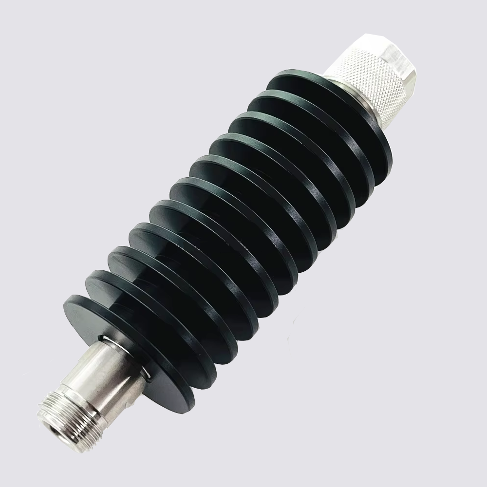
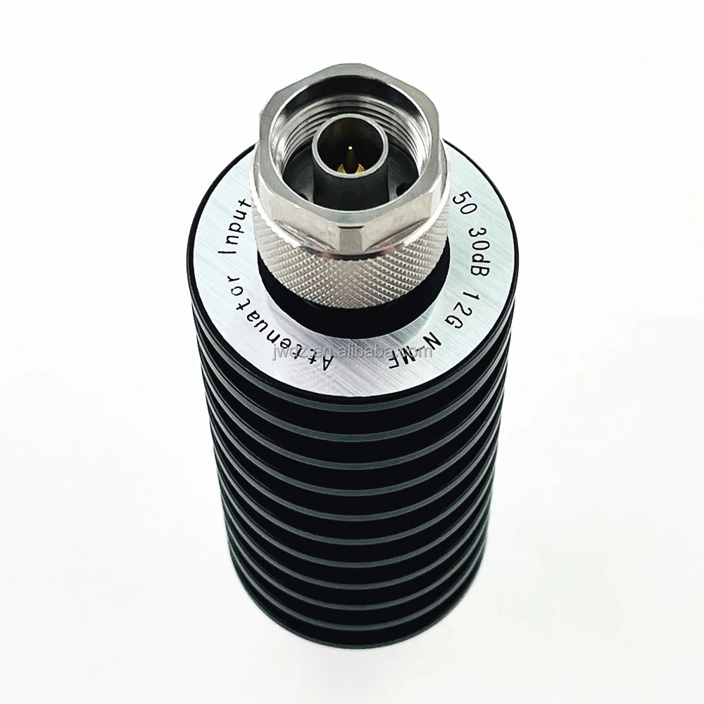
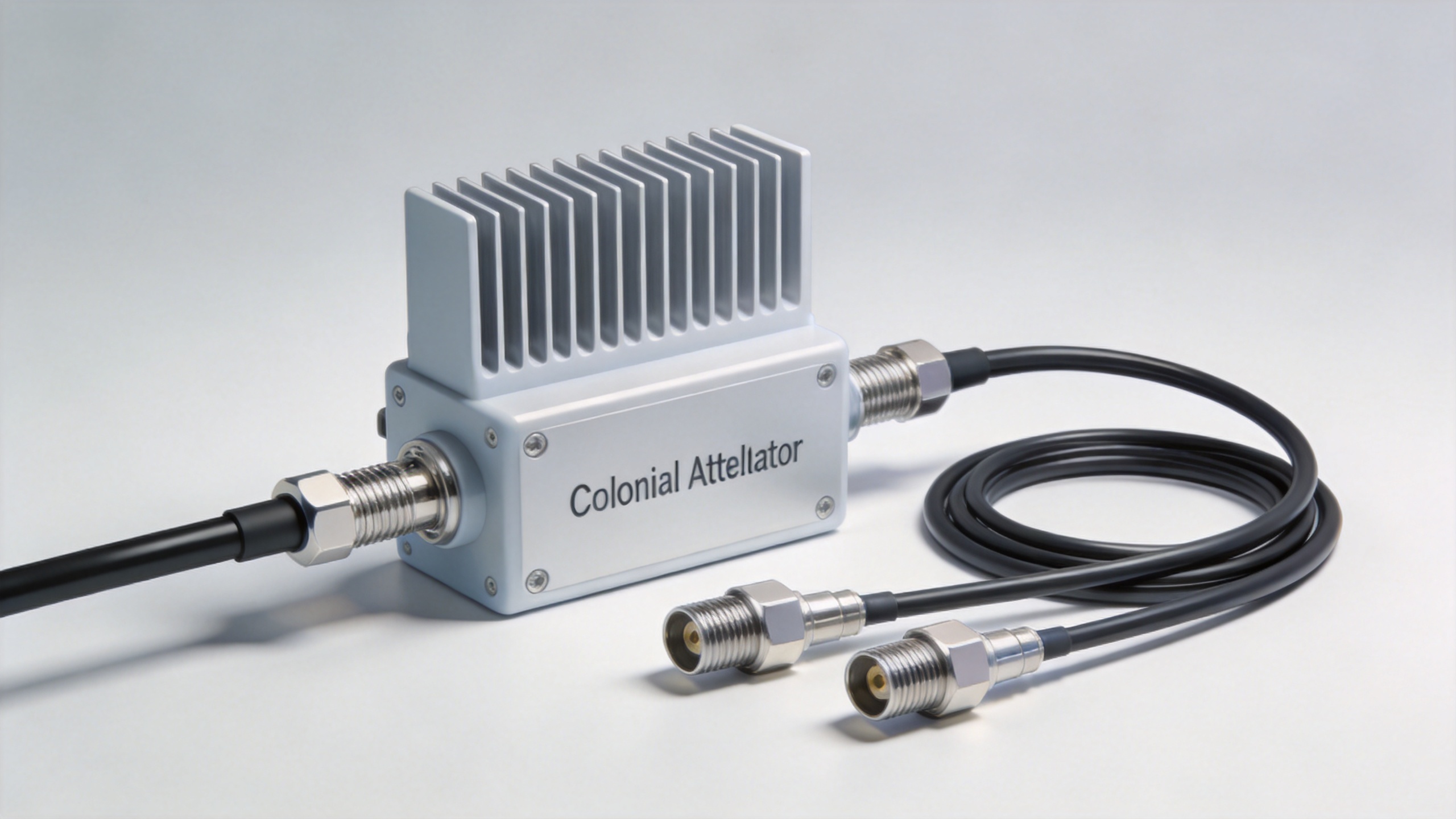
For an application that requires an N-interface component, a real product option is the 200W DC–18GHz N Coaxial Attenuator. Its product title identifies a 200 W class, DC-to-18 GHz coverage, N coaxial interface, and listed 20 dB, 30 dB, 40 dB, and 60 dB attenuation options. Confirm the current datasheet, connector configuration, and thermal installation conditions against your own project requirements before selection.
Use a telecom procurement comparison table
| Selection factor | What to define | Why it matters |
|---|---|---|
| Power and duty cycle | Continuous, peak, pulse, ambient temperature, and mounting condition | Determines heat load and whether derating is needed. |
| Frequency performance | Operating band, attenuation tolerance, VSWR or return loss | Protects signal integrity across the intended band. |
| Attenuation value | Required dB, tolerance, and system purpose | Ensures the output level supports the next stage. |
| Interface | Impedance, connector family, gender, adapter policy, torque practice | Reduces mismatch and mechanical rework. |
| Integration | Cable type, bend allowance, routing, strain relief, and service access | Aligns the attenuator with high power RF cable assemblies as one controlled path. |
Build the RFQ around measurable acceptance criteria
A useful RFQ asks for more than a part number. State the frequency range, nominal attenuation and tolerance, impedance, maximum input condition, duty cycle, preferred connector configuration, environmental conditions, mounting arrangement, and quantity. Ask whether the quoted rating assumes free air, heat sinking, or a specified temperature. If replacement and maintenance are important, include marking, traceability expectations, and consistency requirements for recurring supply.
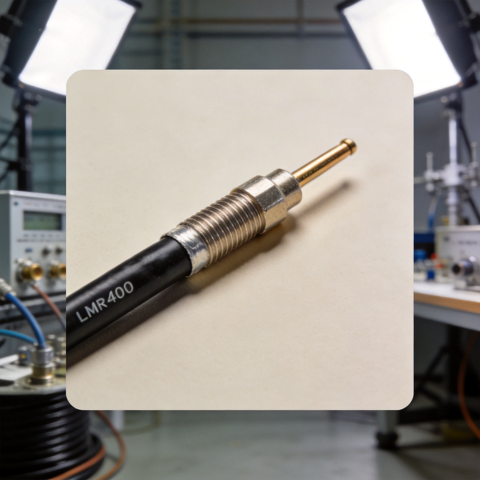
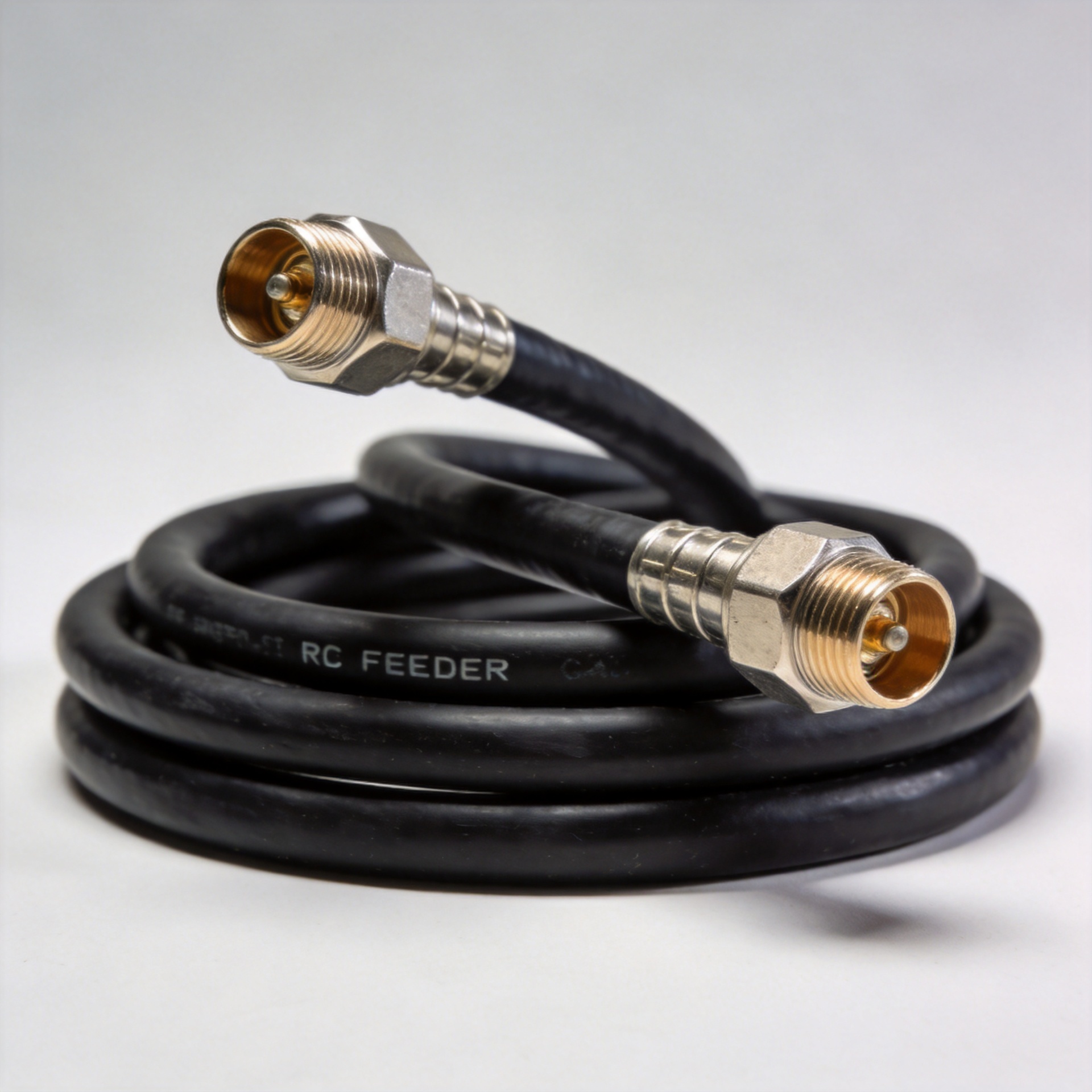
For cable-connected systems, specify mating interfaces on both sides and identify whether high power RF cable assemblies are supplied separately or as part of the solution. A supplier that understands connectors, feeder cables, cable assemblies, and RF loads can help reduce interface ambiguity across the BOM, but the final acceptance criteria should remain tied to the project’s measurable requirements.
Final selection checklist
- Does the frequency range cover the operating band with suitable electrical margin?
- Is the attenuation value and tolerance suitable for the actual signal-level objective?
- Is the power rating valid for the intended duty cycle, ambient temperature, and mounting condition?
- Are impedance, connector interfaces, and mating practices compatible across all high power RF cable assemblies?
- Can the attenuator dissipate heat without obstructing cable routing or future service?
- Does the RFQ request the data needed to verify the quoted configuration?
The appropriate high-power attenuator is application-specific. By comparing thermal capacity, frequency performance, attenuation tolerance, and interface compatibility as a single decision, telecom teams can select a component that supports a stable RF path rather than merely satisfying one catalog line.