EN

How to Choose a DAS Antenna for Indoor Wireless Coverage
Choosing a DAS antenna is not a matter of picking the widest frequency range from a catalog. In an indoor distributed antenna system, every antenna is one part of a signal path that also includes the signal source, feeder cables, splitters, couplers, connectors, and installation workmanship. A sound choice starts with the building coverage objective and works backward to the antenna specification.
For network architects planning offices, hotels, hospitals, transit areas, or large commercial interiors, the goal is usually the same: consistent usable wireless service where a macro signal cannot reliably reach. The right DAS antenna supports that goal by matching the operating bands, coverage geometry, RF budget, and physical constraints of the site. This guide turns those checks into a practical selection sequence.
Start with the indoor coverage requirement, not the antenna catalog
Before comparing a DAS antenna, define what the system must cover. Mark the usable floor area, ceiling heights, partitions, lift shafts, corridors, high-occupancy zones, and spaces where signal quality is business-critical. Then confirm whether the project is designed for cellular, private radio, Wi-Fi integration, public-safety communications, or a combination of services.
A distributed antenna system uses spatially separated radiating nodes to extend a common signal source through a building. That means antenna count and placement are linked to the RF design, not simply to room size. Dense areas may need more carefully placed radiators, while open spaces may allow a broader pattern and longer spacing. If you only compare one antenna gain figure, you can miss the interaction between antenna placement, cable loss, splitter loss, and the actual materials in the building.
Here is the question worth asking before approving a bill of materials: what coverage and capacity result does each antenna location need to achieve after the entire distribution path is included? That answer should guide every later specification.
Step 1: Match the DAS antenna frequency range to the live and planned bands
DAS antenna selection should be documented in the RF design. For each DAS antenna, record the intended zone, operating bands, port configuration, and acceptance criteria. This makes every DAS antenna choice traceable during commissioning.
The first technical filter is frequency coverage. A DAS antenna must support every band carried by the indoor system today, with enough range for the approved expansion plan. A wideband model can simplify multi-band projects, but wideband alone is not a universal advantage. Select the range that fits the design rather than paying for unused margin.
For example, product offerings in the market include wideband indoor DAS antennas covering ranges such as 350–6000 MHz. That range may be suitable for certain multi-operator or multi-service designs, but the selected product datasheet still needs to be checked against your exact bands, port configuration, and system architecture. A 380–6000 MHz option may be relevant when its documented specifications align with the project requirements, such as this 380–6000 MHz low-PIM indoor MIMO omni antenna with N-female connector.
Also confirm whether the system needs single-port coverage, dual-polarized operation, or MIMO support. A frequency range that looks correct on paper can still be the wrong fit if the number of ports, polarization arrangement, or connector interface does not match the distribution design.
Step 2: Choose the radiation pattern around the building geometry
DAS antenna selection should be documented in the RF design. For each DAS antenna, record the intended zone, operating bands, port configuration, and acceptance criteria. This makes every DAS antenna choice traceable during commissioning.
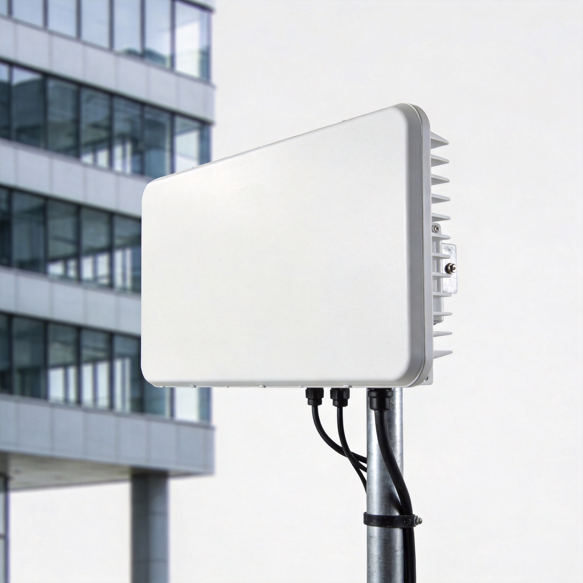
Indoor DAS antenna selection normally comes down to how the antenna radiates into its intended zone. Omnidirectional ceiling antennas are often practical where a uniform horizontal pattern supports open rooms, lobbies, or general floor coverage. Directional antennas can be useful when coverage must be focused along corridors, into a particular room, or away from a sensitive boundary.
At its simplest, gain describes how a DAS antenna concentrates energy in a direction. The complicating factor is that more gain is not automatically better. A higher-gain pattern may create an unwanted coverage shape in a low-ceiling room or leave weak areas where the design assumed a broader beam. Start from the mounting location and target area, then review the pattern data and downtilt or beamwidth requirements with the RF design team.
| Indoor condition | Selection question | Typical direction |
|---|---|---|
| Open office or lobby | Is broadly distributed horizontal coverage needed? | Evaluate an omni pattern. |
| Long corridor | Should energy be concentrated along a narrow path? | Evaluate a directional pattern. |
| High ceiling or atrium | Will height and beamwidth maintain the required signal level at user height? | Model the pattern and placement before choosing gain. |
| Multi-room floor plate | Will walls or fire-rated partitions create shadowing? | Use the RF plan to determine antenna density and location. |
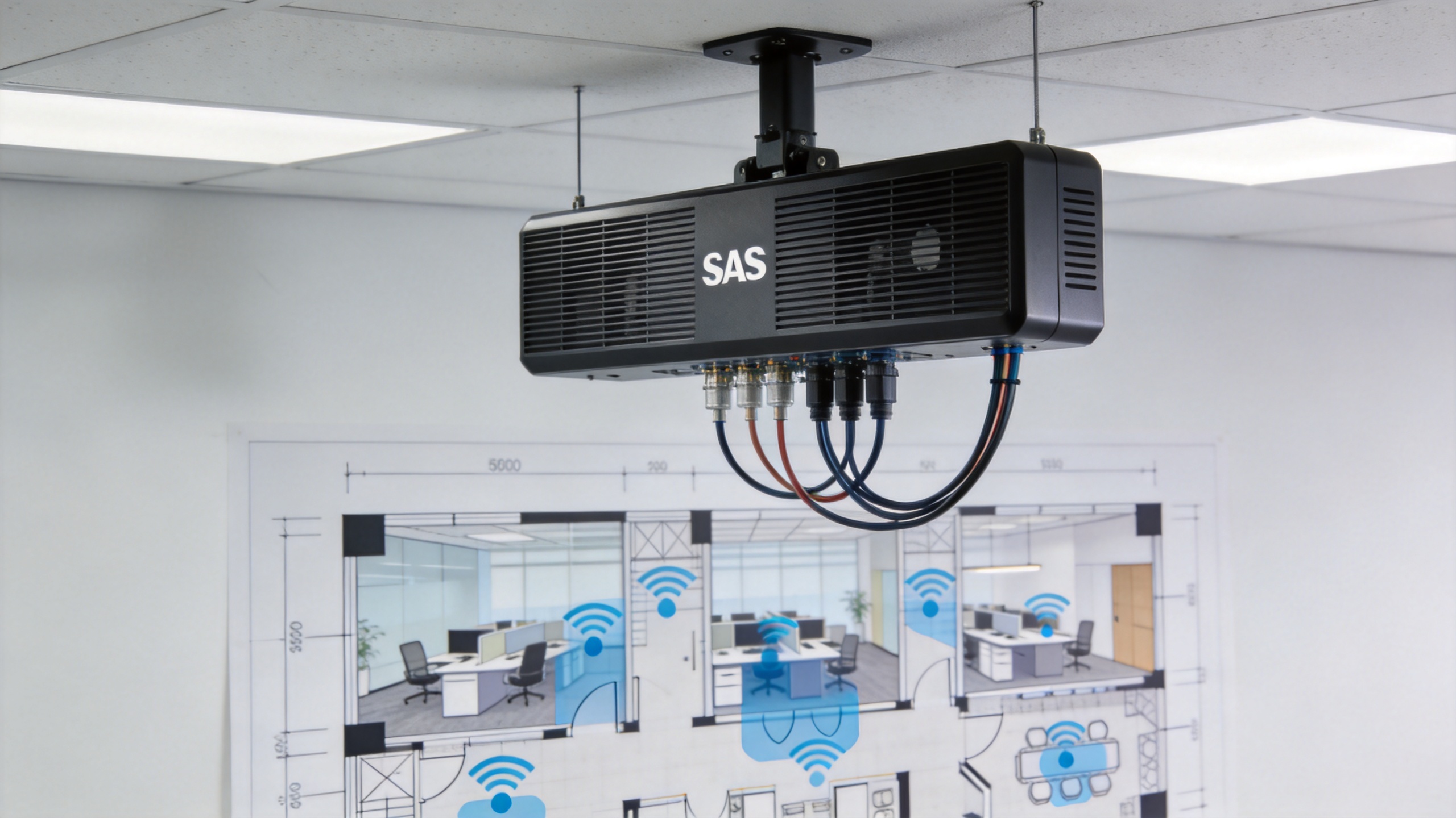
Step 3: Review the RF specifications as a system, especially PIM and VSWR
DAS antenna selection should be documented in the RF design. For each DAS antenna, record the intended zone, operating bands, port configuration, and acceptance criteria. This makes every DAS antenna choice traceable during commissioning.
For multi-carrier indoor deployments, low passive intermodulation (PIM) performance deserves attention. PIM can create unwanted signals when multiple carriers pass through passive RF components. The antenna is not the only contributor: cables, connectors, adapters, splitters, mechanical joints, and installation conditions also affect the result. A low-PIM DAS antenna supports a cleaner RF path, but it cannot compensate for poor connector seating or incompatible components elsewhere in the system.
VSWR and return loss are equally important because they indicate how well the antenna interface is matched to the RF system. It is tempting to focus only on insertion loss. It is not, quite, the complete story. Reflections caused by a poor match can reduce effective performance and complicate commissioning. Compare each antenna against the same impedance, frequency, and test-condition baseline used for the rest of the design.
Ask suppliers for a current datasheet and make the RFQ explicit about the tests you need to review. Useful checks include the frequency range, impedance, VSWR or return loss, PIM condition and measurement setup, gain/pattern data, polarization, maximum input power, connector type, and installation method. Do not treat a product family name as a substitute for a project-specific specification review.
Step 4: Check physical integration before the installation team arrives
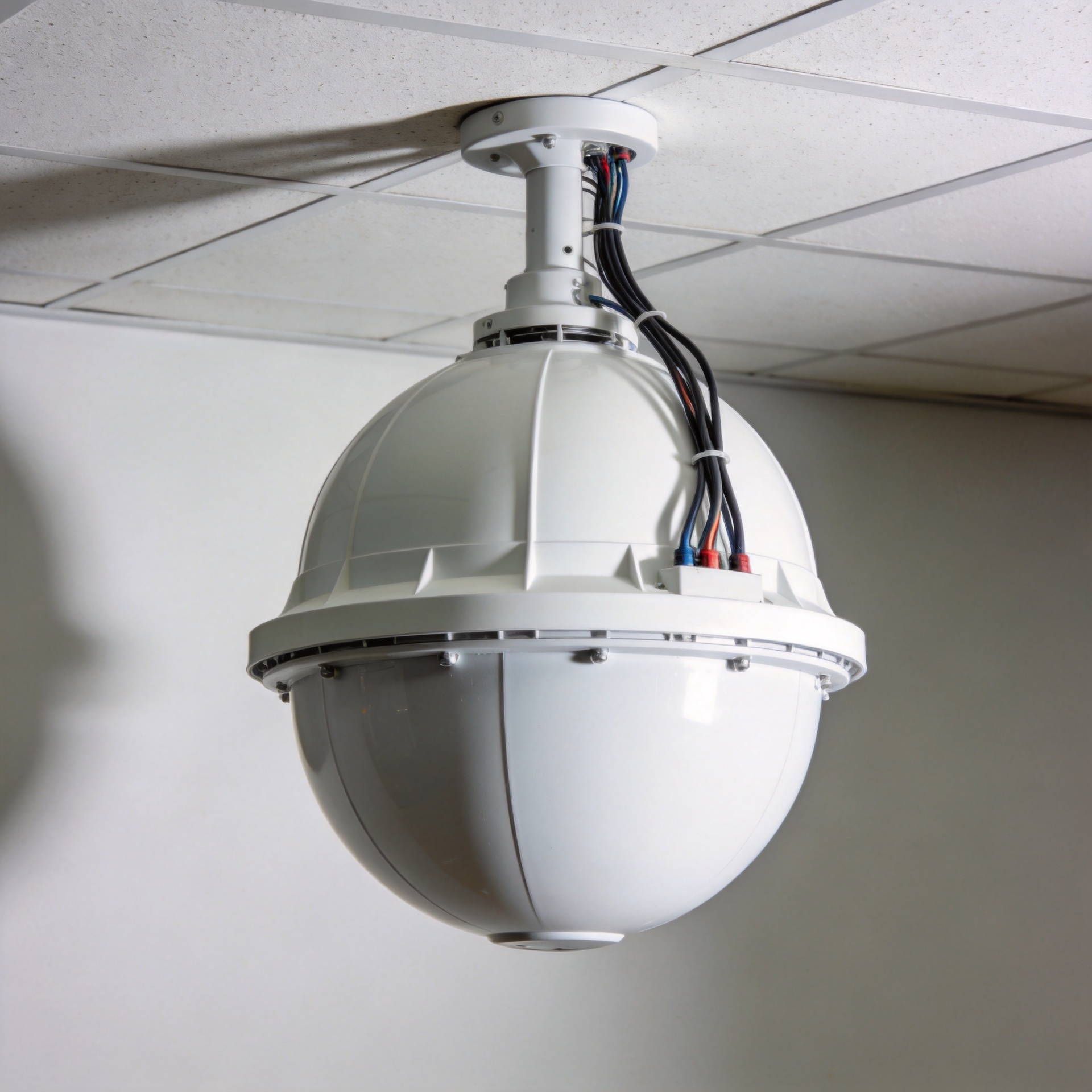
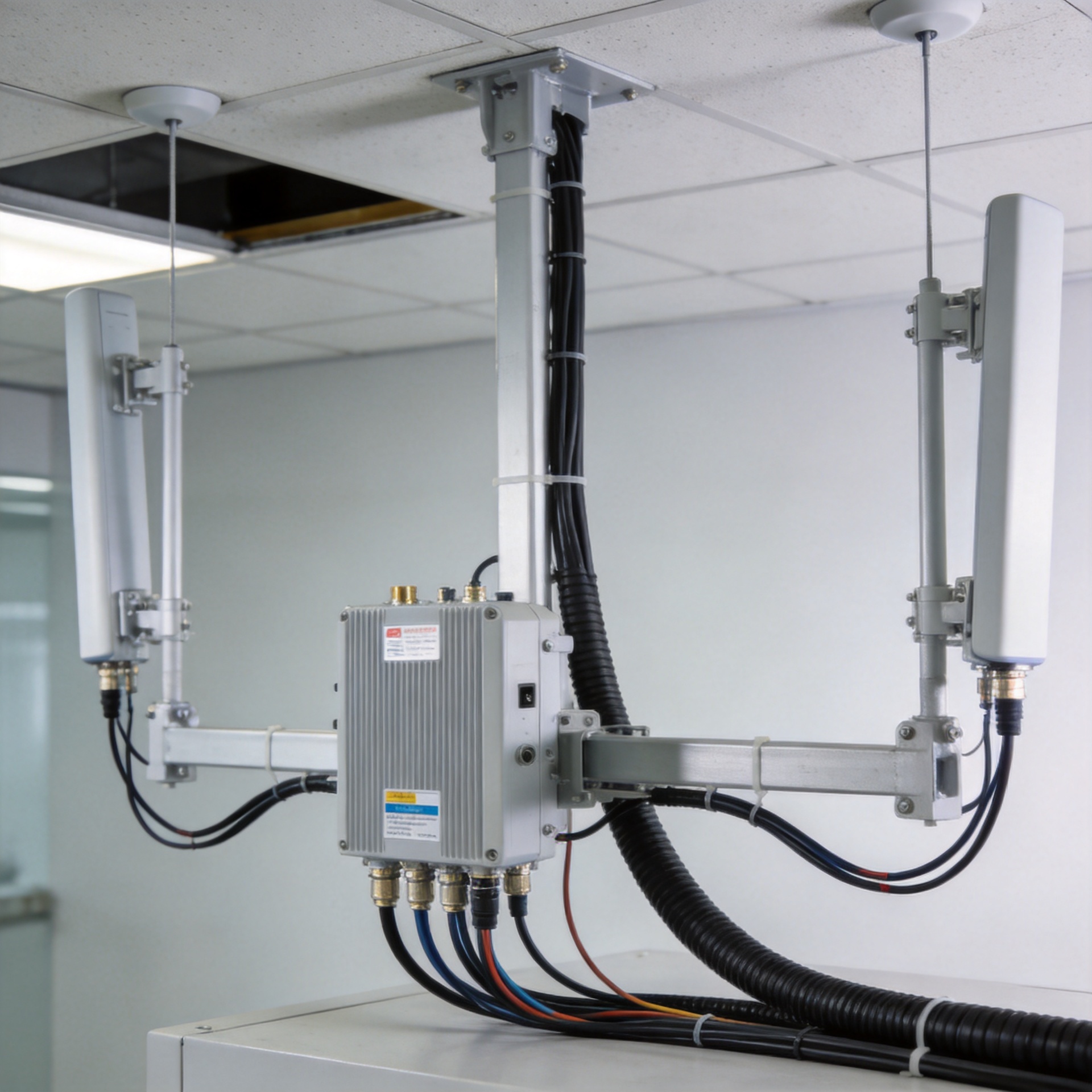
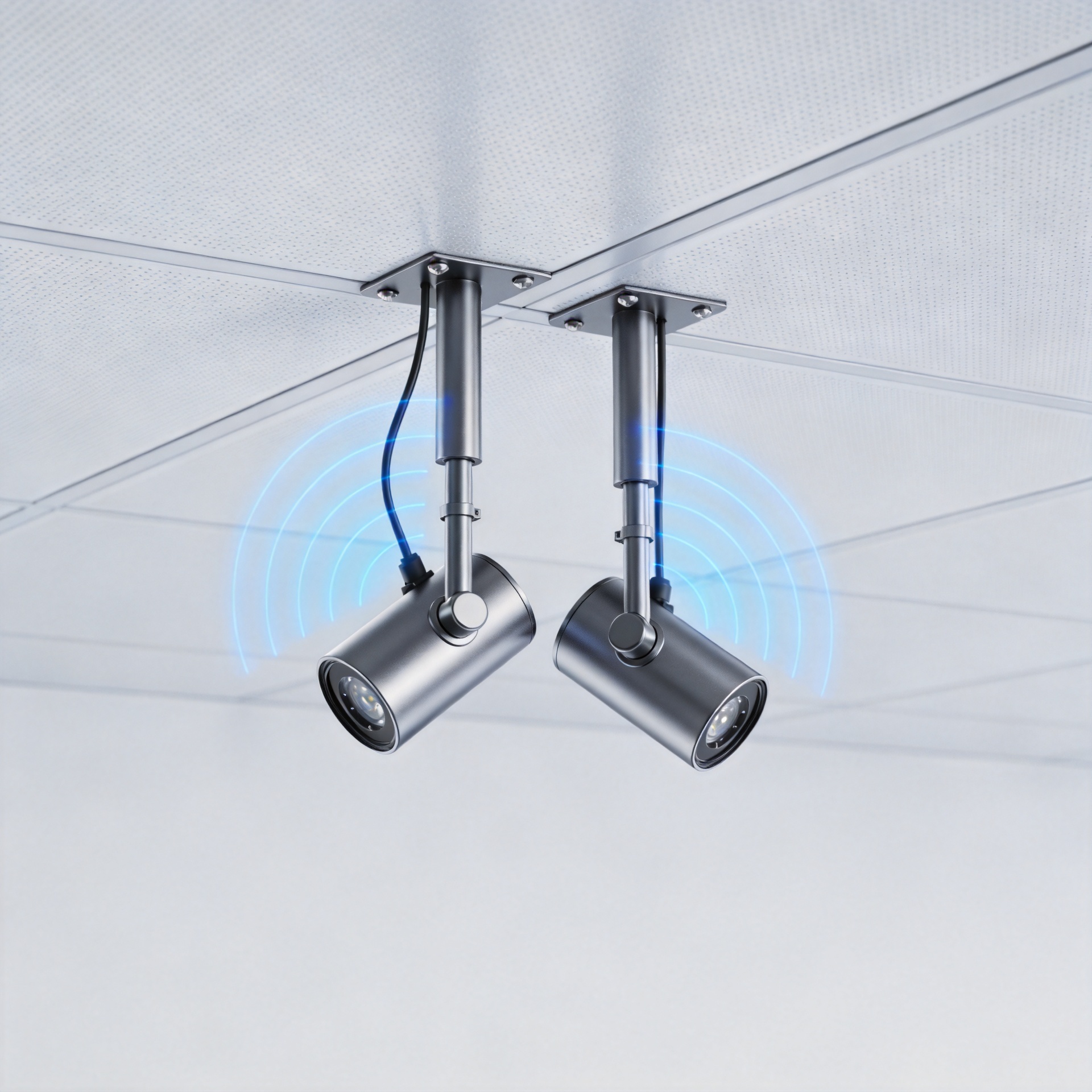
A DAS antenna has to fit the ceiling, mounting method, plenum rules, cable routing, and maintenance access plan. Verify the antenna body dimensions, mounting hardware, connector orientation, feeder bend radius, and clearance above the ceiling. In indoor projects, a technically suitable antenna can still create delays if the connector cannot be accessed after mounting or if a cable route forces an excessive bend.
Think of the RF path as a chain: the antenna may be correctly specified, but the installation quality determines whether its performance reaches the design target. Confirm torque requirements where applicable, protect connector interfaces during handling, and include a commissioning test plan. Field measurements that differ from the modeled result often point to an installation variable that the model did not include.
Step 5: Use a practical DAS antenna comparison checklist
For a consideration-stage purchase decision, compare candidate antennas using one consistent checklist rather than a mixture of supplier marketing claims.
- Services and bands: List the active and planned bands, then reject any DAS antenna that does not cover the required range.
- Coverage pattern: Match omni or directional behavior to the modeled zone, ceiling height, and nearby obstructions.
- RF integrity: Review impedance, VSWR/return loss, PIM requirements, power handling, and the test conditions behind each claim.
- Ports and polarization: Confirm the port count, MIMO or polarization needs, and the connector type used by the feeder network.
- Mechanical fit: Check ceiling mount details, connector access, cable routing, and visual finish for the indoor space.
- Supply consistency: Qualify the manufacturer’s ability to provide consistent parts, current documentation, and compatible RF interconnect components for the project BOM.
- Acceptance testing: Define how the antenna installation and the completed RF path will be verified before handover.
Make the final choice from the whole DAS design
The right DAS antenna for indoor wireless coverage is the one that fits the RF plan, not the one with the longest feature list. Start with required bands and the coverage model, choose a radiation pattern for the physical zone, verify PIM and matching performance in the context of the entire RF path, and confirm that the antenna can be installed and tested properly.
For procurement teams, this approach also makes supplier discussions clearer. Instead of asking for a generic indoor antenna, provide the system bands, antenna locations, port requirements, target RF metrics, connector interface, mounting constraints, and required documentation. That converts selection from a catalog comparison into an engineering decision that is easier to validate before deployment.