EN

How to Choose a MIMO 5G Antenna for Indoor Coverage
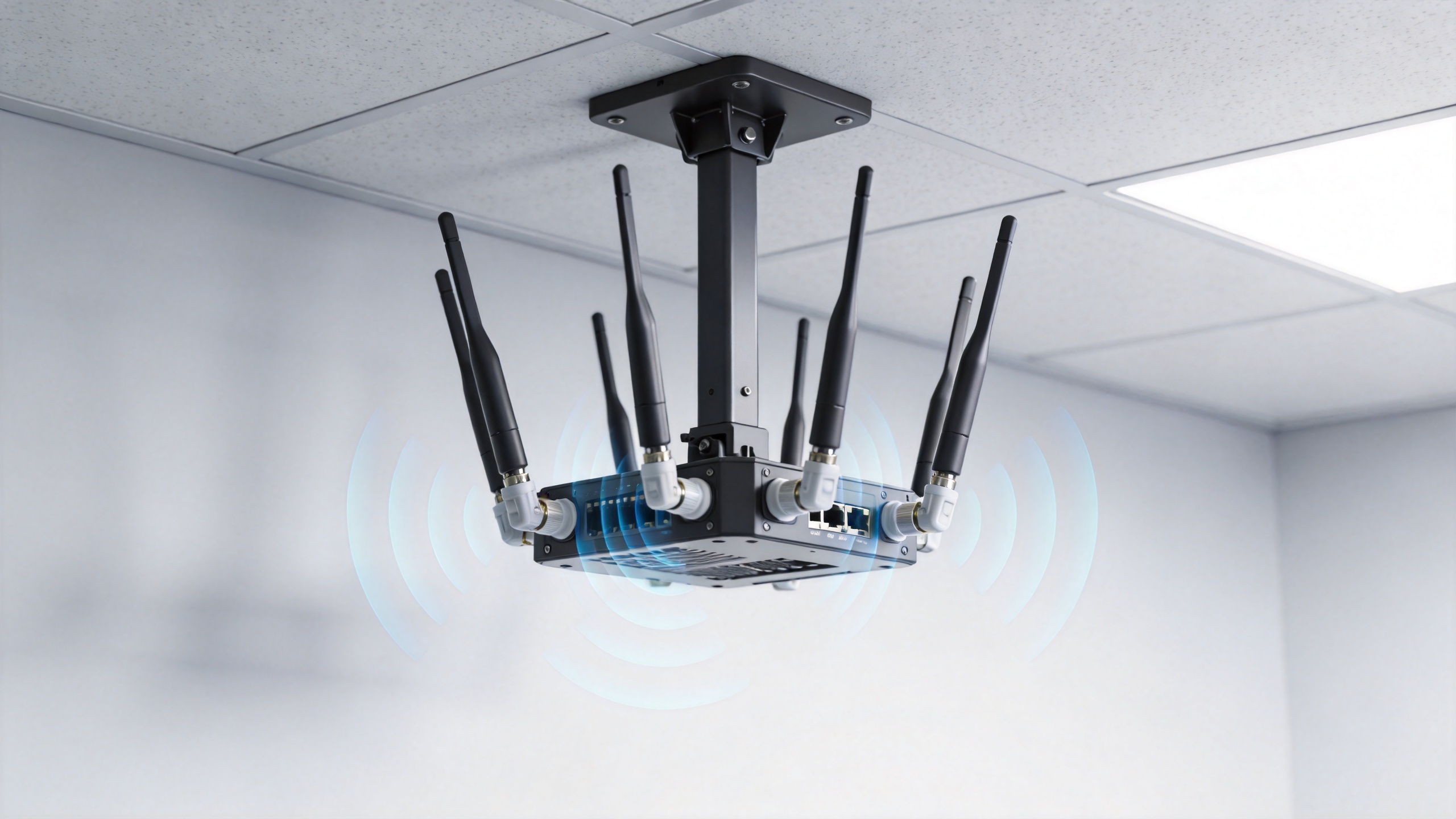
Indoor 5G projects rarely fail because a buyer forgot to order an antenna. They fail when the selected antenna, radio ports, feeder path, and room layout do not work as one RF system. For a telecom procurement team, choosing an antenna mimo 5g solution means matching the antenna to the operator bands, the available MIMO ports, the desired coverage pattern, and the practical constraints above the ceiling.
This guide provides a comparison framework for offices, corridors, retail floors, public areas, and other distributed antenna system (DAS) environments. It focuses on coverage antennas, not vehicle or terminal-side accessories. The aim is to help buyers write a usable specification before installation begins.
Start with the indoor coverage problem
Document the space before comparing antenna catalogs. A single open floor, a hotel corridor, a lift lobby, and a partitioned office create different propagation paths. Building materials, glass, metal racks, fire doors, and enclosed rooms all influence where RF energy reaches users. A ceiling-mounted omni antenna may be suitable for a relatively open zone; a long corridor or a weak edge area may need a different placement plan or a directional element selected by the RF design.
Define four items: the bands to be supported, the number of radio chains, the intended coverage zones, and the cable route. This prevents a common purchasing mistake: treating a broad frequency label as proof that the complete indoor system will perform as required.
Match frequency coverage to the actual 5G band plan
The first test for an antenna mimo 5g purchase is frequency compatibility. Confirm the licensed bands used by the operator, the radio unit, and any planned future layers. 5G NR includes FR1 from 410 MHz to 7125 MHz and FR2 from 24.25 GHz to 71 GHz, but that classification does not make every wideband antenna suitable for every deployment. Indoor DAS projects commonly require a practical band combination rather than the widest possible headline range.
Compare the antenna datasheet against the actual operating bands and the passive components in the path. Splitters, couplers, jumpers, connectors, and feeder cable must also be appropriate for the chosen frequencies. If an older indoor system supports only legacy bands, confirm whether its passive network constrains the planned 5G layer before specifying the antenna.
Choose 2x2 or 4x4 MIMO based on the radio architecture
MIMO uses multiple signal paths to support capacity and reliability when the radio and propagation environment can use them. A 2x2 MIMO arrangement is often the practical starting point where the radio exposes two relevant RF paths and the coverage objective is straightforward. A 4x4 MIMO design can be considered when the radio architecture, port count, feeder plan, and capacity objective all justify four paths.
Do not select 4x4 simply because it appears more advanced. Each additional path can add ports, feeder runs, passive components, installation work, and validation effort. First verify the radio ports and the designed DAS topology. Then assess whether the indoor traffic profile and spatial environment support the added complexity. The correct antenna mimo 5g configuration is the one that preserves independent paths without creating an unmanageable installation.
Check polarization, port isolation, and pattern together
For indoor MIMO coverage, polarization is part of the system decision, not a decorative datasheet field. Cross-polarized ports are commonly used to help create less-correlated signal paths. The effectiveness still depends on antenna design, surrounding objects, spacing, cable routing, and the local multipath environment. Review the manufacturer’s port arrangement, isolation information, and radiation-pattern documentation alongside the MIMO order.
Also match the radiation pattern to the mounting location. An omni indoor antenna can distribute energy around a ceiling location, while a directional antenna may suit a targeted zone when an RF plan calls for it. Avoid judging coverage from gain alone. Higher gain changes the shape of the pattern; it does not automatically improve every room or overcome poor placement.
Specify the connector and feeder interface early
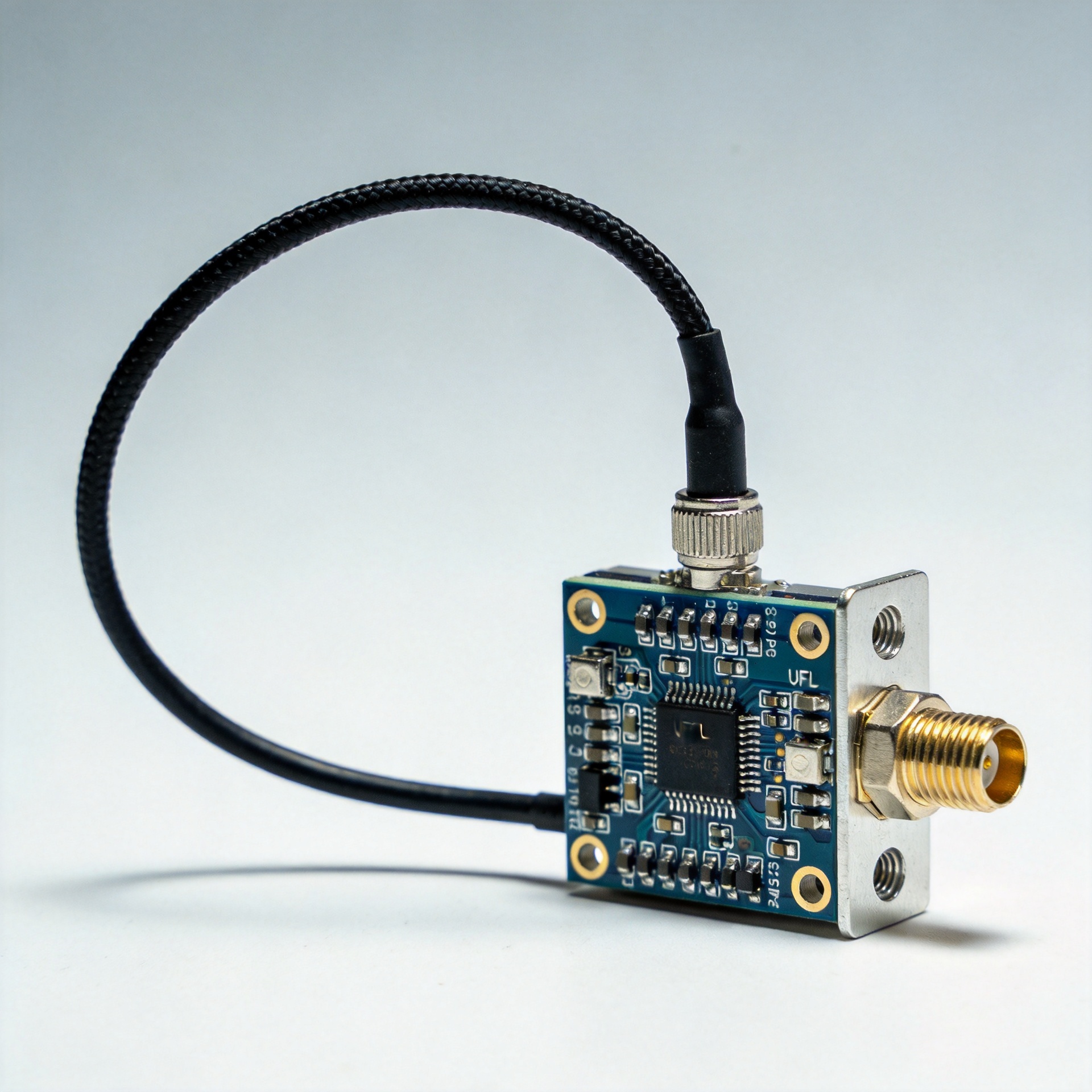
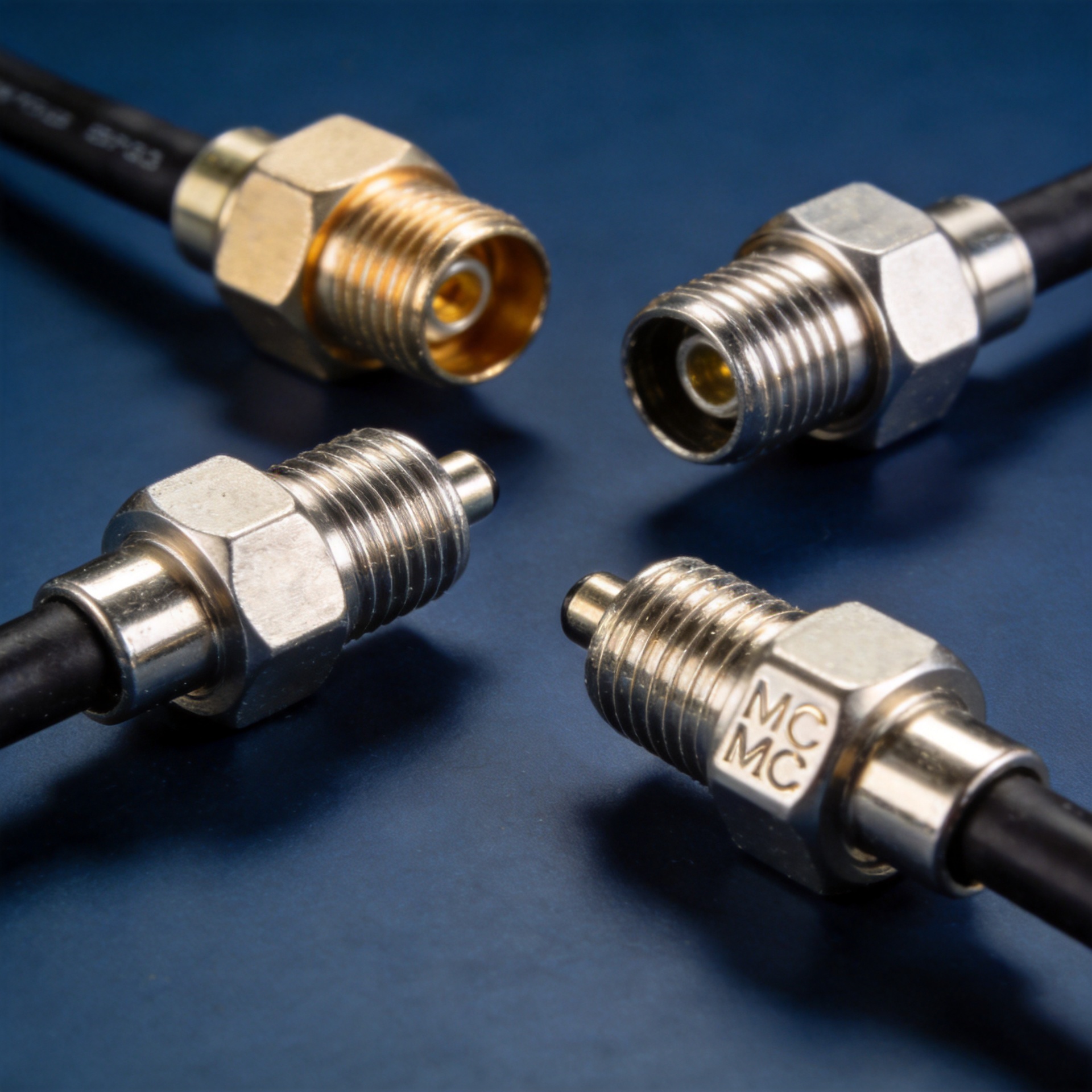
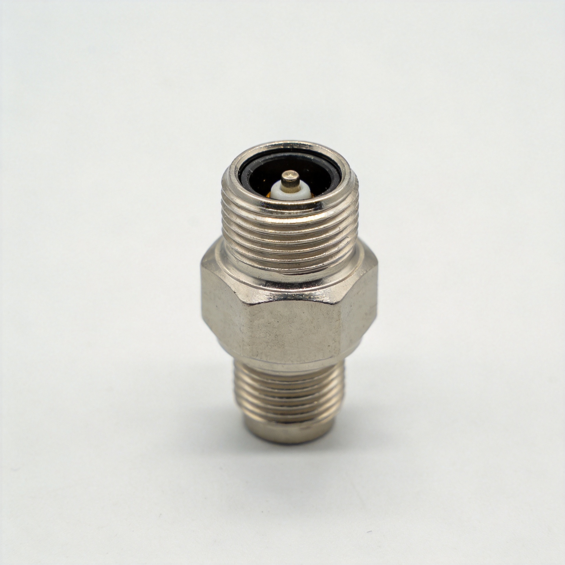
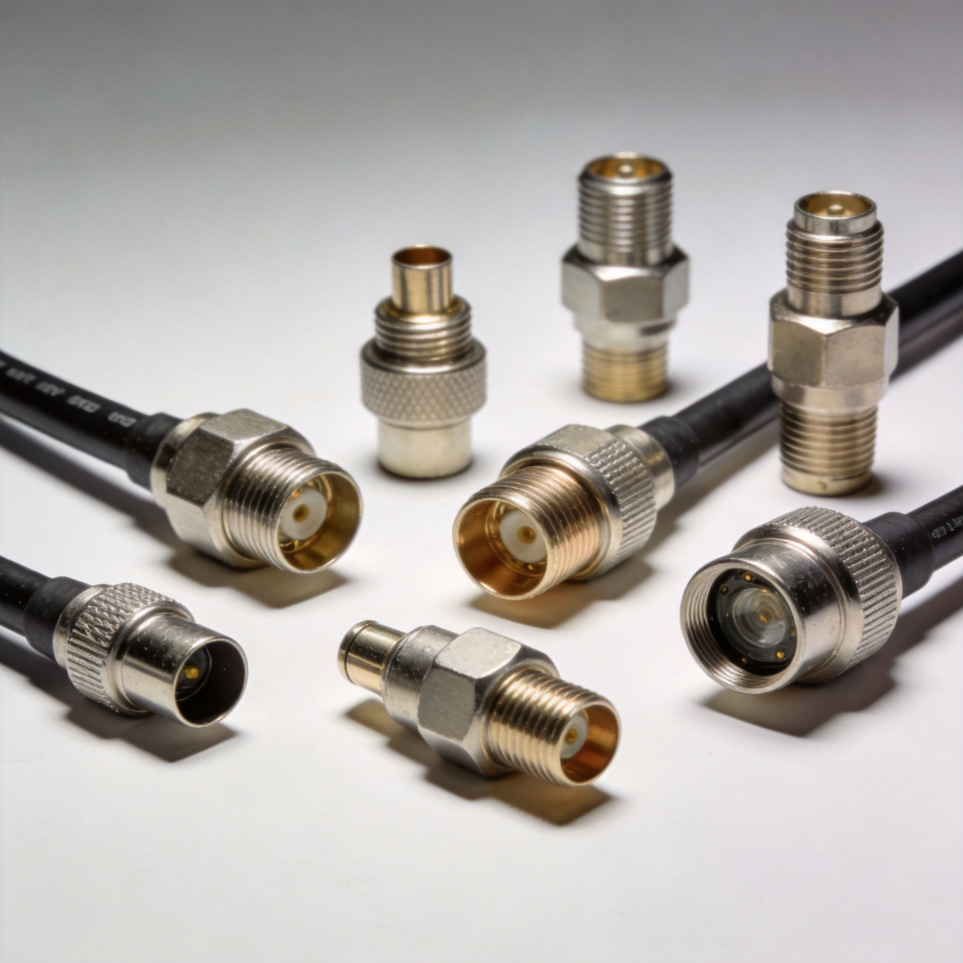
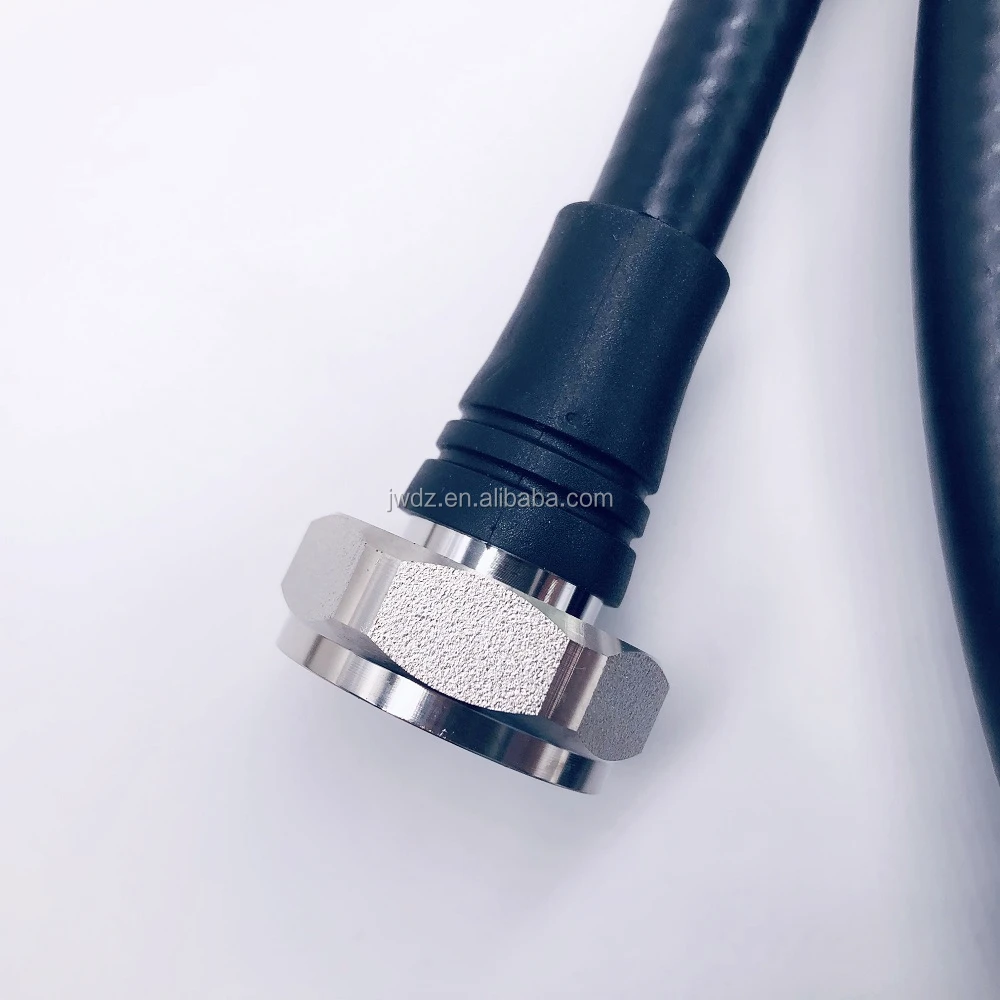
Connector compatibility must be checked before a purchase order is released. Identify the antenna interface, jumper interface, feeder connector, and radio-side connector, then confirm the complete mating path. An otherwise suitable antenna can create delay, adapter loss, or installation rework if the connector plan is not defined at the design stage.
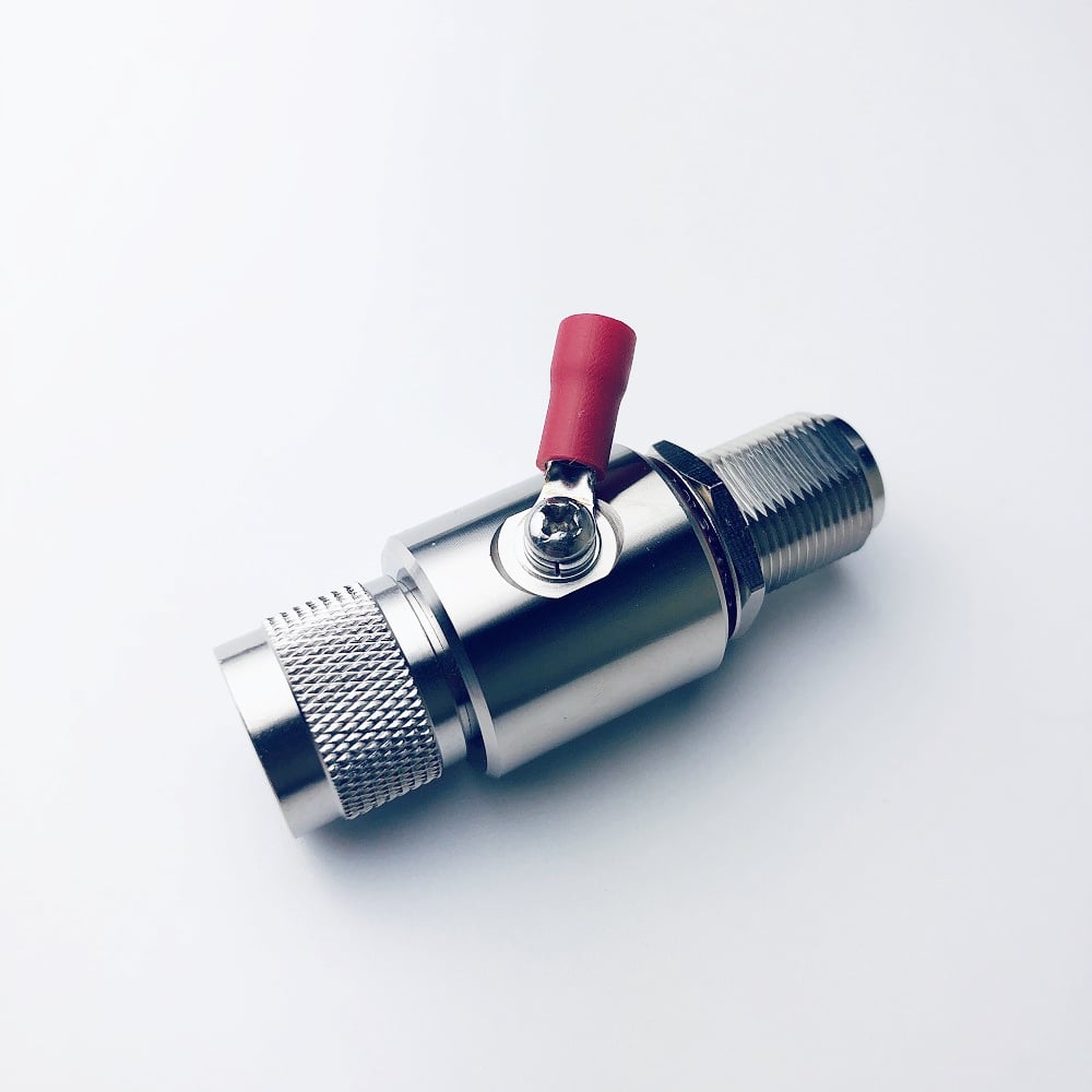
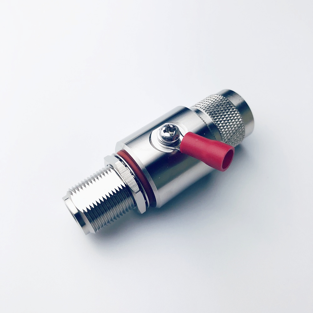
For example, the 380-6000MHz Low PIM Indoor Mimo Omni Antenna With N-Female Connector is a product option whose confirmed title and N-female interface make it relevant for buyers who need to compare a broad-band indoor MIMO omni form factor against their specified connector path. Verify all project-level electrical and mechanical requirements from the current product documentation before selection.
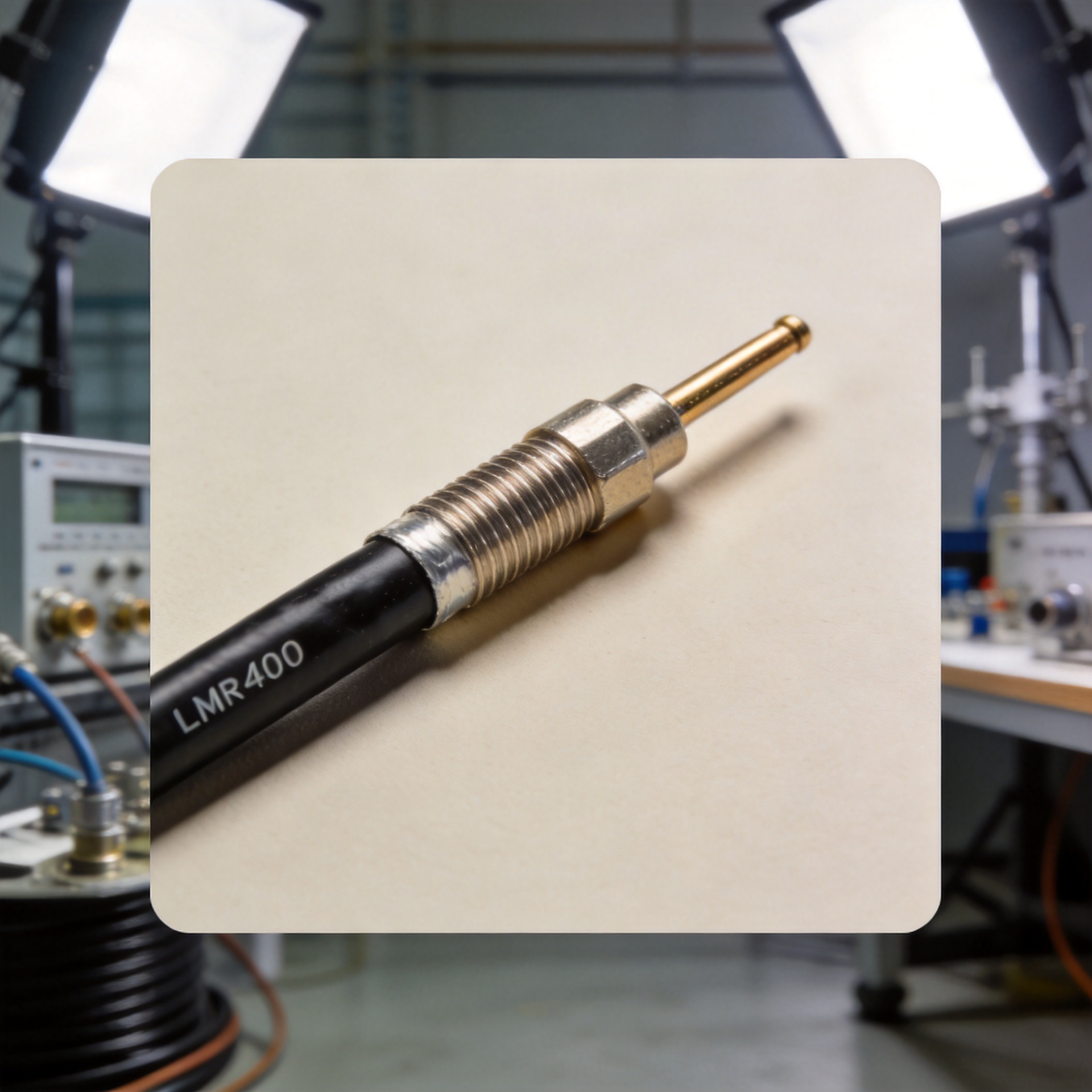
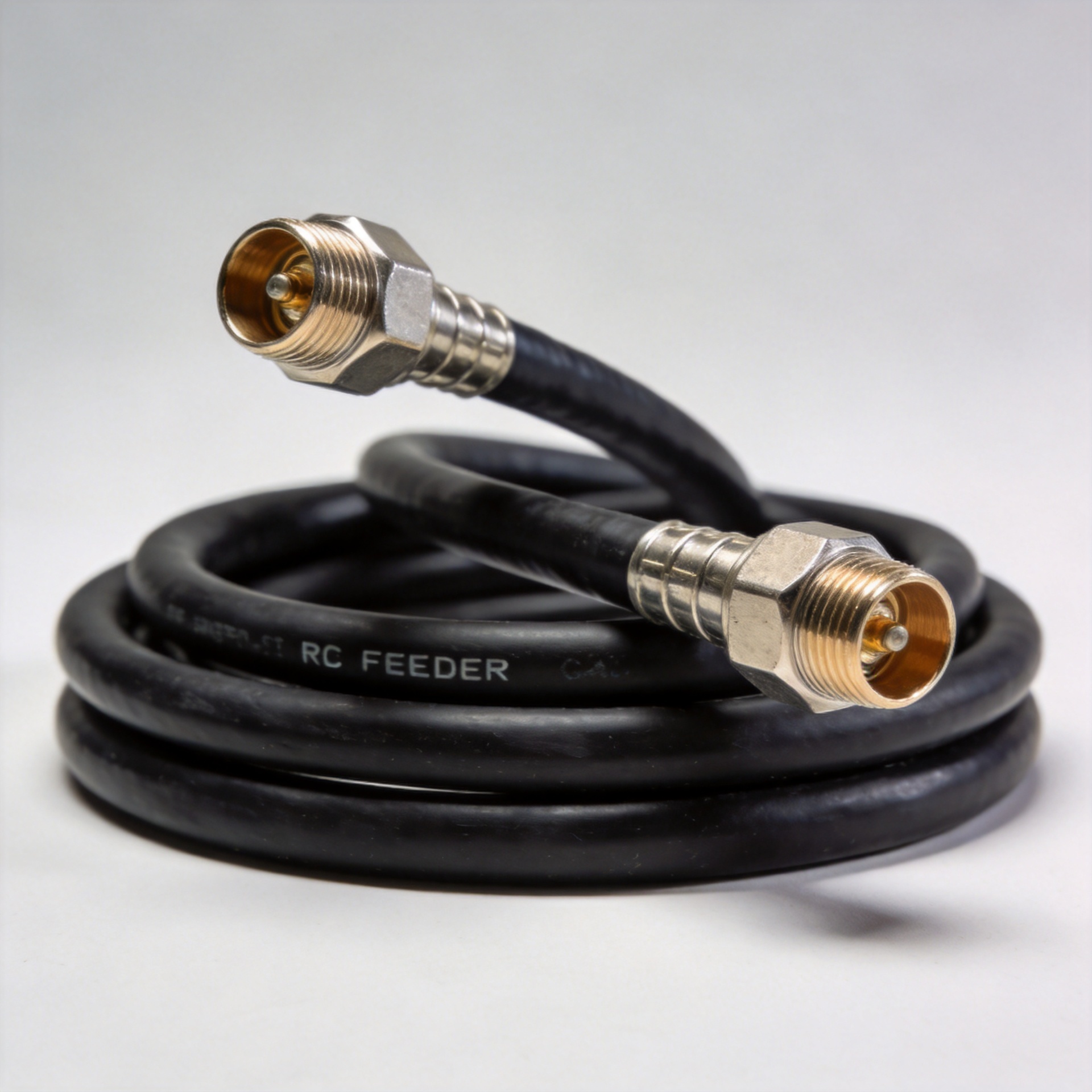
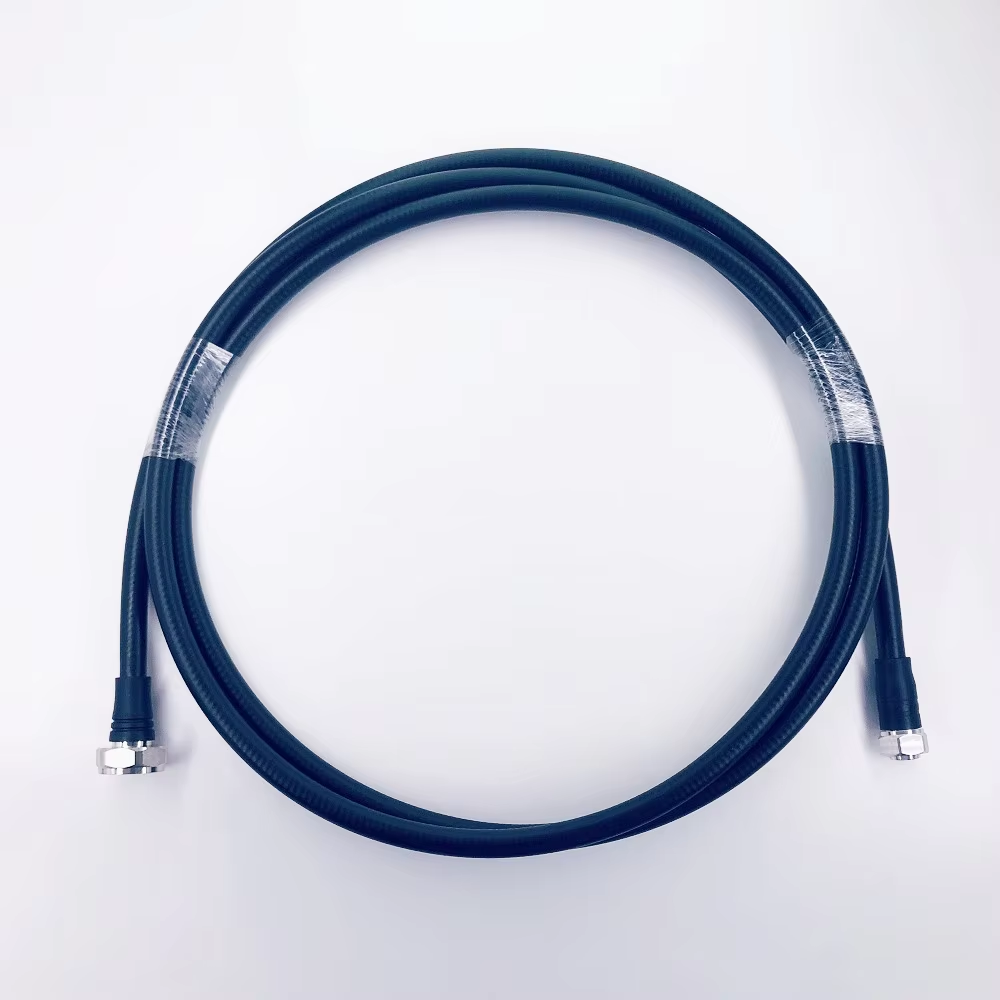
Feeder loss is equally important. Long cable runs reduce the signal available at the antenna, particularly as frequency increases. Include cable type, route length, connector count, and passive-device loss in the link budget. This is more useful than selecting an antenna in isolation and discovering later that the feed network consumes the expected margin.
Evaluate installation conditions, not just RF specifications
An indoor antenna must fit the ceiling type, mounting method, access constraints, and maintenance process. Confirm ceiling material and thickness, plenum or fire-safety requirements, cable bend space, visual requirements, and whether the antenna location remains clear of metal obstructions. In a multi-tenant building, coordinate with facilities teams before finalizing locations.
For a repeatable rollout, include labeling and acceptance testing in the procurement scope. Installers should be able to identify MIMO ports, preserve port mapping, inspect connector torque according to the applicable project procedure, and record the final antenna locations. These details help a network team troubleshoot coverage gaps after commissioning.
A practical indoor antenna MIMO 5G checklist
- List the live and planned 4G/5G frequency bands for the site.
- Confirm whether the radio and DAS design require 2x2 or 4x4 MIMO.
- Review polarization, port layout, isolation data, and intended radiation pattern.
- Match the antenna connector to the approved jumper and feeder interfaces.
- Calculate feeder, connector, splitter, and coupler losses in the link budget.
- Map each antenna location to room geometry, obstructions, and mounting constraints.
- Request current documentation and validate the installed system during commissioning.
Document the antenna mimo 5g requirement in the procurement record
For multi-site projects, use a controlled specification line to keep each antenna mimo 5g decision traceable across RF design, purchasing, and installation. Record the approved antenna mimo 5g band coverage, antenna mimo 5g port count, antenna mimo 5g polarization, antenna mimo 5g connector interface, antenna mimo 5g mounting type, and antenna mimo 5g feeder-loss budget. During review, compare antenna mimo 5g compatibility with the radio, then confirm antenna mimo 5g location against the site survey. A clear antenna mimo 5g record avoids substituting an antenna mimo 5g model simply because the physical format looks similar.
Before commissioning, verify antenna mimo 5g port mapping, antenna mimo 5g connector mating, antenna mimo 5g installation position, antenna mimo 5g cable labels, antenna mimo 5g clearance from obstructions, antenna mimo 5g acceptance-test results, antenna mimo 5g revision control, and antenna mimo 5g maintenance access. This antenna mimo 5g checklist supports consistent handover between contractors and network teams.
Make the decision with the whole DAS in view
A strong antenna mimo 5g choice is not a single catalog comparison. It is a documented match between band plan, MIMO architecture, polarization, connector path, coverage pattern, and installation reality. Use the checklist to compare technically suitable options, then let the site survey and RF design determine placement and final quantities. That approach gives procurement, installation, and network teams a common basis for indoor coverage decisions.