EN

How to Select a 30dB Attenuator for RF Test and Telecom Applications
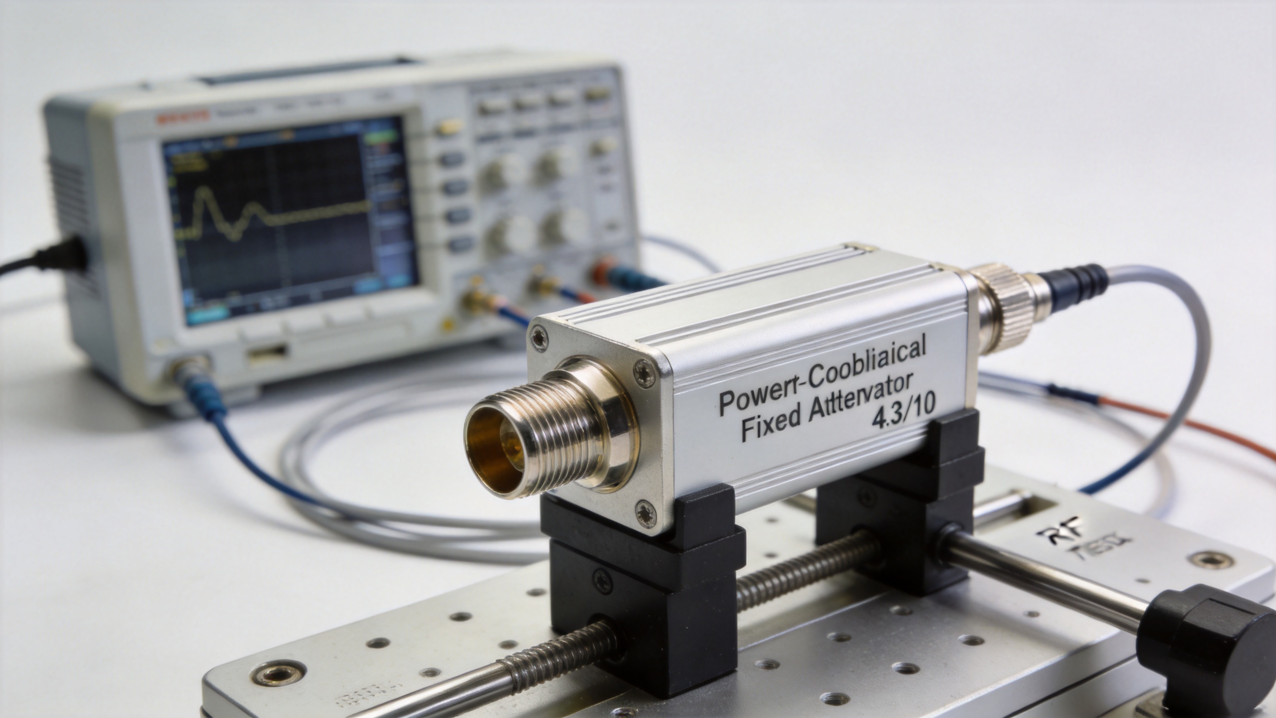
A 30db attenuator is often specified as if the number alone settles the choice. In RF test benches and telecom signal paths, it does not. The 30 dB value defines a nominal reduction, while frequency range, impedance, connector interfaces, power dissipation, VSWR, and installation conditions decide whether the part will behave predictably. This guide gives procurement and test engineers a practical way to compare a 30db attenuator before it is added to a cable assembly, instrument chain, or radio link.
Start with what 30 dB actually changes
A 30 dB reduction represents a 1000:1 power ratio. In an ideal matched system, a 10 W accepted input becomes approximately 10 mW at the output of a 30db attenuator. That output calculation is useful for protecting a spectrum analyser input or establishing a lower test level, but it must not be confused with the part’s thermal duty. Most of the accepted RF power is dissipated as heat inside the attenuator.
Write down the maximum continuous input, expected peak level, duty cycle, and fault condition before choosing a rating. A 30db attenuator installed after a power amplifier can see much more thermal stress than one used at the input of a receiver. If the source can be misconfigured or a transmitter can key up during testing, include that credible condition in the power budget.
Match the frequency range, impedance, and return-loss target
RF passive-component selection starts with the operating band rather than the centre frequency alone. Verify that the specified range of the 30db attenuator covers every planned measurement, including harmonics, calibration points, and future bands. Catalogue examples for 30 dB fixed units span from a few gigahertz to 18 GHz and beyond; the same attenuation value therefore says very little about high-frequency suitability.
For most test and telecom systems, select a 50 Ω 30db attenuator when the surrounding equipment is 50 Ω. Then review the stated VSWR or return loss across the full band, not only a typical value near the middle. An otherwise suitable attenuator with poor mismatch performance can affect level accuracy, increase reflections, and make a calibration result less repeatable. Where a system is 75 Ω, use a component designed for that impedance instead of assuming a 50 Ω device can be adapted without consequence.
Choose connectors as an electrical and mechanical requirement
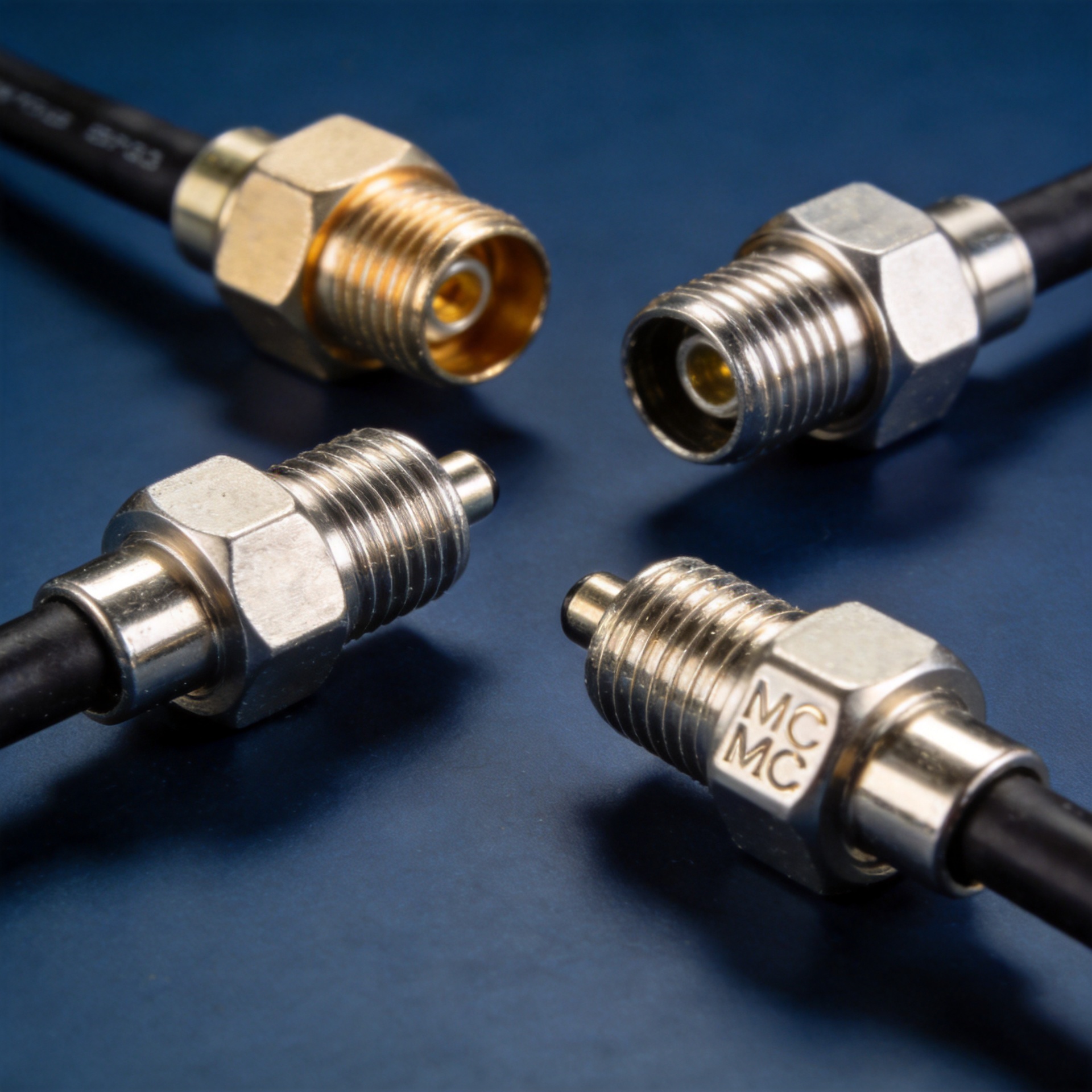
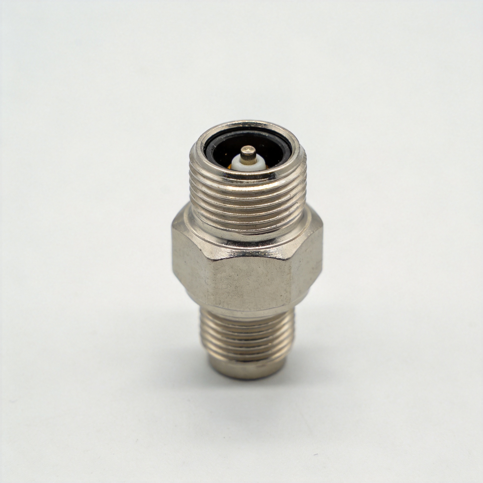
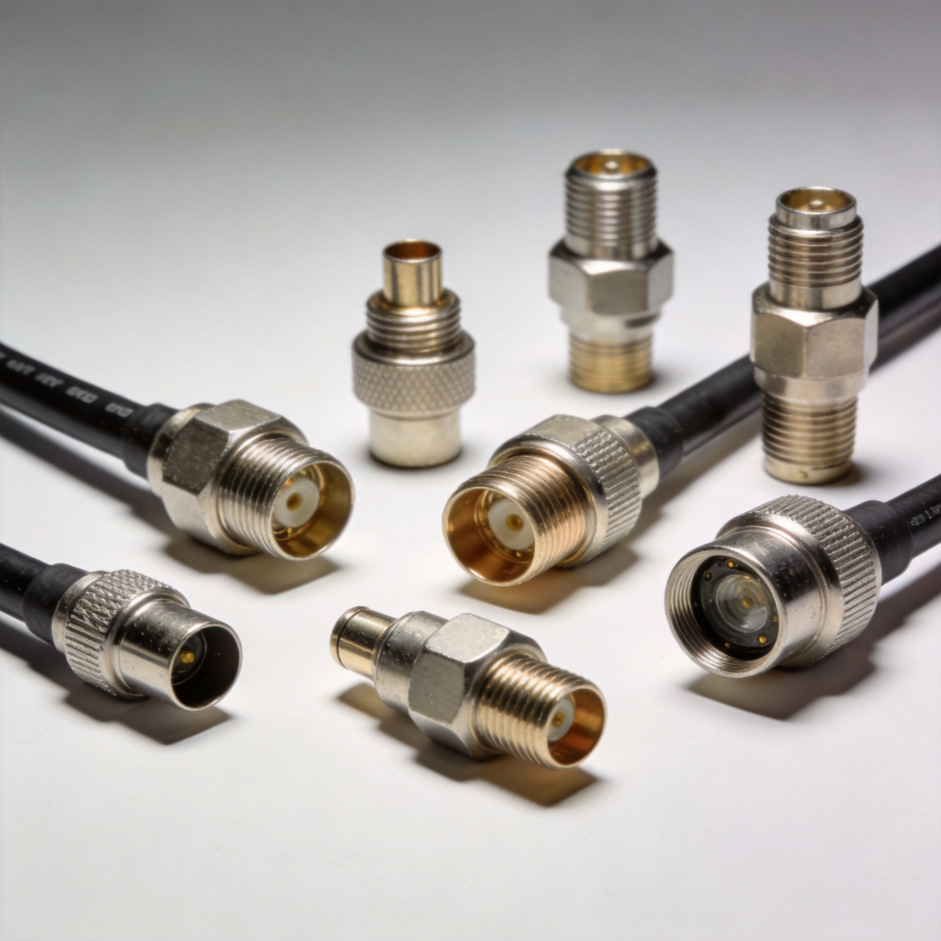
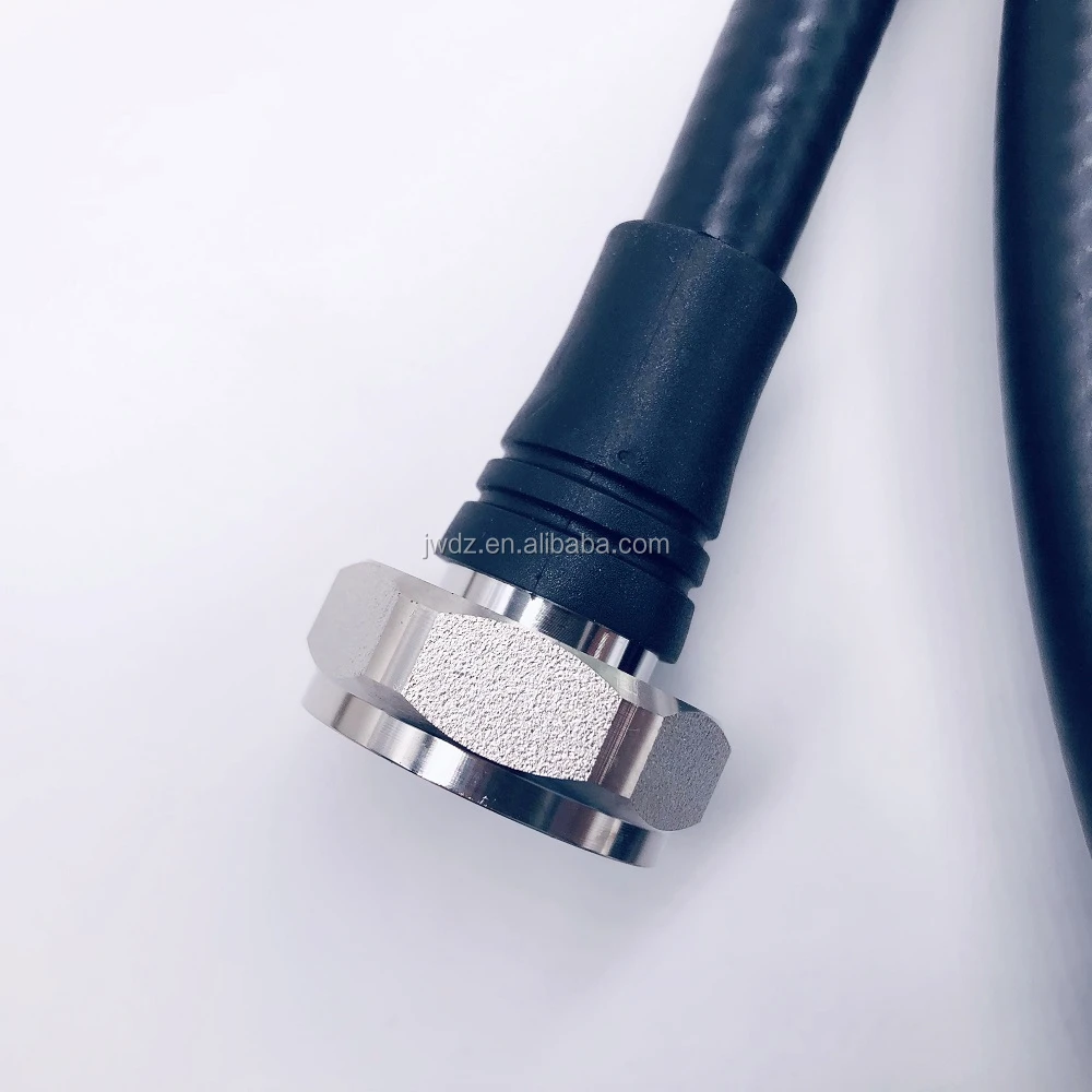
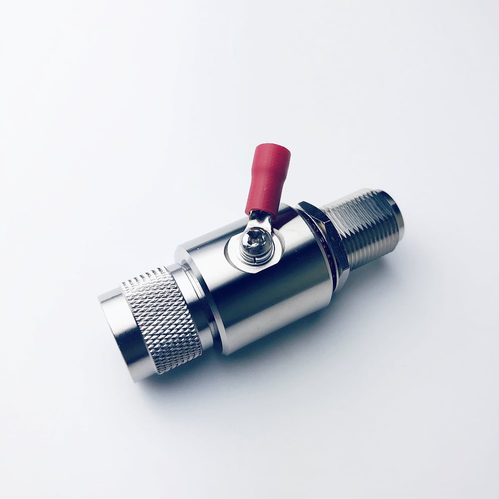
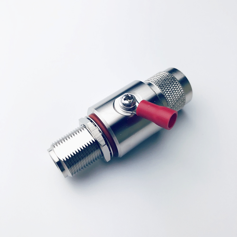
Connector selection is part of RF performance. SMA may be appropriate for compact laboratory paths within its rated frequency and mating-cycle limits; N, 4.3/10, 7/16, and other interfaces may better suit outdoor, higher-power, or telecom installations. Check the connector gender, interface standard, torque practice, cable-side connector, and clearance for the wrench before buying a 30db attenuator.
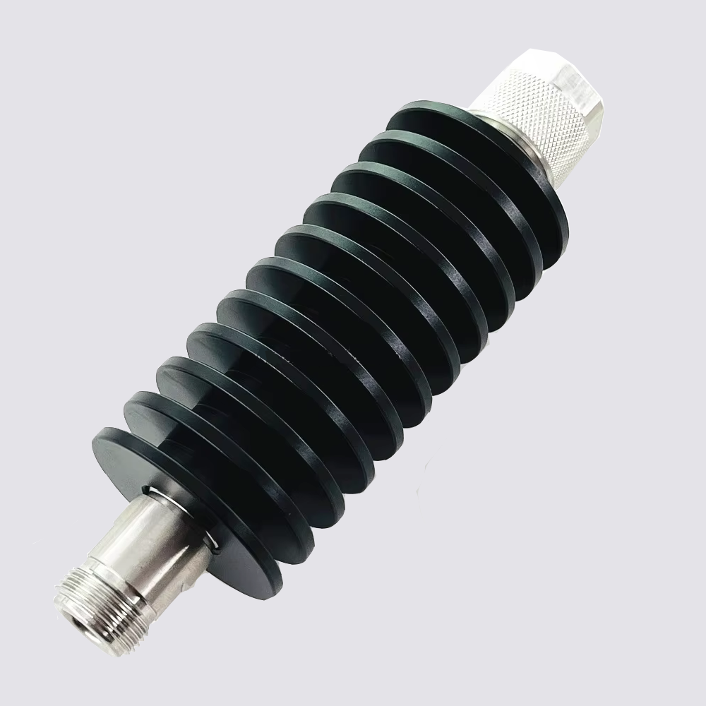
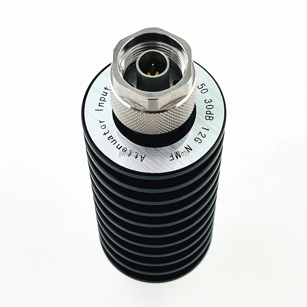
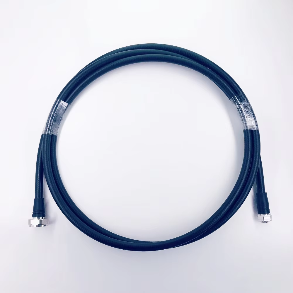
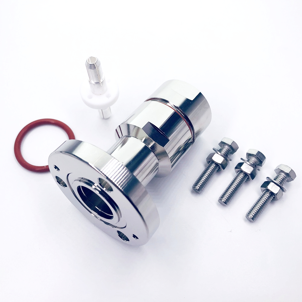
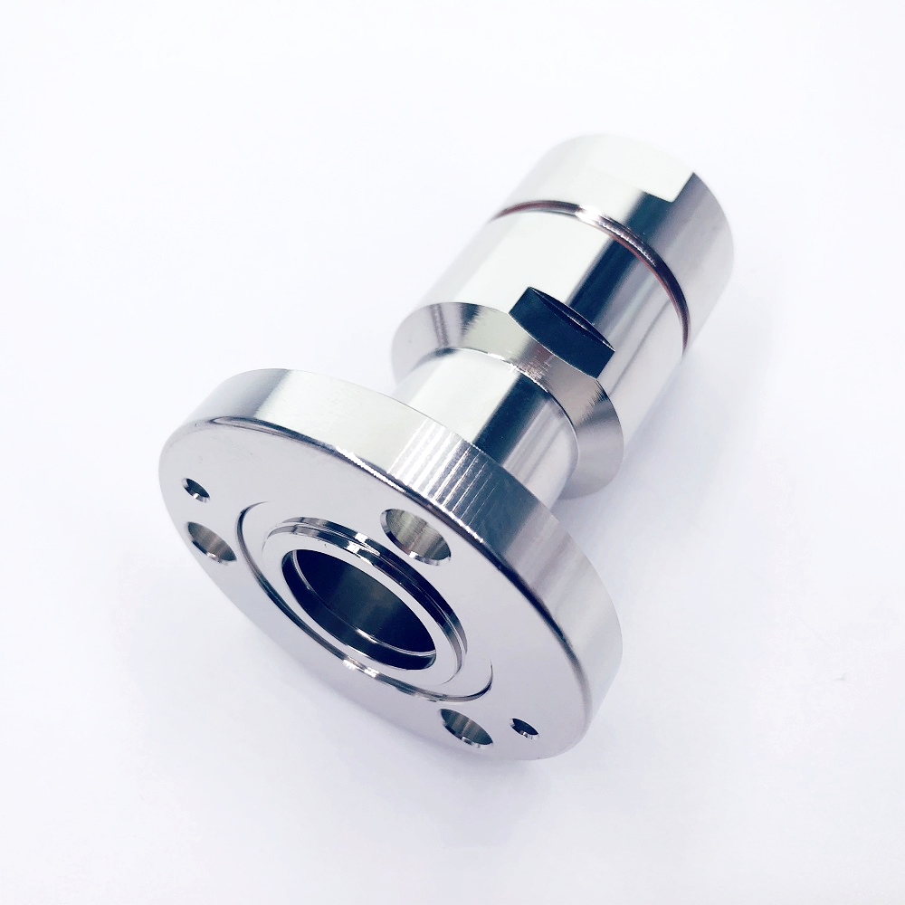
Do not select an adapter chain simply because the connectors physically mate. Every added transition can add uncertainty and possible mismatch. For applications requiring a higher-power coaxial interface, compare the actual connector and cooling arrangement with the expected site conditions. A listed product such as the 100W 20dB/30dB/40dB/50dB 3GHz/4GHz 4.3/10 attenuator can be reviewed against the required attenuation, interface, and band, with final suitability confirmed from the applicable datasheet.
Calculate thermal margin, then check the installed environment
Power rating is normally an input-power rating under stated ambient and mounting conditions. Read the derating curve for the candidate 30db attenuator. A rating at a controlled room temperature may not apply inside a sealed cabinet, beside a transmitter, or under direct sun. Heat-sink bodies, panel mounting, airflow, and cable routing all influence the temperature that the resistive element sees.
A sound comparison asks four questions: What continuous input power is accepted? What peak or pulsed power is permitted? At what ambient temperature does derating begin? What mounting surface or airflow did the manufacturer assume? For a high-power 30db attenuator, leave a usable thermal margin rather than designing exactly to the headline rating. Also prevent personnel contact with surfaces that may become hot during a long test.
Use a selection checklist for RF test work
- Define the attenuation objective: verify that 30 dB produces the required instrument input level with margin.
- Set the maximum accepted input: include normal, peak, and foreseeable fault power.
- Confirm band and impedance: check frequency coverage, 50 Ω or 75 Ω system impedance, and VSWR data at the band edges.
- Verify interfaces: match connector type, gender, torque requirements, cable construction, and environmental exposure.
- Review thermal conditions: use derating data for the actual cabinet, panel, or field environment.
- Plan verification: inspect connectors, measure loss and return loss where appropriate, and label the 30db attenuator in the test setup.
Separate bench requirements from telecom deployment needs
Bench use often prioritises low VSWR, repeatable connection geometry, and a frequency range that covers the instrument. Telecom deployment may place more weight on power handling, rugged connector interfaces, mounting, and sustained temperature. The suitable 30db attenuator is therefore the one whose published limits fit the whole RF path, not simply the one with the lowest price or the highest standalone power claim.
For sourcing, provide the supplier with the frequency band, system impedance, maximum continuous and peak input power, desired connector pair, mounting arrangement, ambient range, and quantity. This avoids a common procurement gap: selecting a 30 dB value first and discovering later that the interface or thermal envelope does not fit the application.
Final decision
Select a 30db attenuator by treating attenuation as one item in a linked specification. Confirm the power calculation, frequency and impedance match, connector compatibility, VSWR target, and thermal derating in that order. With those checks documented, RF test teams and telecom buyers can reduce measurement risk, protect downstream equipment, and make a more defensible component decision.