EN

Leaky Feeder vs Conventional Coaxial Cable for Tunnel Coverage
Tunnel radio design starts with a simple question that is easy to answer incorrectly: do you need to move RF energy from one point to another, or do you need usable wireless service all along the route? A leaky cable is built for the second job. Conventional coaxial cable is usually built for the first. Both may have a similar layered construction and both appear in RF systems, but their roles in an underground corridor are fundamentally different.
From an RF-system perspective, the right comparison is not “which cable is better?” It is “which signal path solves the coverage requirement without creating avoidable installation and maintenance work?” That distinction matters in rail tunnels, road tunnels, mines, utility passages, and underground facilities where walls, curves, equipment, and access restrictions make ordinary antenna placement difficult.
How a Leaky Cable Creates Tunnel Coverage
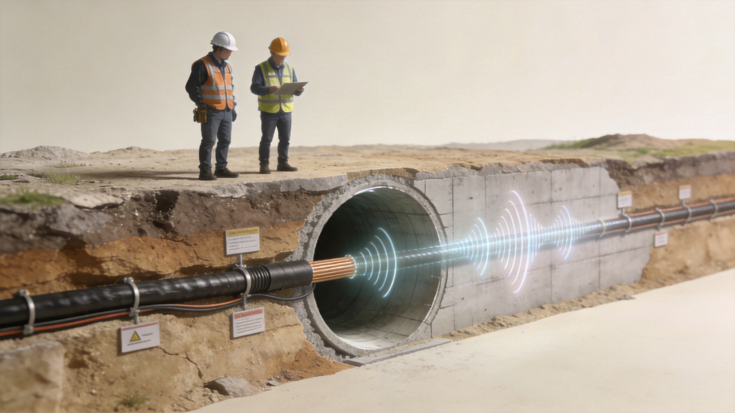
A leaky cable, also called a radiating cable or leaky feeder, is designed to couple RF energy between the cable and the surrounding space along its route. Its outer conductor uses controlled slots or coupling features, so the cable acts as a distributed antenna rather than a sealed transmission line. In a tunnel, that means two-way radio, cellular, data, or Wi-Fi signals can be available progressively along the cable path instead of being concentrated at a few antenna locations.
That continuous behavior is the key advantage of a tunnel radio leaky feeder. A tunnel is long and narrow, often curved, and usually rich in reflections. With a conventional antenna-only layout, a designer may need repeaters, remote units, antennas, feeder runs, brackets, power arrangements, and access plans at multiple points. A radiating route does not eliminate system engineering, but it can make the coverage geometry more predictable because the radiating element follows the corridor.
At its simplest, think of ordinary coax as a pipe that keeps the RF signal inside until it reaches an antenna. A leaky cable is closer to a controlled line of small radiating points. The complicating factor is that its distributed coupling also changes the loss budget: signal level must be reviewed over the full route, including cable attenuation, couplers, connectors, splices, and the intended service band.
Leaky Feeder vs Conventional Coaxial Cable: The Core Comparison
| Decision factor | Leaky feeder / radiating cable | Conventional coaxial cable |
|---|---|---|
| Primary function | Distributed RF coverage along the route. | Transfers RF energy between equipment, splitters, remote units, and antennas. |
| Radiation behavior | Intentionally radiates and receives along its length. | Designed to confine RF energy until a separate antenna or termination point. |
| Preferred tunnel use | Continuous communication zones where users or vehicles move through the corridor. | Backhaul, equipment interconnection, antenna feed runs, and short point-to-point sections. |
| Coverage layout | Follows the tunnel path and can reduce dependence on many discrete antennas. | Requires antennas or radiating elements at planned locations to create coverage. |
| Engineering priority | Route-level coupling, longitudinal loss, band performance, and coverage uniformity. | Insertion loss, impedance continuity, shielding, connector quality, and antenna placement. |
| Typical trade-off | Purpose-built coverage performance, with more application-specific design and installation discipline. | Efficient signal transport, but it does not create continuous RF coverage by itself. |
So, a conventional coax run is not a substitute for a leaky cable when the project requirement is continuous in-tunnel service. Conversely, a radiating cable is not automatically the right choice for every RF connection. It should not be used merely because the system contains a tunnel; a point-to-point equipment link may still call for ordinary low-loss coax.
Where Conventional Coaxial Cable Still Belongs
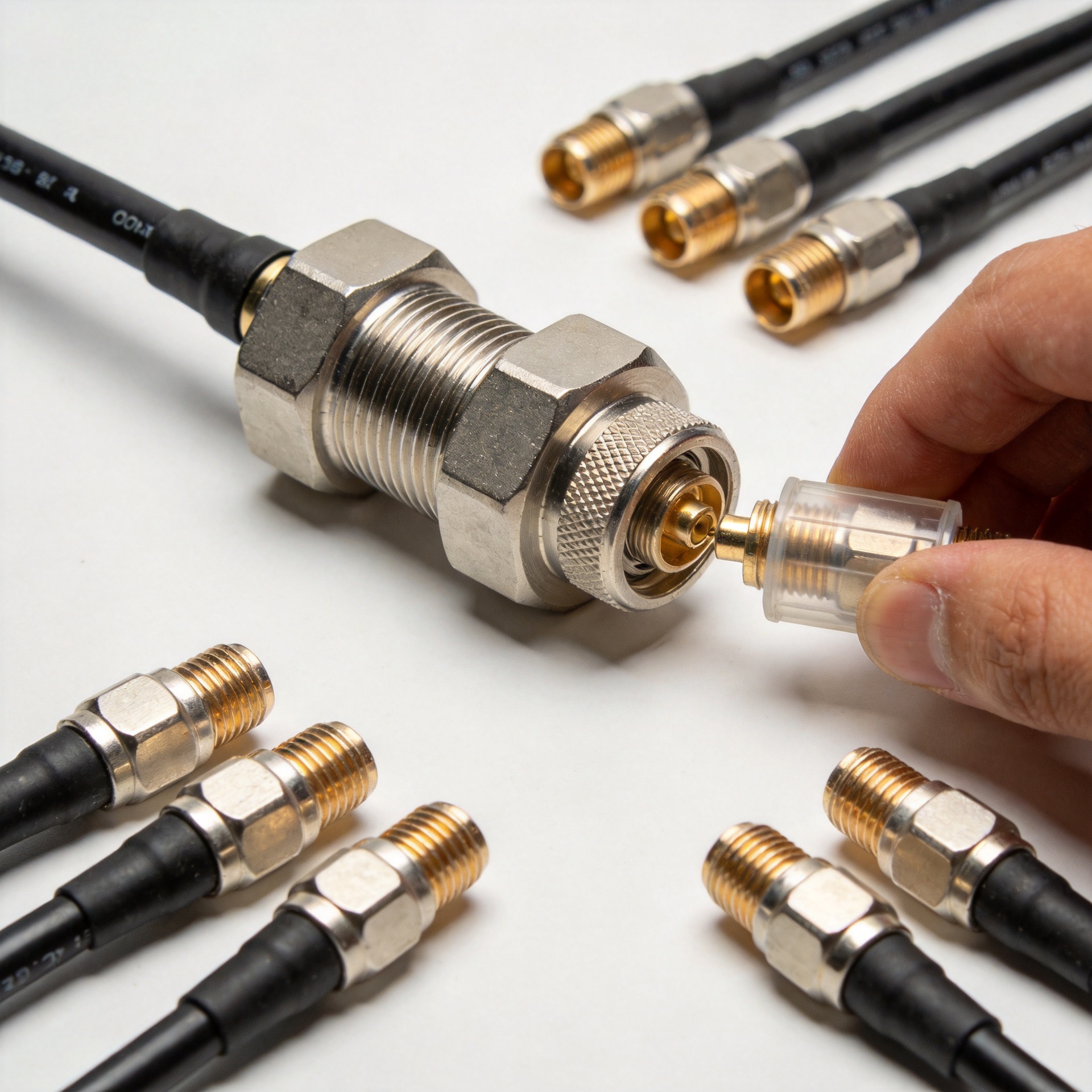
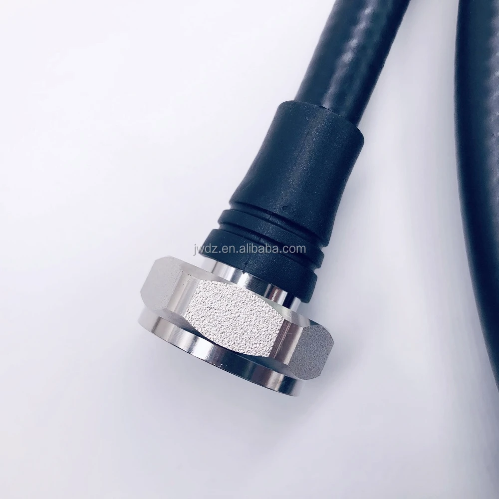
Conventional coaxial cable remains essential in most tunnel communication architectures. It commonly connects the base station, repeater, bi-directional amplifier, remote radio, splitter, or coupling equipment to the radiating section. It is also appropriate where the cable is expected to carry a signal between fixed points without intentionally serving nearby users.
This is where a project can go wrong by treating the two cable types as competing parts instead of complementary ones. A practical design may use conventional coax in equipment rooms and feeder branches, then transition to a tunnel radio leaky feeder along the coverage corridor. The boundary should be defined by the coverage plan and link budget, not by a preference for one catalog category.
Installation Path: Why Routing Details Change the Decision
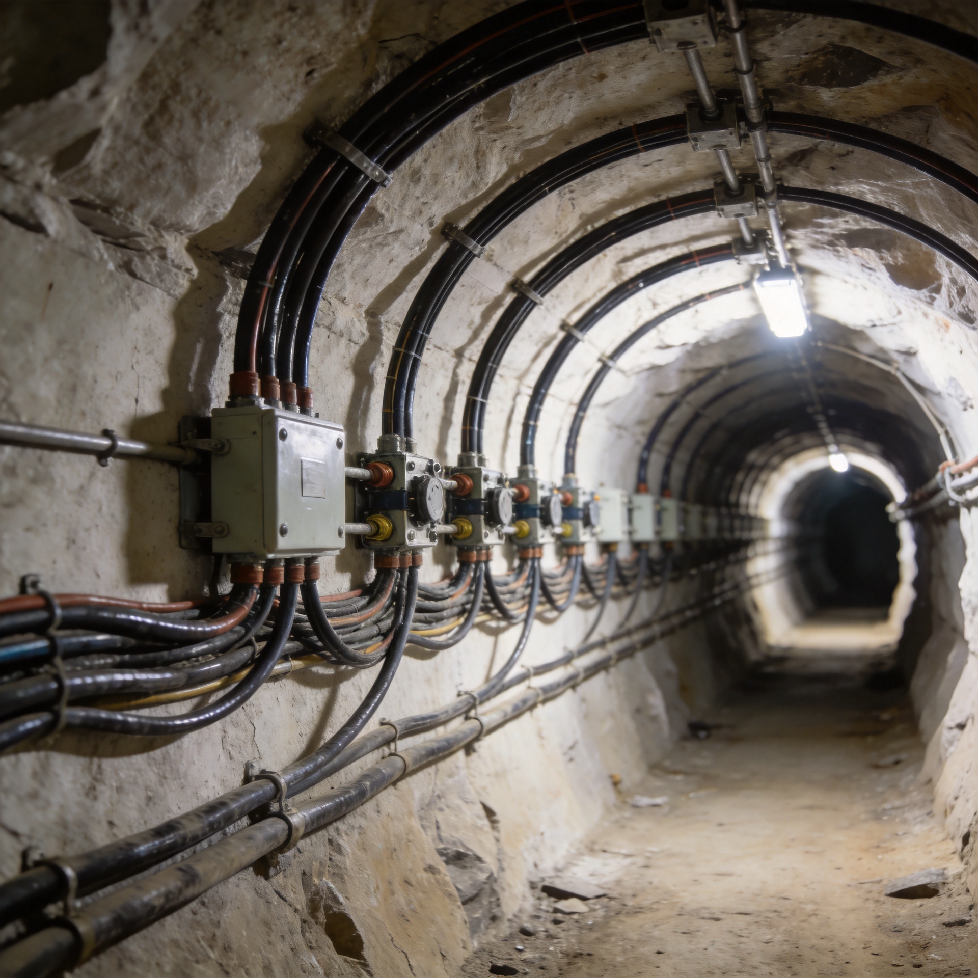
In a tunnel, routing constraints are not a minor detail. Ceiling profiles, cable trays, emergency walkways, ventilation equipment, drainage, vehicle clearance, and maintenance access can all affect cable placement. When a tight bend or constrained turn is present, the allowed bend radius becomes a design input rather than a late-stage installation note. Respect the manufacturer’s stated minimum bend radius and support spacing; forcing a cable around a corner can damage the structure that supports its electrical performance.
A useful field rule is this: the route that looks shortest on a drawing may not be the route that produces the most stable coverage. The chosen leaky cable position should be reviewed for line-of-sight conditions, obstructions, expected user height, service-band behavior, and access for inspection. At the same time, every connector and splice should be treated as part of the RF budget, not just as a mechanical join.
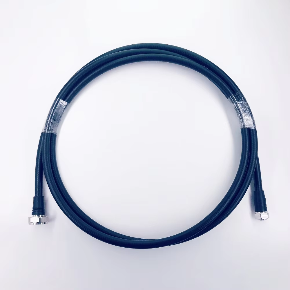
For projects that need a product reference during specification review, the verified product page for High Quality 75 Ohm 75-10 Slywv Leaky Feeder Cable for Tunnel, Mine Communication can be used as a starting point for a technical inquiry. Confirm the final impedance, frequency range, cable size, fire-performance requirements, connectors, and project-specific installation conditions with the supplier before purchase.
Leaky Cable Specification Questions That Prevent Rework
Before approving a leaky cable, ask which service bands the leaky cable must support, where the leaky cable route begins and ends, and how each leaky cable section will be coupled and terminated. A leaky cable layout should also show branches, cross-passages, equipment interfaces, and planned test points.
For procurement, compare each leaky cable by its applicable frequency range, attenuation data, coupling behavior, impedance, jacket construction, and installation limits. The right leaky cable is the one whose published characteristics match the system design. A leaky cable should not be selected solely because its diameter looks similar to a standard feeder cable.
For installers, protect the leaky cable during pulling, support the leaky cable at the specified intervals, and preserve the required bend radius at every turn. After installation, test the leaky cable route as a system. A visual check cannot confirm whether a leaky cable connection, splice, or bend has affected RF performance.
For operations teams, document the leaky cable path and keep spare parts compatible with the installed leaky cable system. If continuous service is the objective, validate the tunnel radio leaky feeder at representative points along the route. The tunnel radio leaky feeder should be assessed at curves, portals, junctions, and other locations where the radio environment changes. That route-level validation is what turns a tunnel radio leaky feeder from a component choice into a dependable coverage solution.
A Practical Selection Checklist for Tunnel Communication
- Define the service objective. Is the system transporting RF between devices, or delivering radio coverage continuously along the tunnel?
- Map the route. Include tunnel length, curves, branches, cross-passages, equipment rooms, and restricted installation areas.
- Build the link budget. Review source power, cable loss, couplers, connector losses, end termination, and the required received level throughout the route.
- Check the operating bands. A leaky cable must be selected for the actual technologies and frequency ranges in the project, not for a generic “tunnel cable” label.
- Specify the mechanical environment. Confirm bend radius, mounting method, vibration, moisture, dust, temperature, flame or smoke requirements, and access for maintenance.
- Plan testing before handover. Document cable routing and connection points, then verify RF performance and coverage after installation rather than relying on visual inspection alone.
Choosing the Right Cable for the Job
Both options are valid—the right answer depends on whether you are optimizing for distributed coverage or controlled signal transport. If workers, passengers, emergency teams, or connected equipment need service throughout a tunnel, a leaky cable system is typically the more direct design approach. If the task is to connect a radio source to a remote device or antenna, conventional coaxial cable is usually the better fit.
For many tunnel projects, the strongest design uses both: conventional coaxial cable for equipment interconnection and a tunnel radio leaky feeder for the long coverage path. Start with the coverage requirement, validate the full RF and mechanical specification, and choose the cable architecture that matches the real operating environment—not just the product name.