EN
EN

LMR400 Cable Loss: How to Compare Alternatives for RF Runs
When an RF run is short, almost any correctly specified 50-ohm coax may appear to work. Once the route gets longer, the operating frequency rises, or the receiver margin narrows, lmr400 cable loss becomes a design decision rather than a catalogue detail. The useful question is not simply “Which cable has the lowest number?” It is which cable gives the required attenuation, mechanical handling, jacket performance, connector compatibility, and installed reliability for the route you actually have.
For telecom equipment builders, antenna-system integrators, labs, and OEM teams, a sound comparison starts with the whole RF path. This article provides a practical framework for comparing flexible LMR-400-style coax, ultra-flexible alternatives, and larger feeder-style cables without treating any single loss value as universal.
Start the Comparison With the Real RF Run
LMR400 cable loss must be read at the system frequency and multiplied by the installed route length. Attenuation rises with frequency, so a value that is acceptable at a lower-band test frequency may consume a meaningful portion of the link budget at multi-gigahertz operation. Search results for LMR-400 listings illustrate the difference: one listing reports 4.25 dB at 1 GHz, while another reports 10.8 dB per 100 ft at 5.8 GHz. Those figures are examples, not interchangeable design data; use the data sheet for the exact cable construction and the frequency you will use.
A practical starting calculation is:
Total cable attenuation (dB) = published attenuation per unit length × installed length
Then add the losses that are often omitted from an early estimate: connector pairs, adapters, lightning protection devices, jumpers, and any transition from flexible coax to feeder. For a short run, connector quality and workmanship may matter as much as the cable. For a long run, the cable attenuation usually becomes the dominant term.
Compare LMR-400-Style Cable by Frequency, Length, and Margin
The first comparison column should be lmr400 cable loss at the intended frequency—not a marketing description such as “low loss.” Ask each supplier for attenuation at the same frequency units and the same length units. Convert everything to dB per metre or dB per 100 m before ranking options.
| Decision factor | Why it matters | What to verify |
|---|---|---|
| Attenuation | Sets the RF cable loss budget | Data-sheet value at your operating frequency and route length |
| Diameter | Larger conductors and dielectric structures can lower loss | Space, tray fill, gland size, and routing clearance |
| Flexibility | Controls installation effort and repeated-bend suitability | Minimum bend radius and flex-cycle requirements |
| Power handling | Limits safe transmitted power and temperature rise | Rated power at frequency and ambient conditions |
| Jacket construction | Determines environmental and fire-performance suitability | UV, indoor/outdoor, flame-retardant, or halogen-free requirements |
Using this table avoids a common mistake: choosing the lowest lmr400 cable loss figure even when the cable cannot make the bends, fit the pathway, or meet the installation specification. A slightly higher-loss flexible cable can be the better installed solution if it eliminates stressed bends, extra adapters, or unsuitable jacket material.
When a Larger Feeder Cable Is the Better Alternative
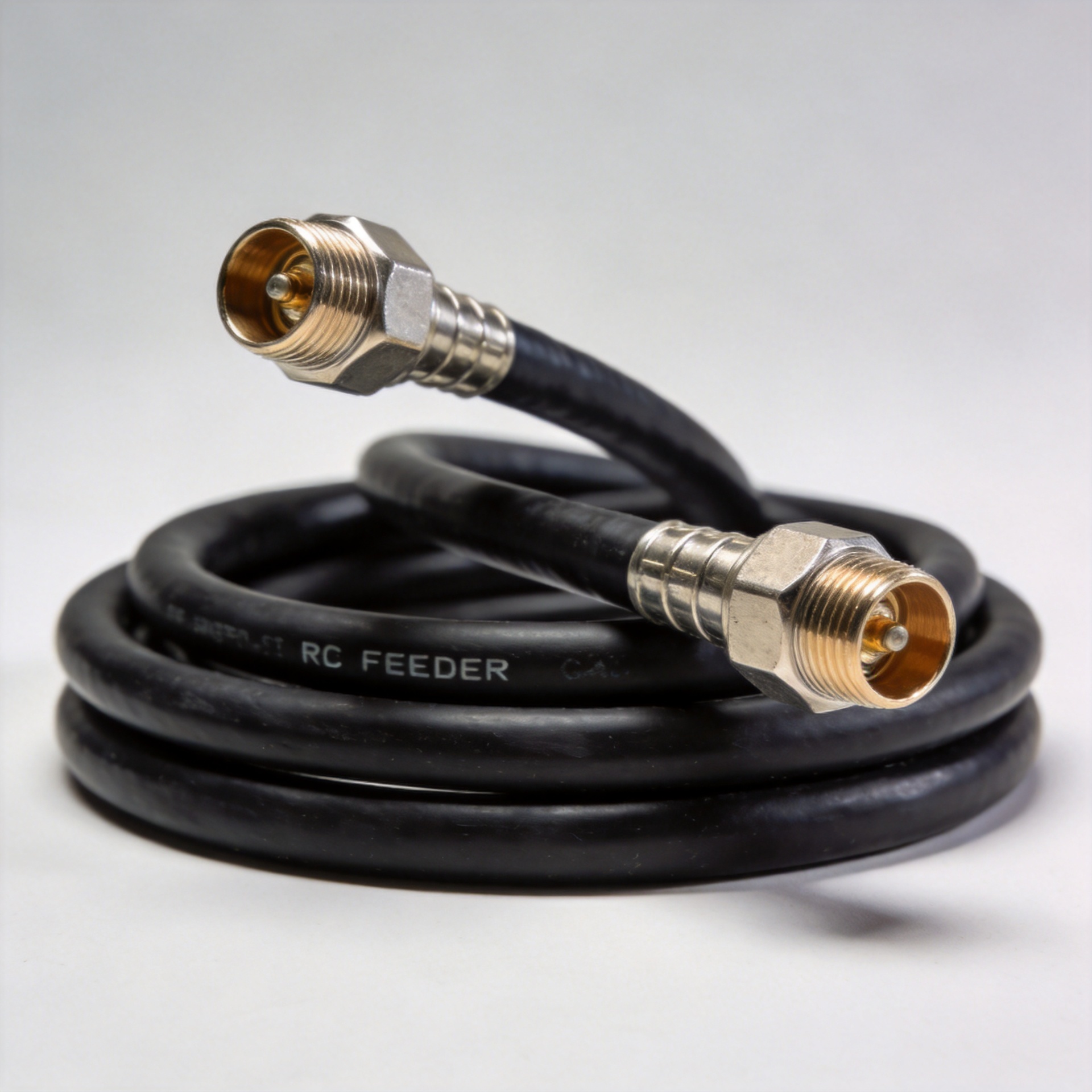
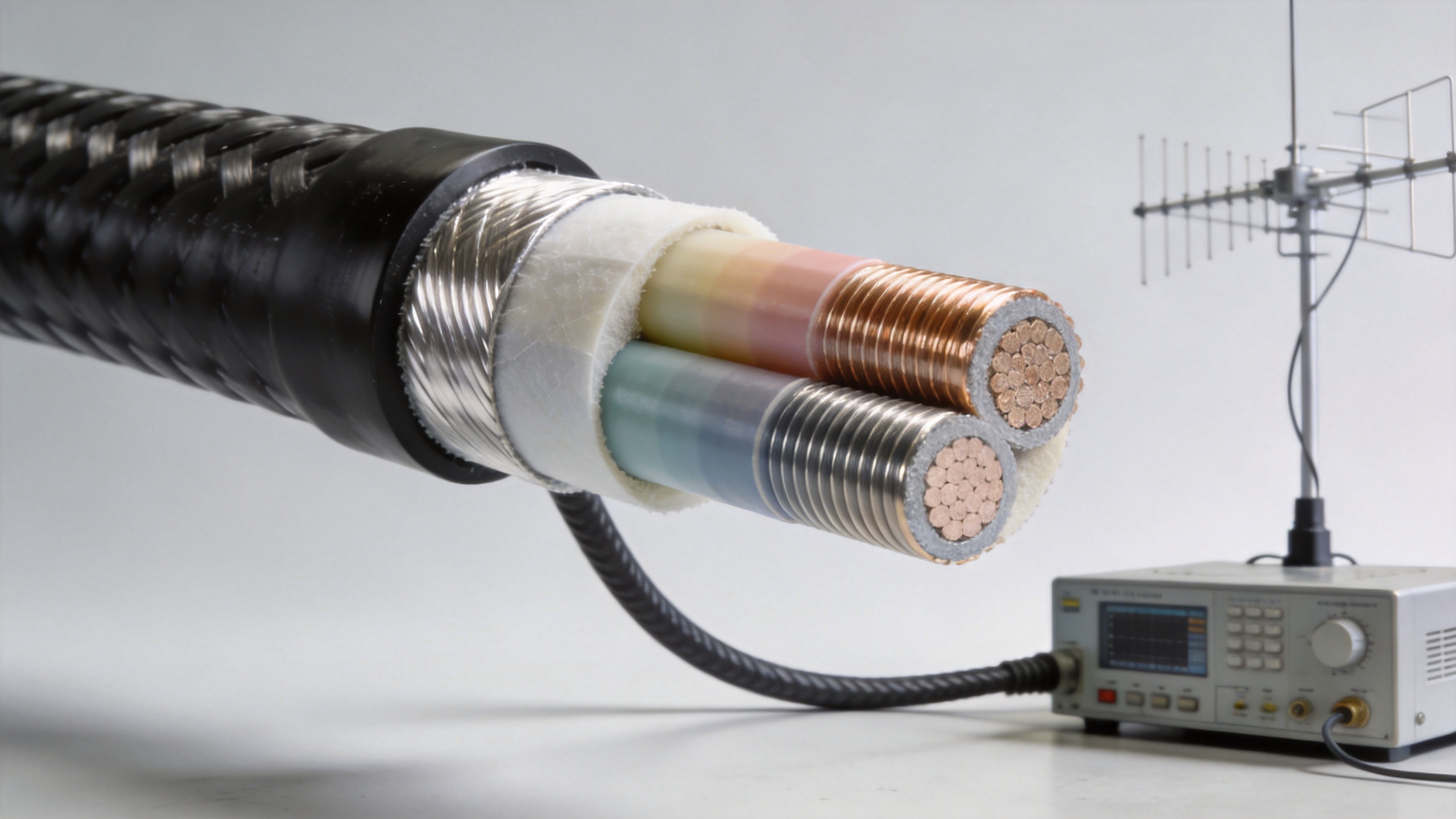
If the calculation shows that lmr400 cable loss leaves too little receive margin, move up in diameter before trying to recover the budget with higher transmit power. Larger feeder or hardline-style cable commonly reduces attenuation per metre, making it attractive for long antenna feeders, distributed systems, and higher-frequency links. The trade-off is mechanical: larger cable is heavier, less flexible, and more demanding at bends, entries, supports, and terminations.
Use a larger feeder option when the route is long and stable, the pathway is planned, and low attenuation has more value than easy field handling. Keep a shorter flexible jumper where equipment movement, service access, or a tight bend is unavoidable. This hybrid approach can reduce total lmr400 cable loss-related risk while preserving serviceability at the equipment end.
When an Ultra-Flexible Alternative Makes Sense
Ultra-flexible coax is designed for routes with tighter bends or more frequent movement. It can simplify cabinet routing, test setups, and antenna assemblies, but flexibility usually changes the construction and may change attenuation. Do not assume an ultra-flexible product has identical lmr400 cable loss to a standard flexible construction simply because the nominal size is similar.
Compare the alternative at the exact frequency, then evaluate the installed result. A cable that needs fewer sharp turns, fewer couplers, and less rework may protect the actual rf cable loss budget better than a nominally lower-loss option installed under mechanical stress. Confirm the minimum bend radius in both static and repeated-flex conditions.
Make Jacket and Fire Performance Part of the RF Decision
Attenuation is only one part of a dependable feeder selection. Indoor routes, tunnels, public buildings, and equipment rooms may need flame-retardant or halogen-free jacket requirements. Selection guides commonly reference tests such as IEC 60332-1 for flame propagation and IEC 60754-1/-2 for halogen-related performance; confirm which standards apply to the project and whether the exact cable version is qualified.
For an option intended for structured RF installations, review the 1/2-inch low-loss flexible cable with flame-retardant halogen-free jacket as a product-category reference. The product title identifies its low-loss flexible construction and jacket type; obtain the applicable data sheet before assigning attenuation, power, or compliance values to a design.
A Five-Step Procurement Checklist
- Define the highest operating frequency, route length, impedance, and allowable total loss.
- Calculate lmr400 cable loss using the exact cable data sheet, then add connectors and passive devices.
- Compare standard flexible, ultra-flexible, and larger feeder options in one common attenuation unit.
- Check bend radius, connector interfaces, pulling method, environmental exposure, and jacket/fire requirements.
- Request samples or assemblies when the route has tight bends, high power, outdoor exposure, or repeatable production requirements.
The Bottom Line
The most suitable alternative is rarely selected on attenuation alone. Use lmr400 cable loss as the first filter, then judge the complete installed path: frequency, length, connectors, power, bends, jacket, and maintenance access. For long, fixed runs, a larger feeder can improve margin. For constrained routes, flexible or ultra-flexible coax can reduce installation risk. A documented comparison based on the exact route gives purchasing and engineering teams a more reliable RF outcome than choosing by cable name alone.