EN
EN

UFL to SMA Connectors: What to Verify Before Integration
A ufl to sma connector assembly looks simple: a compact board-side interface, a short coax lead, and a threaded SMA connection for an external antenna or test point. In an RF system, however, the assembly is part of the signal path—not an accessory. Before releasing a design or ordering a cable batch, verify the interface family, polarity, cable construction, clearance, and RF limits as one system.
As an RF systems engineer, I start with the complete path from the radio module to the antenna. I used to evaluate each component only from its own datasheet—until it became clear that the weakest transition, rather than the strongest individual part, determines the usable result. This is especially relevant when a delicate U.FL board connector feeds a robust, panel-mounted SMA interface.
Start with the actual interfaces, not the listing name
“UFL,” “U.FL,” “IPEX,” “IPX,” and “MHF” are often used loosely in product listings. They are not a substitute for confirming the mating interface on the PCB. Identify the connector family and the exact board receptacle part number before selecting a ufl to sma connector cable. A visually similar micro-coax plug may not mate correctly, and forcing it can damage the board receptacle.
At the SMA end, verify every part of the interface definition:
- Gender: determine whether the equipment expects an SMA jack or plug.
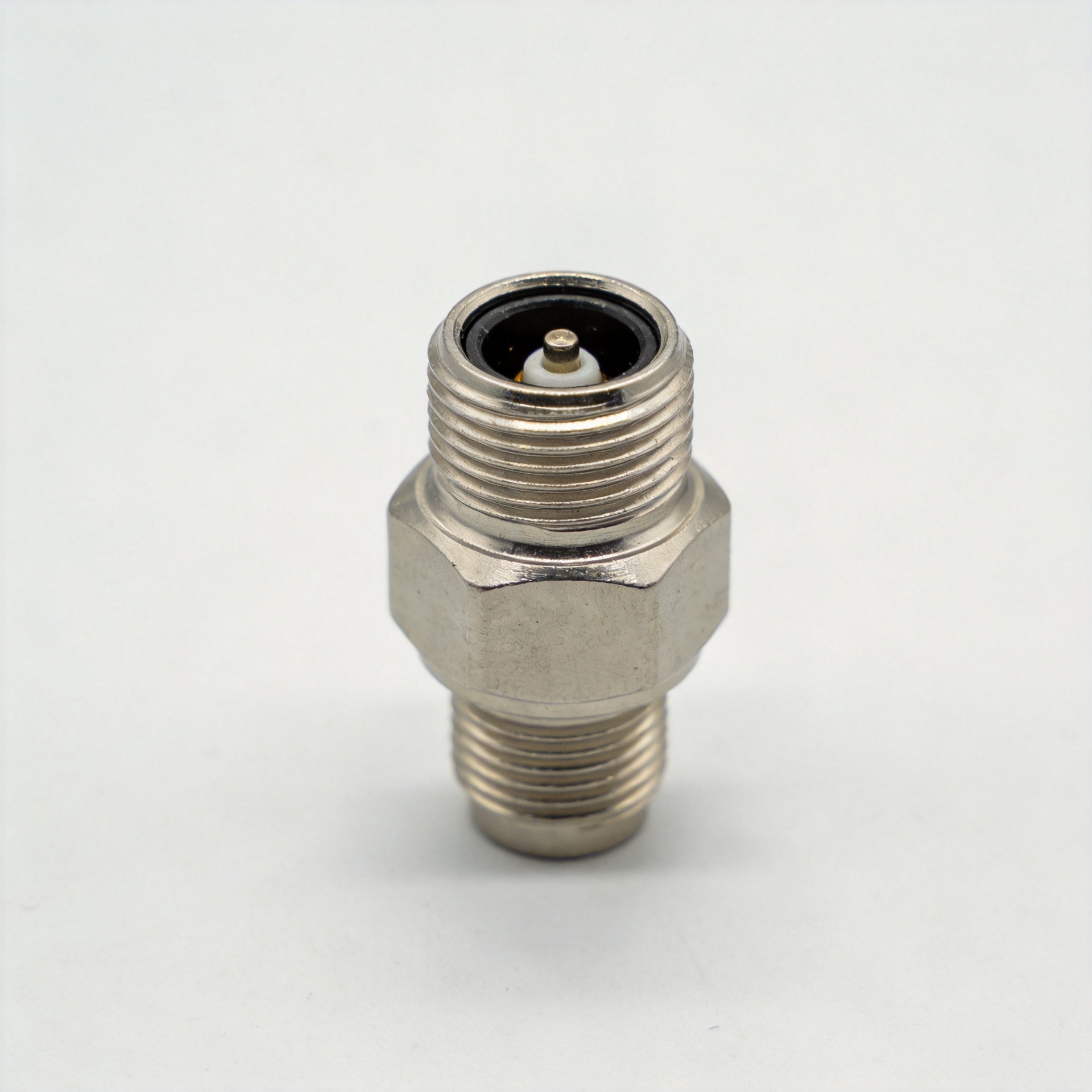
- Polarity: distinguish standard SMA from RP-SMA; the thread style alone does not confirm the center-contact arrangement.
- Mounting method: choose bulkhead, edge-mount, or free-hanging SMA according to the enclosure and antenna location.
- Mechanical stack-up: check panel thickness, thread length, washer arrangement, and nut access before release.
A sma to sma connector cable may use a familiar threaded interface at both ends, but it does not solve the board-side compatibility question. The U.FL end must be validated independently.
Confirm a continuous 50-ohm RF path
Most U.FL-to-SMA assemblies are intended for 50-ohm systems, but “50 ohm” should be treated as a whole-path requirement. Confirm the module output, PCB launch, U.FL receptacle, micro-coax cable, SMA connector, and antenna or instrument input are specified for the same impedance. The connector label is not enough if the cable or board transition is unsuitable for the operating band.
Frequency capability also belongs to the complete assembly. Standard SMA products are commonly used in 50-ohm RF paths, while the allowable frequency of a finished ufl to sma connector cable depends on the exact connector versions, cable diameter, cable length, and test conditions. Request the supplier’s assembly-level frequency range, VSWR or return-loss information, and insertion-loss data at the frequencies that matter to your application. A short Wi-Fi lead, a GNSS pigtail, and a higher-frequency radio link should not be qualified by the same assumption.
If the specification says only “SMA,” ask for the part number and performance limits. That small clarification can prevent an impedance or bandwidth mismatch from entering the BOM.
Choose cable construction for the route, not only for length
The cable between U.FL and SMA is often the dominant integration compromise. Very small micro-coax is flexible and easy to route in compact electronics, yet its loss usually rises with frequency and length. A thicker cable can improve mechanical robustness or RF performance, but may overload a small U.FL receptacle if it is bent or pulled improperly.
Check these items before choosing a ufl to sma connector assembly:
- Finished length: use the shortest practical route, while leaving enough service loop for assembly and inspection.
- Minimum bend radius: compare the cable requirement with the actual enclosure corners and cable exits.
- Strain relief: make sure pulling force is carried by the cable routing or SMA bulkhead, not by the U.FL receptacle.
- Shielding and jacket: review the installation environment, nearby digital noise sources, abrasion points, temperature, and vibration.
- Connector orientation: select straight or right-angle SMA orientation so that the antenna lead does not create a side load after installation.
For a multi-site program, standardizing a single cable configuration is different from optimizing one prototype. The decision needs repeatable routing, accessible installation, and compatible spare parts—not merely a cable that fits one enclosure.
Check board clearance and handling limits early
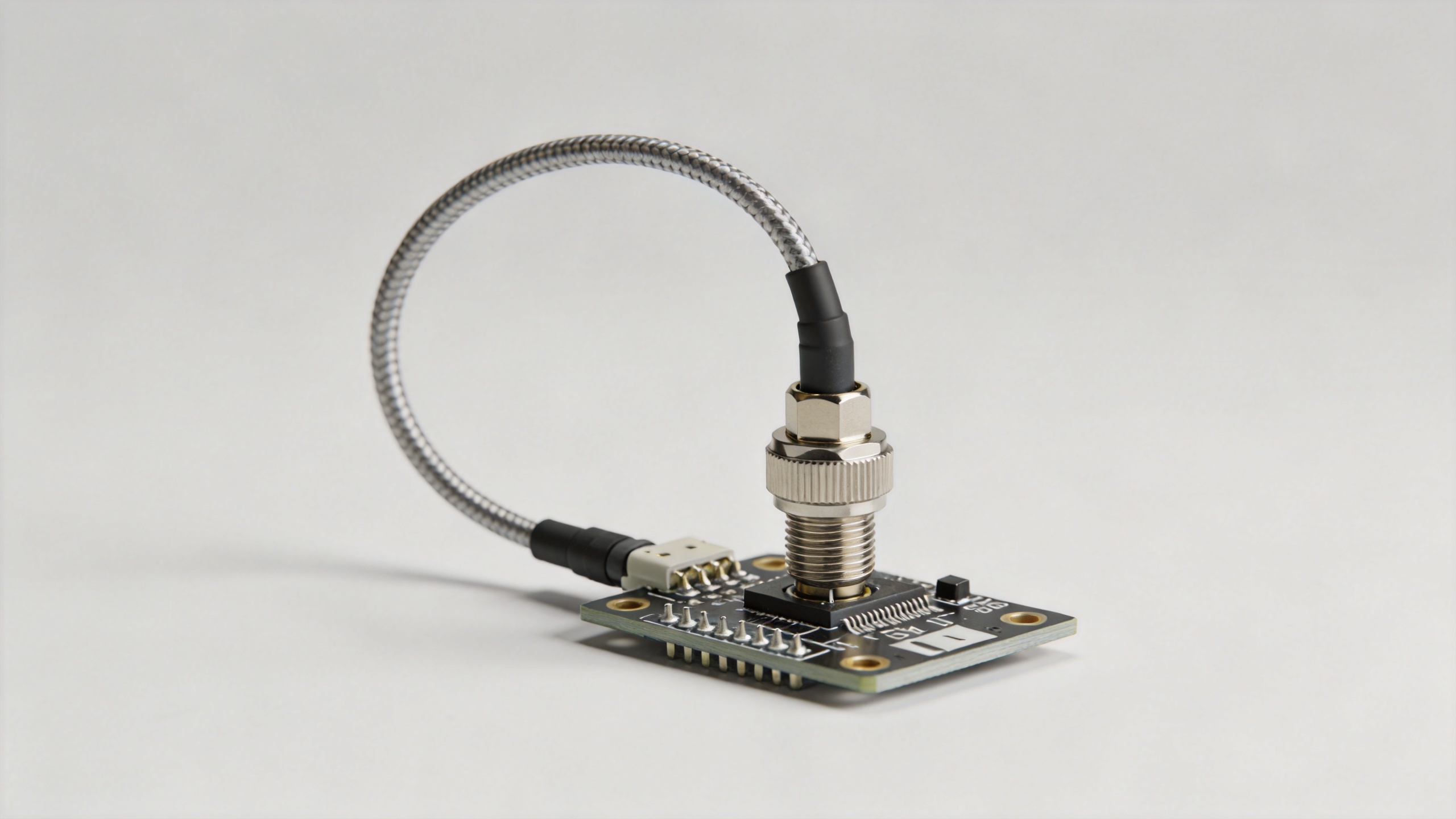
U.FL is designed for compact board-level use, so vertical clearance matters. Supplier documentation for the U.FL series shows low mated profiles, but exact height varies by version. Confirm that the enclosure lid, battery, shield can, heat sink, and neighboring components do not interfere with the mated plug or cable exit.
Also define the assembly procedure. Align the U.FL plug vertically, press it into place with an appropriate tool or controlled technique, and avoid levering the cable sideways. Limit unnecessary mate/unmate cycles during prototype work and service. Before a production run, let the team inspect a real assembly in the final enclosure rather than relying solely on a CAD view.
Use an integration checklist before approving the BOM
| Check | What to confirm | Why it matters |
|---|---|---|
| Board interface | Exact U.FL-family receptacle and compatible plug | Prevents mechanical mismatch and board damage |
| SMA end | Standard or RP-SMA, gender, bulkhead geometry | Prevents an antenna-side connection error |
| Electrical path | 50-ohm system, assembly frequency range, test data | Protects return loss and link-budget assumptions |
| Cable route | Length, bend radius, strain relief, shielding | Controls loss and long-term mechanical reliability |
| Acceptance test | Visual inspection plus the RF check required by the application | Finds integration errors before deployment |
Turn the checklist into a supplier RFQ
A useful RFQ for a ufl to sma connector assembly states the board-side interface, SMA configuration, cable type, finished length, operating band, environment, routing constraint, and required test evidence. For related coax termination requirements, review this RF N female connector for RG58, 3D-FB, LMR195 and LMR200 cable as part of a broader RF interconnect sourcing discussion; its product page should not be treated as a substitute for a U.FL-to-SMA assembly specification.
The right ufl to sma connector is the one that fits the exact board interface, preserves the intended RF path, survives the installed cable route, and can be verified with your real enclosure and test plan. That approach is slower than ordering by connector name alone, but it is far less expensive than correcting an avoidable integration issue after the design is frozen.