EN
EN

RF Connector Types Explained: SMA, N, BNC and MMCX
Choosing among RF connector types is not simply a matter of finding two parts that screw or snap together. The connector sits at the transition between a cable, an antenna, a radio, a test instrument, or a PCB. A mismatch in interface, impedance, cable termination, or environmental protection can create an unreliable assembly even when every individual part looks correct. For telecom equipment teams, lab buyers, and OEM engineers, a sound comparison starts with the mechanical coupling method and ends with the complete RF path.
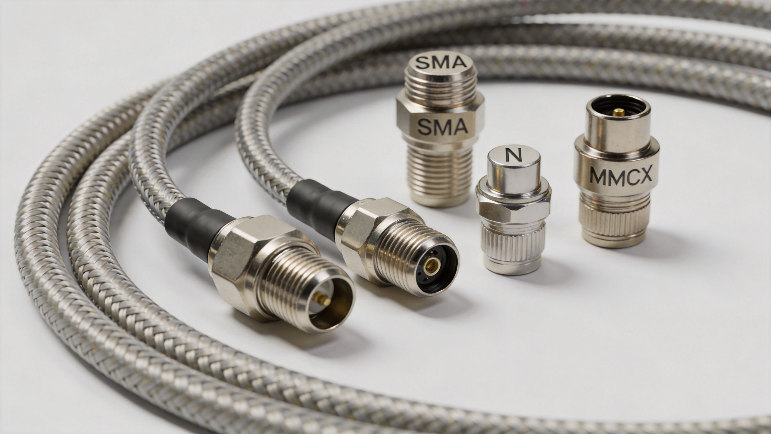
This guide explains four widely encountered RF connector types: SMA, N, BNC, and MMCX. It focuses on what each family is built to do, where it fits, and which checks should happen before a purchase order or cable-assembly drawing is released.
Start with the job, not the connector name
Most RF coaxial connectors fall into a few practical coupling styles. Threaded interfaces resist loosening and are often chosen for vibration or outdoor exposure. Bayonet interfaces connect quickly, which is useful on benches and service equipment. Snap-on interfaces minimize space and handling time in compact products. These differences matter because a connector’s usable frequency is only one part of its suitability.
When comparing RF connector types, define the application first: the frequency band, 50-ohm or 75-ohm system impedance, required mating cycles, cable type, pull and bend constraints, enclosure space, and whether the assembly will see moisture, vibration, or repeated field service. Then verify the exact manufacturer datasheet for the selected series. Frequency ratings can vary by connector configuration and the cable assembly behind it.
SMA: compact threaded performance for higher-frequency work
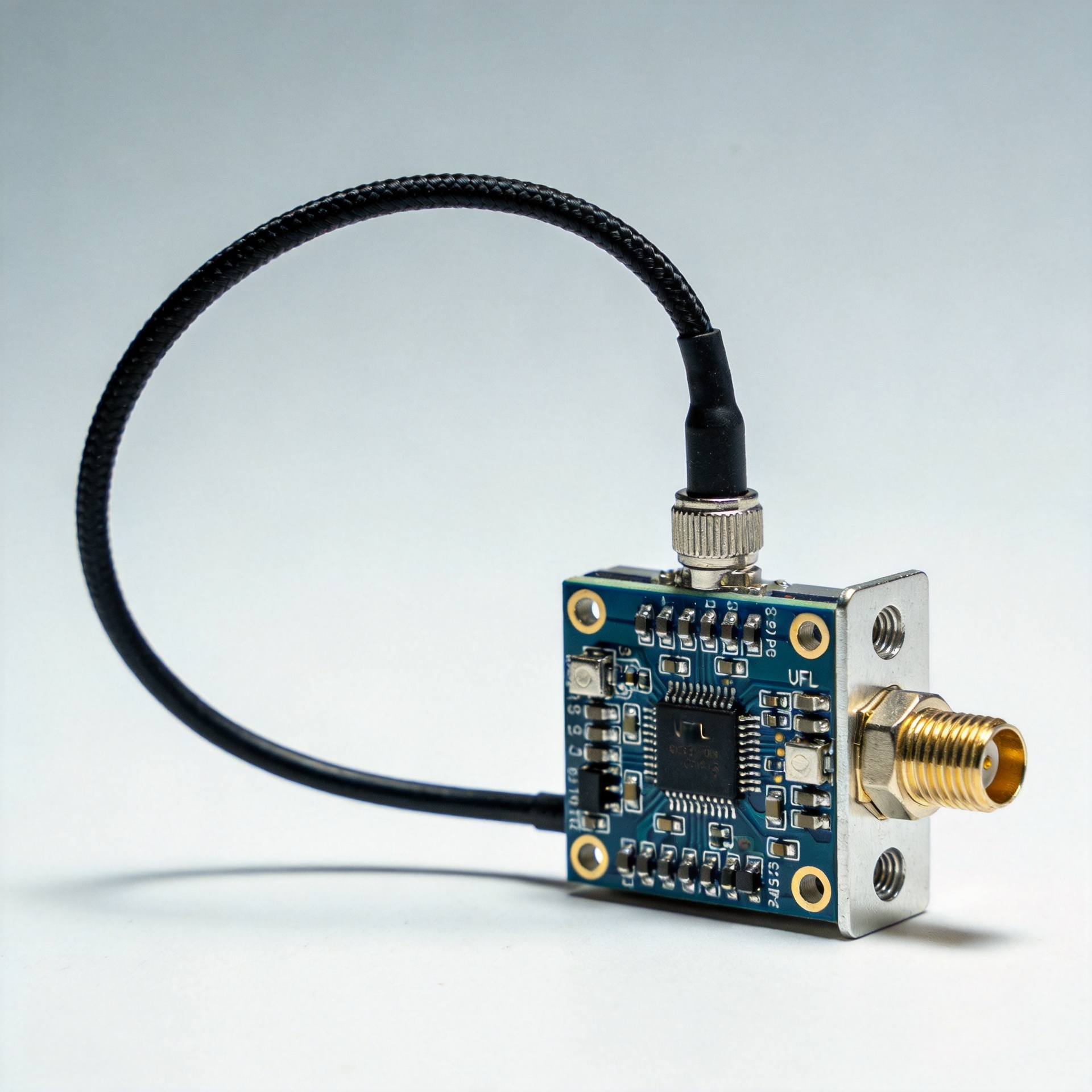
SMA is a widely used RF connector type for antennas, RF modules, lab fixtures, and compact cable assemblies. Its small threaded coupling provides a positive mechanical connection, which helps where vibration or repeated handling would make a loose push-on interface undesirable. SMA is commonly associated with higher-frequency RF work; the actual upper frequency limit depends on the connector series, cable, and assembly quality.
The key selection benefit is its combination of small size and threaded retention. The key risk is assuming every visually similar SMA-family interface mates correctly. Standard SMA and reverse-polarity SMA are different interface arrangements. Confirm the gender convention and the center-contact configuration from the drawing rather than ordering from a product photo or a shorthand description.
Use SMA when space is constrained but a threaded connection is preferred. It is a common fit for radio modules, antenna leads, test leads, and embedded equipment. Specify the cable and termination style alongside the connector: a connector choice without the correct cable diameter and construction is not a complete solution.
N connector: robust threaded choice for larger cables and exposed installations
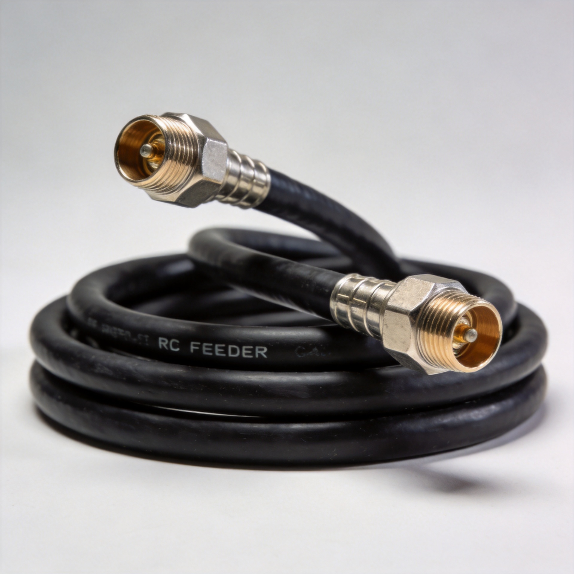
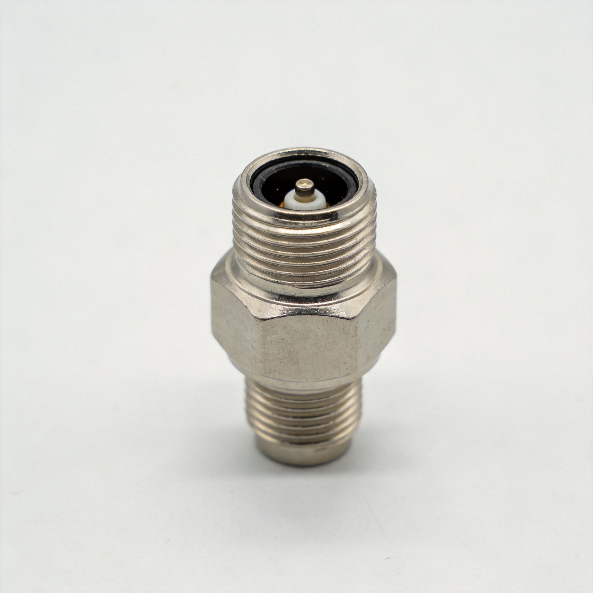
The n connector is a medium-size threaded interface valued for mechanical robustness and outdoor-oriented RF installations. Compared with compact interfaces, it gives designers more physical scale for larger coaxial cables and a connection that can be tightened deliberately during installation. This makes it familiar in base-station, antenna-feed, broadcast, field measurement, and infrastructure work.
Standard N-Type designs are commonly specified through 11 GHz, while extended-range designs can reach higher frequencies; use the exact supplier specification for the selected part. A threaded body alone does not make an assembly weatherproof. For an outdoor n connector installation, review the cable-entry seal, boot or weatherproofing method, torque guidance, corrosion exposure, and the mating connector’s condition.
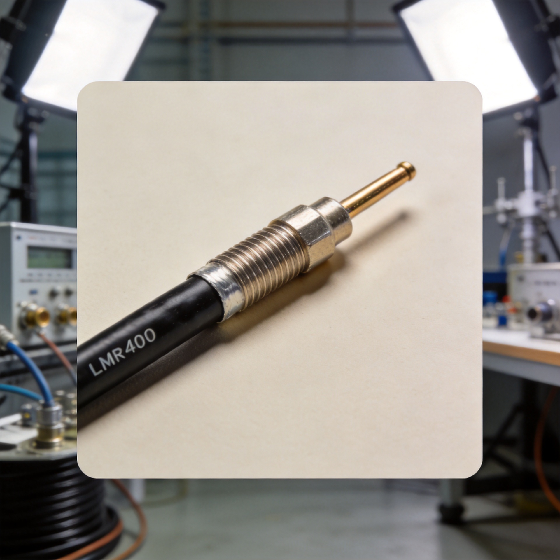
For cable assemblies using RG58, 3D-FB, LMR195, or LMR200-style cables, the cable-specific connector design is essential. For example, teams sourcing an N-female cable-end solution can review the available RF N Female Connector for RG58, 3D-FB, LMR195 and LMR200 Cable as a starting point, then confirm dimensions and assembly requirements against the final cable specification.
BNC: fast bayonet mating for test, video, and service work
BNC is among the most recognizable RF connector types because its bayonet coupling locks with a short twist. That speed is valuable on test benches, laboratory instruments, legacy video systems, monitoring equipment, and service connections where technicians may connect and disconnect frequently. The bayonet mechanism also makes visual confirmation of a connected interface straightforward.
BNC should be selected with more care than its familiar appearance suggests. Both 50-ohm and 75-ohm BNC variants exist, and their intended applications differ. A team should not treat impedance as a cosmetic option: use the impedance required by the system and verify the plug, jack, cable, and instrument interface together. BNC is often practical for moderate-frequency work, but the final performance limit remains dependent on the series and assembly.
MMCX: a miniature snap-on interface for space-limited electronics
MMCX addresses a different design problem: making an RF connection where board area, enclosure volume, and cable routing are tightly constrained. Its miniature snap-on format is common in compact wireless devices, internal antennas, GPS equipment, and small modules. Product families are commonly specified from DC to 6 GHz, but the datasheet for the exact mating pair should govern the design.
The trade-off is clear. MMCX can reduce package size and simplify assembly, but its small geometry demands thoughtful cable strain relief and careful handling. Avoid routing a heavy or frequently flexed cable so that it loads the connector directly. If field technicians must repeatedly mate the cable, consider whether a larger interface with better handling clearance will lower service risk.
A practical comparison of these RF connector types
| Type | Coupling | Typical selection strength | Common caution |
|---|---|---|---|
| SMA | Threaded | Compact, secure connection for RF modules and higher-frequency work | Verify standard SMA versus RP-SMA and the exact series rating |
| N | Threaded | Robust cable and outdoor/infrastructure applications | Confirm cable fit, sealing method, and specified frequency range |
| BNC | Bayonet | Fast mating for test, service, and video-related equipment | Do not mix 50-ohm and 75-ohm requirements casually |
| MMCX | Snap-on | Miniature internal connections in compact equipment | Plan strain relief and mating access carefully |
Five checks before specifying a connector or cable assembly
- Confirm the mating interface. Check interface family, gender, center contact, and any reverse-polarity convention.
- Match impedance end to end. Review the radio, cable, connector, adapter, and antenna as one path.
- Validate the cable termination. Cable OD, dielectric construction, braid, and stripping dimensions affect whether a connector is compatible.
- Use the published performance data. Verify frequency range, VSWR or return-loss requirements, power conditions, and environmental limits for the selected series.
- Design for installation. Consider torque access, bend radius, weather sealing, vibration, mating cycles, and future serviceability.
RF connector types selection checklist: compare RF connector types by interface family; compare RF connector types by impedance; compare RF connector types by cable diameter; compare RF connector types by coupling style; compare RF connector types by frequency specification; compare RF connector types by enclosure space; compare RF connector types by installation access; compare RF connector types by environmental sealing; compare RF connector types by service cycles; compare RF connector types by approved drawings. For an n connector assembly, verify the n connector cable fit, the n connector mating interface, and the n connector sealing arrangement. This RF connector types checklist is intended to prompt a drawing and datasheet review before release, not to replace the product-specific specification.
Choose the interface that makes the whole RF path easier to control
The most useful way to compare RF connector types is to choose the interface that supports the full mechanical and electrical context. SMA is a strong compact threaded option; the n connector favors robust cable and exposed infrastructure work; BNC supports fast, familiar service connections; and MMCX helps engineers protect valuable board space. Once the application is defined, validate the exact connector series and cable combination with the manufacturer’s drawing and datasheet before production.