EN
EN

Understanding Coaxial Cable Loss in RF Feeder Design
In an RF feeder, cable loss is not a minor line item. It is the portion of transmitted signal power that does not reach the antenna, receiver, or test port because the coaxial line dissipates energy along the route. When a link budget is tight, an apparently small attenuation value can reduce margin, change coverage expectations, or mask the performance of otherwise well-matched equipment. The practical question is therefore not whether a feeder has loss—all real coax does—but whether the expected loss is understood, budgeted, and controlled before installation.
This article explains the mechanisms behind coax cable loss, why frequency and length matter so much, and how RF engineers can evaluate a feeder path without confusing normal attenuation with avoidable installation problems.
What Cable Loss Means in an RF Feeder
Cable loss, also called attenuation or insertion loss, is normally expressed in decibels (dB). A 0 dB line would deliver all input power to its far end; every positive dB value represents a reduction. For power measurements, the relationship is expressed as loss (dB) = 10 × log10(Pin/Pout). This logarithmic form is useful because individual feeder sections, connectors, jumpers, and protective devices can be added as dB values in a link budget.
For feeder design, keep two ideas separate. First, published cable loss is the distributed attenuation of a specific cable at a stated frequency and reference length. Second, a poor termination, damaged connector, sharp bend, or moisture path may introduce mismatch or intermittent behavior that is not captured by the clean datasheet attenuation figure. A good design reviews both.
Where Coax Cable Loss Comes From
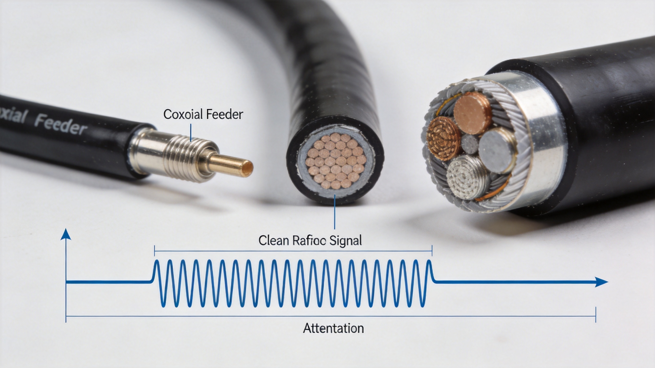
Coaxial attenuation is usually the combined result of conductor loss and dielectric loss. RF current tends to concentrate near conductor surfaces as frequency rises, increasing effective resistance through skin effect. At the same time, the insulating material between the center conductor and shield absorbs a small part of the RF energy. In practical loss models, conductor loss rises approximately with the square root of frequency, while dielectric loss rises approximately in proportion to frequency.
- Conductor loss: affected by conductor material, surface quality, conductor dimensions, and the RF current distribution on the center conductor and shield.
- Dielectric loss: affected by dielectric material and construction. Its influence becomes increasingly important as operating frequency increases.
- Shield and construction effects: braid coverage, corrugation, foam geometry, and manufacturing consistency influence real-world attenuation and stability.
- Interface effects: connector quality, torque, cleanliness, weather sealing, and bend radius can add loss or reflection beyond the nominal cable value.
These mechanisms explain why “same impedance” does not mean “same coax cable loss.” Two 50-ohm cables can be electrically compatible yet show very different attenuation per meter at the same frequency.
Why Frequency and Length Drive the Result
Datasheets usually state attenuation as dB per 100 m, 100 ft, or another fixed length at selected frequencies. That presentation matters: a value is meaningful only with its frequency, temperature, and length basis. If a cable is listed at 3 dB per 100 m at the intended band, a 200 m run begins with about 6 dB of line attenuation before connector and jumper allowances. The same physical run will generally have greater cable loss at a higher frequency.
Length is normally the easiest contributor to estimate because distributed attenuation scales approximately with installed length. Frequency requires more care. Do not extrapolate a low-band figure linearly into a microwave band unless the manufacturer provides a curve or table. The combined conductor and dielectric mechanisms do not follow one simple straight-line rule over every cable design and frequency range.
| Design input | Why it matters | Practical check |
|---|---|---|
| Operating frequency range | Attenuation rises as frequency rises. | Use the value at the highest relevant operating frequency, not only at the nominal center frequency. |
| Installed route length | Distributed loss accumulates along the feeder. | Measure the actual routing path and include service loops and vertical runs. |
| Cable construction | Conductor and dielectric choices influence attenuation. | Compare manufacturer data on an equal length and frequency basis. |
| Interfaces and environment | Connectors and exposure can create additional loss or mismatch. | Specify compatible interfaces, torque practice, bend radius, and sealing where needed. |
A Simple Cable Loss Evaluation Workflow
Start with the system requirement rather than a cable family name. Define transmit power or receiver sensitivity, operating band, allowable feeder budget, expected route length, connector count, and environmental conditions. Then evaluate the proposed coax against the highest-frequency requirement and the longest installed path that the layout permits.
- Read attenuation in the correct units. Convert the datasheet value to the actual installed length. Keep units consistent before adding values.
- Add planned discrete losses. Include only verified allowances for connectors, adapters, arrestors, splitters, or jumpers. Avoid inventing a “typical” number when component data is available.
- Check the link margin. Compare total estimated cable loss with the remaining transmit or receive budget.
- Validate the installation. Measure insertion loss or use suitable RF test methods after assembly, especially on long, high-frequency, or mission-critical feeder routes.
- Document the assumptions. Record frequency, length, cable part number, interfaces, and reference conditions so later service teams can diagnose deviations.
For a low-loss flexible feeder option, the verified product record for HCAAY(Z)-50-12 1/2-inch low-loss flexible cable can be evaluated with this same workflow. Its actual attenuation, power, and installation suitability should be confirmed from the applicable product documentation for the operating band and route conditions.
How to Avoid Underestimating Coax Cable Loss
Several shortcuts create avoidable errors. One is comparing cable attenuation at different frequencies and declaring one option lower loss without normalizing the conditions. Another is using the straight-line building distance instead of the installed route length. A third is assuming that a feeder’s datasheet value includes every field connector, adapter, and environmental effect.
For awareness-stage planning, the most useful habit is to build a small cable loss worksheet early. List the route segments, cable types, lengths, specified attenuation values, and known interfaces. This makes tradeoffs visible: a larger or lower-loss feeder may reduce link loss, while route constraints, flexibility, termination options, and installation practices may influence the final choice.
Measurement Confirms the Design Assumption
Calculation is necessary, but it is not the final proof. A measured result that differs materially from the estimate can indicate an incorrect length assumption, an unsuitable frequency reference, unexpected connector loss, water ingress, a damaged cable, or a mismatch elsewhere in the path. Use measurement methods appropriate to the system and test equipment, and compare against the documented design assumptions rather than against a generic expectation.
It is also useful to separate attenuation measurements from return-loss or VSWR checks. A feeder may show acceptable distributed coax cable loss yet still have a poor interface that reflects energy. Reviewing both helps engineers avoid treating every RF performance issue as a simple cable-length problem.
Key Takeaway for RF Feeder Design
Effective feeder design treats cable loss as a predictable engineering input. Select the cable using attenuation at the operating frequency, multiply it by the actual installed length, include verified interface allowances, and reserve margin for the system objective. Then validate the assembled route. This approach turns coax cable loss from an after-installation surprise into a controlled part of RF link performance. For related RF interconnect resources, visit Zhenjiang Jiewei Electronic Technology Co.,Ltd.