EN
EN

How to Select RF Cable Connector Types for Coaxial Assemblies
Choosing rf cable connector types is not a catalog exercise. For a coaxial assembly, the connector has to preserve the electrical behavior of the cable while also fitting the equipment port, the installation method, and the operating environment. A connector that looks right on a parts list can still be the wrong choice when its termination is incompatible with the cable construction or its coupling style is impractical at the installation site.
For telecom, antenna, test, and OEM buyers, the most useful way to compare rf cable connector types is to move from system requirements to the finished assembly. Start with impedance and frequency, then verify cable geometry, mating interface, termination process, and environmental exposure. That order prevents a familiar connector family from becoming the default before it has earned its place in the design.
Begin with the RF system, not the connector name
The first filter for rf cable connector types is the system impedance. RF coaxial systems commonly use 50 Ω or 75 Ω architectures, and the cable, connector, and mating port should be specified for the same nominal impedance. Mixing interfaces without a deliberate transition design can introduce mismatch and reflections, which may show up as poorer return loss or a higher VSWR.
Frequency is the next gate. A connector series may be physically compatible with a cable but unsuitable for the operating band or the performance margin required by the assembly. Do not interpret a higher frequency rating as automatically better. If the application runs well below that rating, extra margin may add cost or mechanical constraints without solving the actual limitation. Instead, compare the specific connector and assembly data for the planned band, including insertion loss and return-loss behavior where available.
At this stage, put rf cable connector types into three practical groups: rugged threaded interfaces for outdoor or higher-retention installations; compact threaded or snap-on interfaces for equipment and instrument connections; and precision or blind-mate interfaces for high-frequency, dense, or repeatable system interconnects. The right group depends on the RF path, not on which name appears most often in a previous bill of materials.
Match the connector to the actual coaxial cable
Cable compatibility is where many selection lists become too broad. When reviewing rf cable connector types, confirm the cable outer diameter, dielectric construction, center conductor diameter and material, braid or foil arrangement, and jacket thickness. A connector sold for a cable family may still have a different ferrule, pin, clamp, or stripping dimension for a closely related cable variant.
Ask a simple question before issuing an RFQ: can the selected termination method repeatably fit this exact cable construction? Crimp, clamp, solder, and captive-contact designs each impose different process controls. A small cable for an internal instrument harness may favor a compact crimp solution, while a larger feeder assembly may need a connector whose strain relief and coupling hardware suit the cable weight and bend radius.
That is also why rf cable connector types should be reviewed together with the assembly drawing. The connector body may clear the port, but a straight exit may not clear the enclosure or cable tray. When routing is tight, a right-angle version can be the better system choice even if a straight connector is easier to source. Mechanical fit is not separate from RF performance when poor routing creates stress at the termination.
Compare common connector families by use case
| Connector family | Typical decision context | What to verify on the assembly |
|---|---|---|
| N-type | Rugged 50 Ω antenna, telecom, outdoor, and general-purpose RF paths | Specific frequency range, cable-specific termination, sealing approach, coupling access |
| SMA / RP-SMA | Compact equipment, test, wireless modules, and higher-frequency cable runs | Polarity and mating interface, torque practice, cable size, frequency limit |
| BNC | Quick-connect test, video, and lower-frequency instrument contexts | Impedance version, bayonet retention, mating-cycle needs, cable fit |
| TNC / RP-TNC | Threaded compact RF connections where vibration resistance is relevant | Thread type, polarity, installation clearance, cable-specific tooling |
| Precision or blind-mate interfaces | Dense, high-frequency, board-level, or repeatable module connections | Alignment tolerance, mating-cycle rating, frequency performance, manufacturer-specific interface rules |
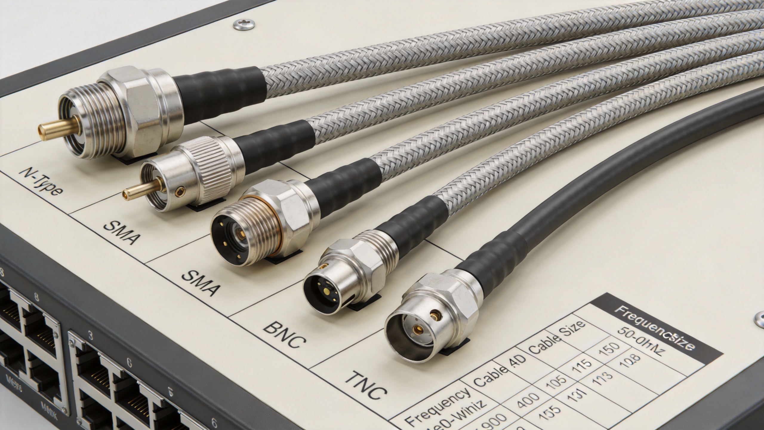
This table is a starting point, not a substitute for the part-level datasheet. For example, N-type is often considered for robust 50 Ω RF installations, but the usable frequency range, sealing level, and cable compatibility vary by series. The same rule applies across all rf cable connector types: select the family by scenario, then validate the exact part and cable combination.
Choose a termination and mounting style that the site can support
Termination is a production and field-service decision as much as an electrical one. For rf cable connector types, determine whether the assembly will be factory-built, field-terminated, or repaired in service. A field-installable design can reduce downtime, but only if the crew has the specified tools, stripping dimensions, torque procedure, and inspection method. A factory-terminated cable assembly may be preferable when repeatability and incoming inspection are more important than on-site flexibility.
Mounting style also matters. Cable-mount, bulkhead, panel-mount, PCB-mount, and adapter configurations solve different interface problems. Before approving rf cable connector types, check the mating gender, polarity convention, panel thickness, wrench clearance, and whether the connector will be repeatedly mated during maintenance. These details are often the reason an electrically acceptable choice becomes difficult to install.
Treat environment and reliability as selection gates
For indoor laboratory assemblies, electrical specifications may dominate the decision. For rooftop, transportation, industrial, or outdoor radio installations, rf cable connector types must also be screened for moisture exposure, UV, temperature cycling, vibration, corrosion risk, and access for weatherproofing. An ingress rating alone does not describe every outdoor stressor; verify the specified conditions and the installation method needed to preserve protection after mating.
Here is a question worth asking before final release: how many times will this connection be mated, inspected, or serviced during its intended life? A high-performance interface with limited practical access can be less useful than a well-matched standard interface that technicians can install and replace correctly. For a multi-site deployment, standardization may simplify spares and training, but only after the standardized choice passes every site’s frequency, cable, and environment requirements.
Use a five-step selection checklist
- Define system impedance, operating frequency, performance budget, and mating port.
- Document the exact coaxial cable construction, outer diameter, center conductor, and routing constraints.
- Shortlist rf cable connector types that match both the electrical interface and the cable-specific termination.
- Compare termination method, mounting style, sealing, vibration exposure, service access, and tooling requirements.
- Qualify the completed assembly with the checks appropriate to the application, then control the approved cable/connector combination in purchasing and production.
When an application calls for an N-family cable interface, a cable-specific option such as RF N Female Connector for RG58, 3D-FB, LMR195 and LMR200 Cable can be evaluated against the actual cable and environmental requirements. For pre-terminated interconnect needs, an N Male to N Male Cable Assembly for RG405, RG402 and RG401 provides a useful reference point for discussing connector and cable combinations.
Final decision: specify the assembly, not just the interface
A reliable way to select rf cable connector types is to specify the complete coaxial assembly: frequency and impedance, exact cable, connector part family, termination method, mating interface, routing, environment, and verification plan. Both a compact connector and a rugged threaded connector can be valid choices. The correct answer depends on the system requirements and the conditions in which the finished assembly must perform.