EN

LMR-400 vs LMR-600 Coaxial Cable: How to Choose
Choosing an LMR-400 coaxial cable is rarely about asking whether it is a good cable in isolation. The real question is whether its attenuation, diameter, flexibility, connector options, and installation path match the RF link you are building. LMR-600 can reduce loss on a long run, but it brings a larger physical footprint. For many telecom, DAS, antenna, and test-system projects, the better choice comes from comparing the complete signal path rather than selecting the largest cable by default.
As an RF systems engineer would approach the decision, start with the link budget at the operating frequency, then check the routing path, terminations, and environmental exposure. Both cable families are commonly used as 50-ohm low-loss RF coax in applications that may extend through the GHz range, but the exact construction and ratings should be confirmed against the datasheet for the cable variant and assembly you intend to buy.
Start with the electrical decision: loss budget and run length
An LMR-400 coaxial cable is often the practical middle ground when a project needs lower loss than general-purpose coax without making installation unnecessarily difficult. LMR-600 is physically larger and is normally considered when the run is long enough, or the operating frequency high enough, that lower attenuation materially improves the received or transmitted signal margin.
Do not compare attenuation only at one frequency. Ask the supplier to provide attenuation per unit length at your actual operating band, then multiply it by the proposed route length and include connector, lightning-protection, splitter, and jumper losses. A representative LMR-400 listing reports 3.9 dB per 100 ft at 900 MHz, but that is an illustrative, construction-specific figure—not a value to copy into every design. The same discipline applies to LMR-600: verify its exact loss curve, not just the family name.
Here is the useful rule: if the calculated margin is already comfortable with LMR-400, moving to LMR-600 may add cost and routing complexity without delivering a meaningful system benefit. If the margin is tight, a long feeder run is unavoidable, or the system operates at a higher band where loss rises, LMR-600 deserves more weight.
LMR-400 vs LMR-600: compare the installation trade-offs
| Selection factor | LMR-400 focus | LMR-600 focus |
|---|---|---|
| Electrical loss | Suitable for many moderate-length low-loss RF runs | Typically selected when a lower-loss long-run solution is needed |
| Physical size | A common reference diameter is about 0.405 in; easier to route in constrained paths | A common reference diameter is about 0.59 in; requires more routing space |
| Termination planning | More manageable where connector access and cable handling are limited | Needs connector and strain-relief choices sized for the larger cable |
| Project fit | Balanced choice for many equipment, antenna, and indoor/outdoor feeder routes | Best evaluated for long feeders, higher-frequency loss budgets, and fixed routes |
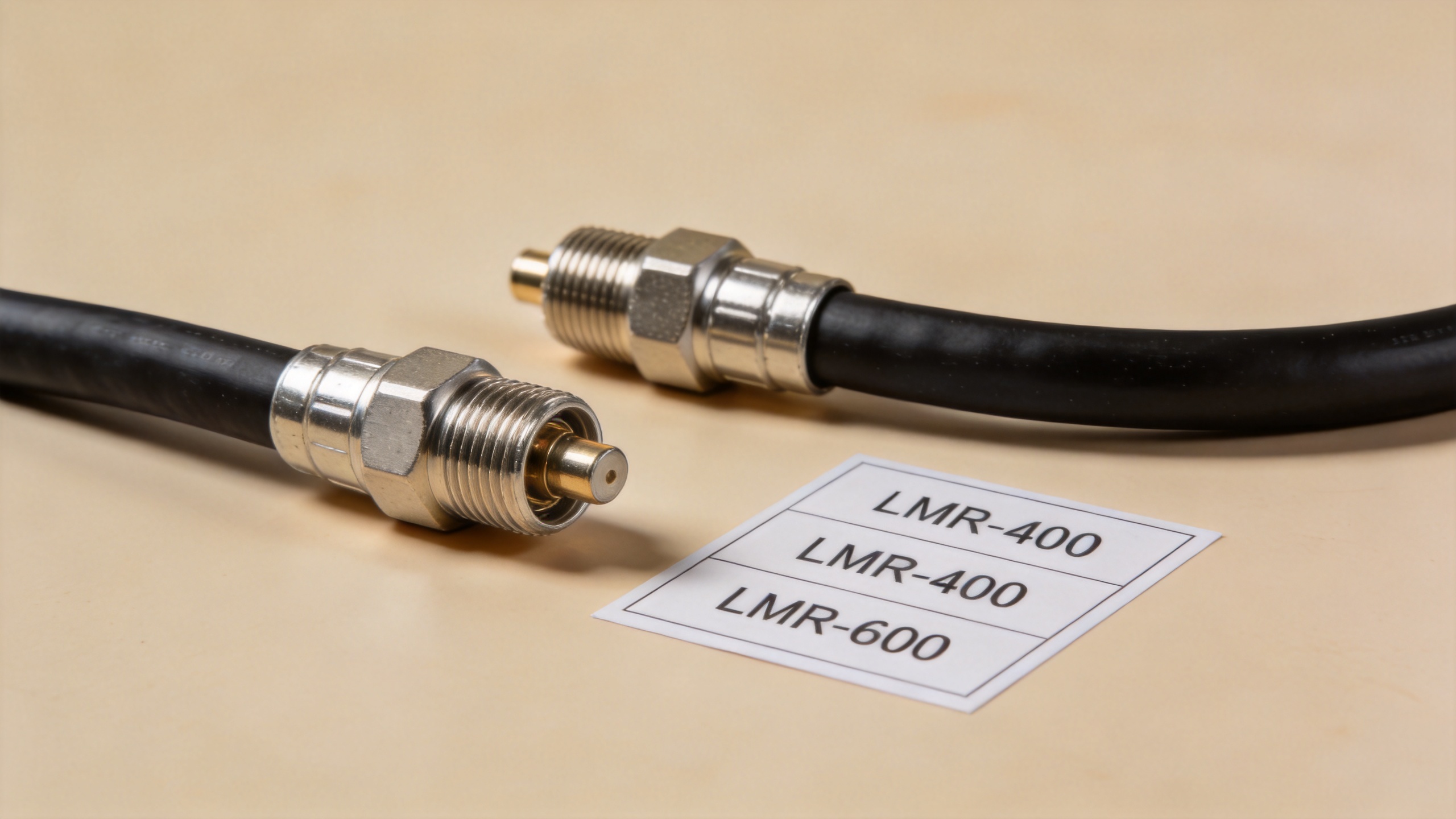
The mechanical side matters as much as the attenuation number. A larger feeder can be the correct electrical answer but the wrong installation answer if a tray is crowded, the bend path is tight, or the connector must be serviced in a small enclosure. In that situation, an LMR-400 coaxial cable with a verified loss budget can be the more reliable project choice.
One question worth asking before finalizing the RFQ is: where will the cable actually turn, terminate, and be maintained? Cable diameter affects bend planning, pulling effort, connector selection, and strain relief. Those details can determine whether the theoretical low-loss advantage survives installation.
Check more than attenuation before you release an RFQ
For either cable size, a clear specification package prevents the familiar problem of receiving an assembly that looks right but does not match the intended interface. Include these points:
- Impedance and frequency: specify the required 50-ohm system impedance and the operating band, then request the applicable data for the exact cable construction.
- Length and loss limit: define finished assembly length and the maximum acceptable attenuation at the frequencies that matter.
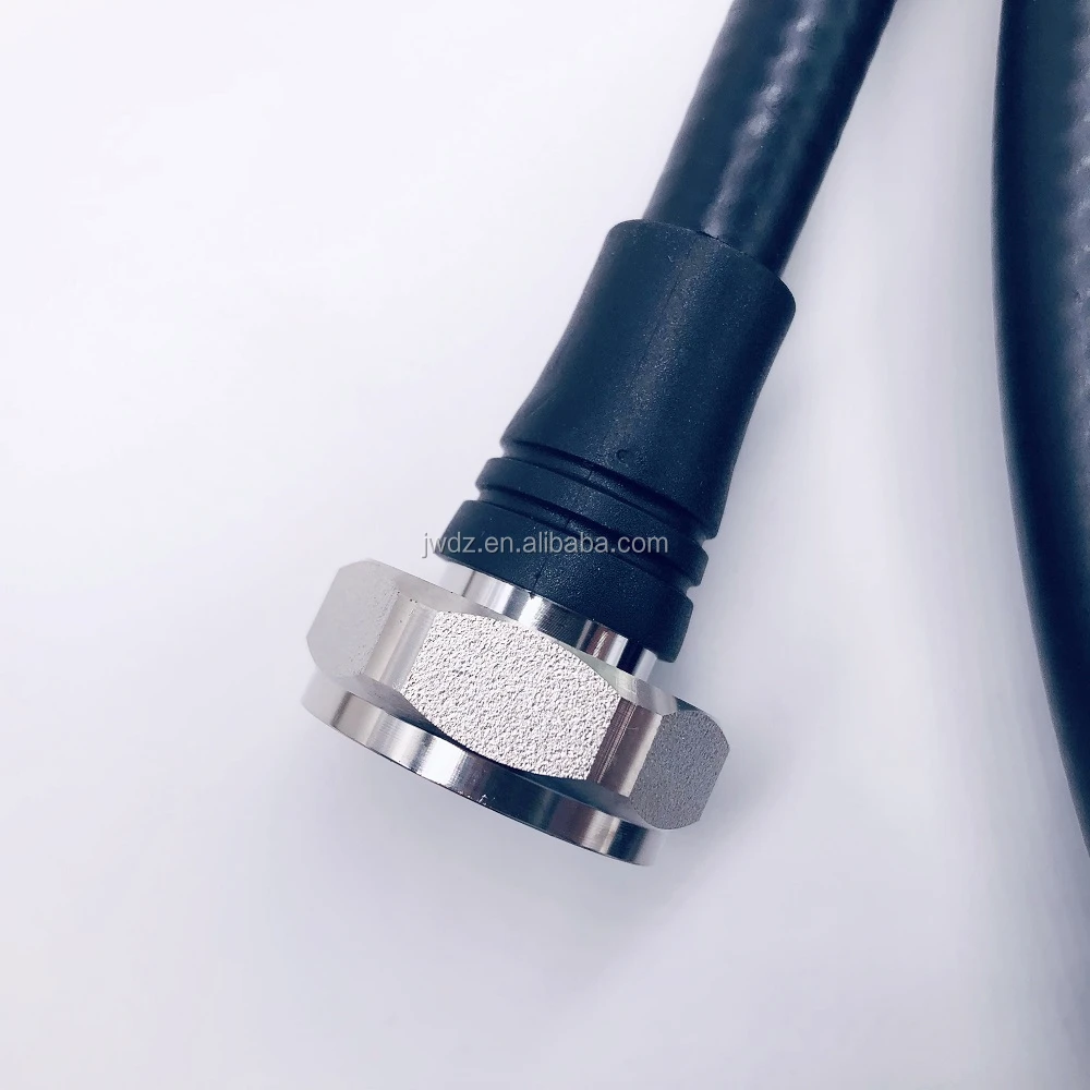
- Connector interfaces: identify connector series, gender, orientation, and mating-side requirements. The connector must be compatible with the cable size as well as the equipment port.
- Routing and bend path: confirm the planned installation can respect the supplier’s minimum bend-radius guidance, especially near antenna bases and cabinets.
- Environment: state whether the route faces UV, moisture, vibration, temperature cycling, or outdoor exposure. A jacket description alone is not a complete environmental qualification.
- Verification: ask what inspection or test data can be supplied for the completed assembly, such as continuity, VSWR, or insertion-loss checks when appropriate.
It is tempting to say the cable loss figure is the whole story. It is not, quite. At short lengths, connector quality, seating, and impedance continuity can be as influential as the difference between two cable sizes. At long lengths, the cable attenuation may become the dominant design variable. The decision changes with the route.
When LMR-400 is usually the better fit
Choose an LMR-400 coaxial cable when you need a low-loss 50-ohm feeder that can still be routed through typical equipment rooms, antenna supports, cabinets, or indoor/outdoor pathways. It is a strong candidate where cable management, installation access, and replacement practicality matter alongside RF performance.
It also makes sense when the system has a reasonable link margin and the route is not long enough to justify the added diameter of LMR-600. This is not a compromise based on price alone; it is an engineering decision based on the total installed system. For multi-site deployments, LMR-400 may also simplify spare planning and installer familiarity, provided the same loss and environmental requirements are met at every site.
When LMR-600 is worth the added size
Move toward LMR-600 when the feeder is long, the operating frequency pushes attenuation upward, or the design needs every practical fraction of RF margin. Its larger form factor is easier to justify on a fixed, accessible route than in a crowded enclosure or a sharply constrained cable path.
LMR-600 can also be a sensible option when an upgrade later would require expensive re-cabling. Still, higher capacity is not automatically better. If the actual system operates well within the LMR-400 loss budget, over-specifying the feeder may consume budget and installation space that would be better used for robust connectors, weatherproofing, or testing.
Specify the cable assembly, not just the cable family
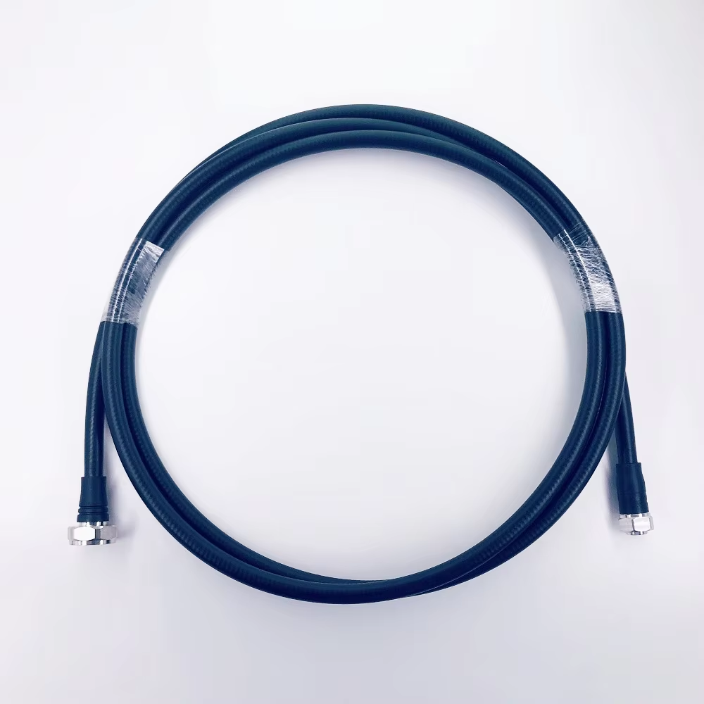
The final procurement item is often a terminated assembly rather than bulk cable. That is why the connector combination, finished length, and inspection expectation should appear in the same RFQ as the cable family. Where a low-loss LMR-600 jumper is needed, review the available LMR600 coaxial cable assembly with 4.3/10 male to N male connectors as a reference for matching the assembly interface to the installation—not as a substitute for confirming your own frequency, length, and connector requirements.
Make the selection with a short decision checklist
- Calculate the end-to-end loss budget at the real operating frequencies.
- Compare the required route length with the loss difference between the exact LMR-400 and LMR-600 variants.
- Validate tray space, bend path, access, and connector clearance before choosing the larger cable.
- Specify connectors, jacket needs, and test expectations together with the cable.
- Request the supplier datasheet and assembly verification data before approving production.
LMR 400 coaxial cable FAQ
Is an lmr 400 coaxial cable suitable for outdoor RF routes?
An lmr 400 coaxial cable can suit an outdoor route when the exact jacket, connector sealing method, and environmental ratings meet the project specification. Confirm the supplier documentation for the selected lmr 400 coaxial cable assembly rather than assuming every construction has the same outdoor rating.
Does an lmr 400 coaxial cable cost less to install than LMR-600 in every project?
Not automatically, but an lmr 400 coaxial cable may reduce routing difficulty where cable trays, bends, and connector access are constrained. Compare total installation labor, support hardware, and the loss budget before selecting an lmr 400 coaxial cable or a larger feeder.
What should be tested on an lmr 400 coaxial cable assembly?
For an lmr 400 coaxial cable assembly, the appropriate acceptance checks depend on the application, but can include continuity, connector interface verification, and RF checks such as VSWR or insertion loss where required. Put those requirements in the RFQ for the exact lmr 400 coaxial cable length and connector pair.
In summary, an lmr 400 coaxial cable is often the balanced choice for low-loss RF routes that still need manageable installation. LMR-600 is the stronger candidate when the loss budget clearly benefits from a larger feeder and the route can accommodate it. Both can be valid options; the right answer is the one that satisfies your electrical margin and your real installation conditions at the same time.