EN

MCX Connector Basics for Compact RF Applications
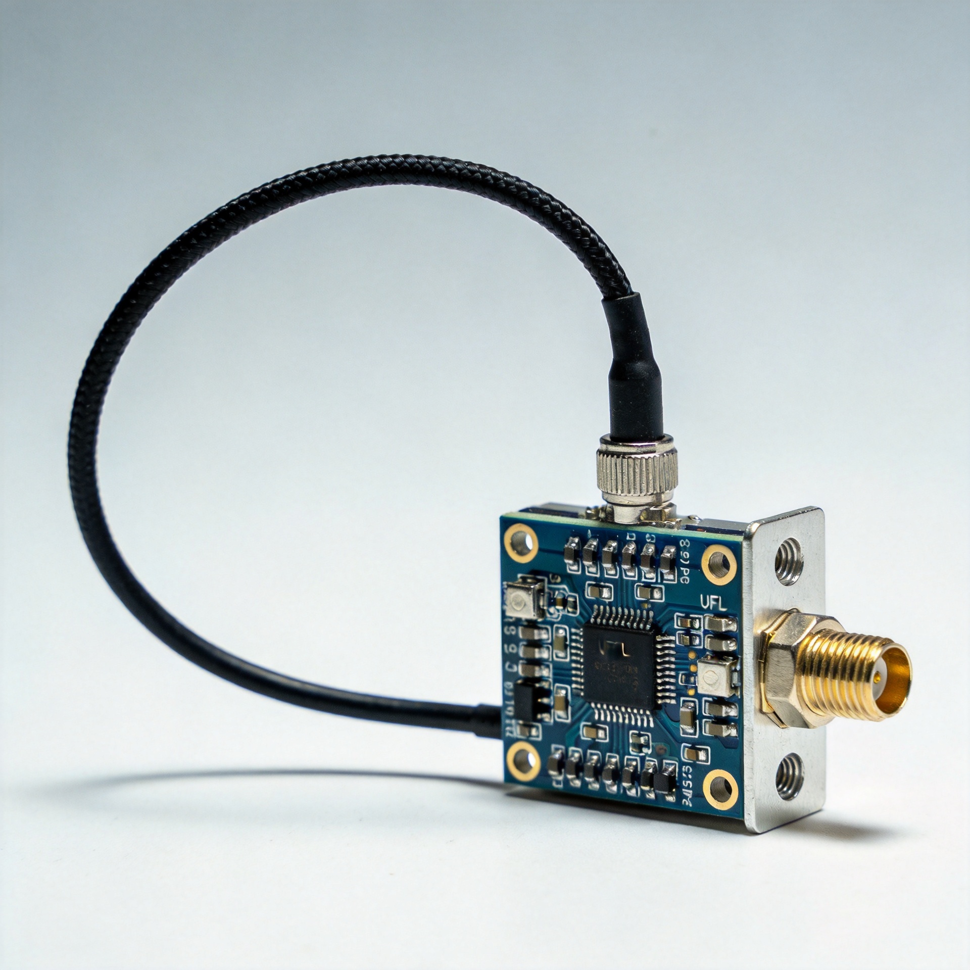
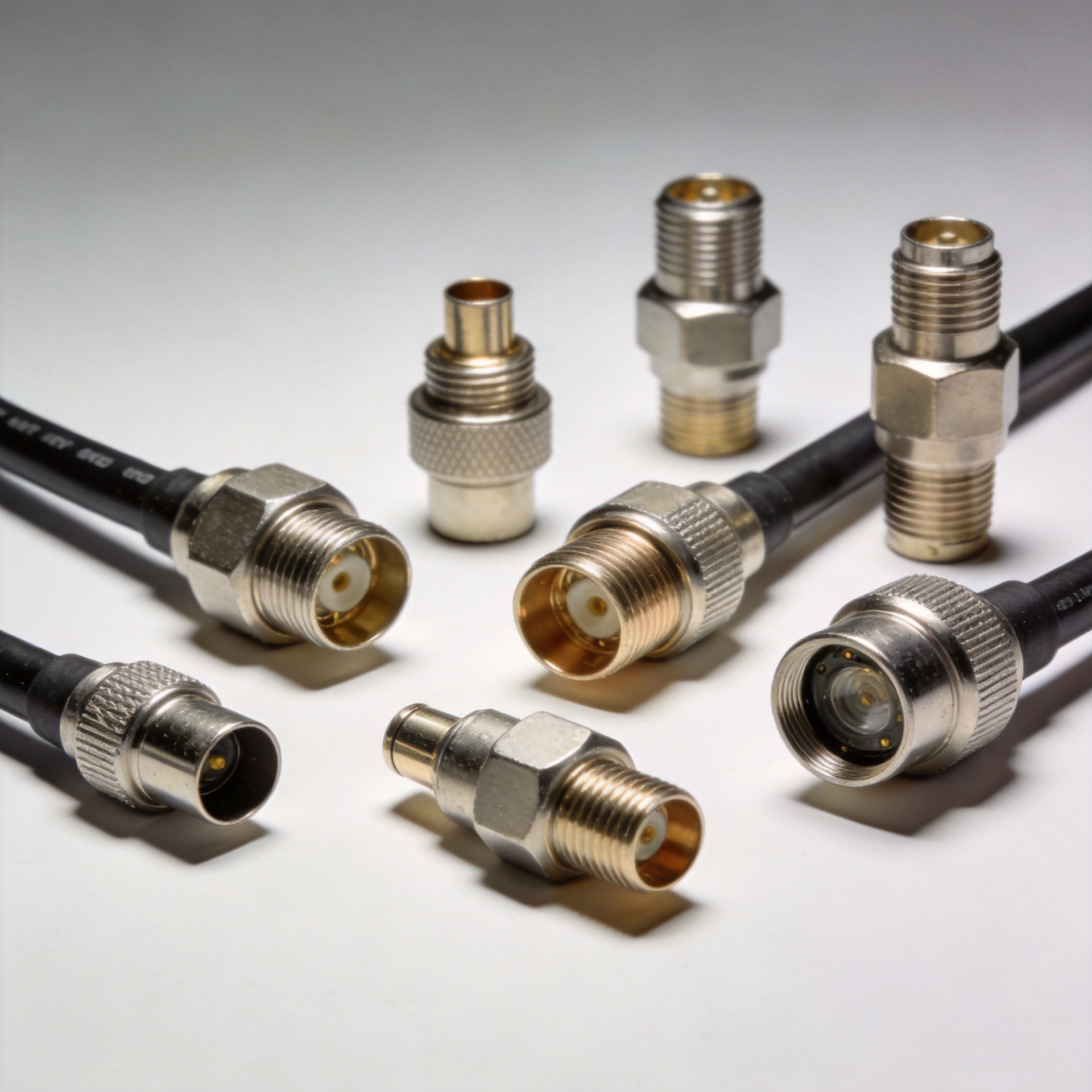
When board space is tight, the connector is not a minor mechanical detail. It is part of the RF path. An MCX connector gives engineers a compact, snap-on coaxial interface for routing and testing RF signals without moving to the smallest connector families immediately. For antenna modules, radio boards, GPS equipment, compact instruments, and cable assemblies, understanding where an MCX connector fits can prevent a mismatch between the drawing, the cable, and the electrical target.
This introduction takes an application-first view. Instead of treating every MCX connector as interchangeable, it explains the size position of MCX, how it compares with an MMCX connector, and which specification checks matter before a part is released to a bill of materials.
What Is an MCX Connector?
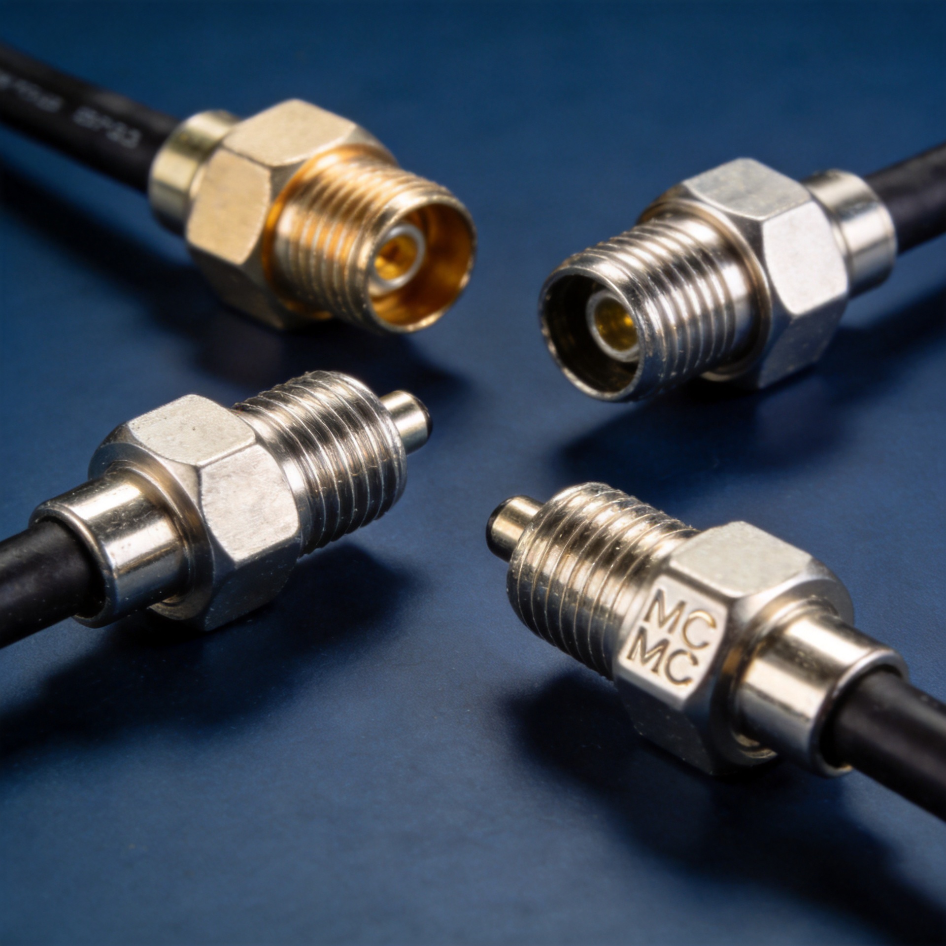
An MCX connector is a miniature RF coaxial connector family that typically uses a snap-on coupling interface. The coupling lets an operator push the plug into place rather than thread a nut, which can speed assembly where access is limited. Many MCX connector series are built around a 50-ohm RF system, and engineers should verify the impedance and mating interface on the exact manufacturer drawing.
The family is often used when a full-size threaded connector would take too much room or make repeated connections slow. It is not simply a smaller SMA connector: the coupling method, mechanical retention, available cable terminations, and performance limits must all be assessed as a system.
Published product references commonly place standard MCX connector offerings in the DC-to-6-GHz range. Some manufacturer-specific 50-ohm series are rated beyond that range, so “MCX” alone is not an electrical rating. The applicable datasheet, cable type, mounting style, and test conditions define the usable limit for a real assembly.
Why Compact RF Designs Use MCX
Compact RF equipment often has competing requirements: preserve coaxial signal integrity, leave room for active circuitry, and allow production or service teams to make connections quickly. The MCX connector is useful because it balances a relatively small package with a familiar coaxial construction and a fast snap-on action.
- Space efficiency: The miniature form factor suits dense boards, compact housings, and short RF cable runs.
- Fast mating: Snap-on coupling can be practical for test fixtures, internal links, and locations where a threaded coupling is inconvenient.
- Application flexibility: Cable plugs, panel interfaces, and PCB-mounted versions allow the RF transition to be planned around the enclosure and assembly sequence.
- Controlled interface: With a matched 50-ohm connector and cable system, the assembly can be designed around the impedance used by much RF equipment.
These benefits do not remove the need for mechanical review. A snap-on connection is convenient, but the expected vibration, cable pull, mating frequency, and available clearance still determine whether it is the right choice.
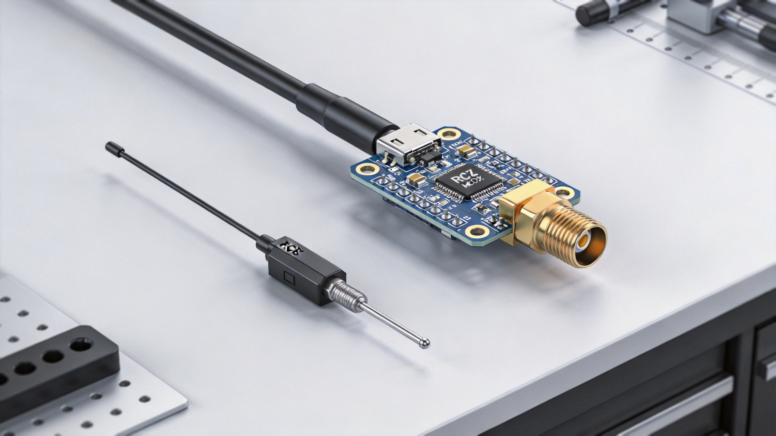
MCX Connector vs. MMCX Connector: Start with the Physical Envelope
The MCX connector and the MMCX connector are both compact snap-on RF families, which is why they are often considered together. The practical distinction begins with size. MMCX is the more microminiature option, usually chosen when the PCB or device enclosure has even less room. MCX provides a slightly larger interface that can be easier to handle in many compact assemblies.
| Selection question | MCX connector | MMCX connector |
|---|---|---|
| Relative package size | Miniature | Microminiature; generally smaller |
| Coupling approach | Typically snap-on | Typically snap-on |
| Typical use case | Compact RF boards, instruments, antennas, cable assemblies | Very space-constrained modules and small devices |
| What to validate | Series impedance, frequency, retention, cable compatibility | Same checks, with added attention to handling and cable strain relief |
Do not select by size alone. MCX and MMCX interfaces are not mating substitutes. A purchasing description should specify the family, gender or interface style, mounting/termination type, impedance, cable designation where applicable, and the manufacturer part number or controlled drawing.
Common MCX Connector Applications
An MCX connector appears where a compact coaxial interface is needed but the application still benefits from a serviceable or modular connection. Examples include GPS and GNSS antenna paths, communications equipment, RF test instruments, wireless modules, broadcast-related equipment, and internal coaxial links in industrial electronics.
For an antenna lead, the critical question is not only whether the MCX connector fits the enclosure. The designer should review the cable bend radius, connector orientation, ground return, environmental exposure, and the frequency behavior of the complete path. For a board-mounted interface, pad geometry, launch design, and panel alignment can be as influential as the connector family name.
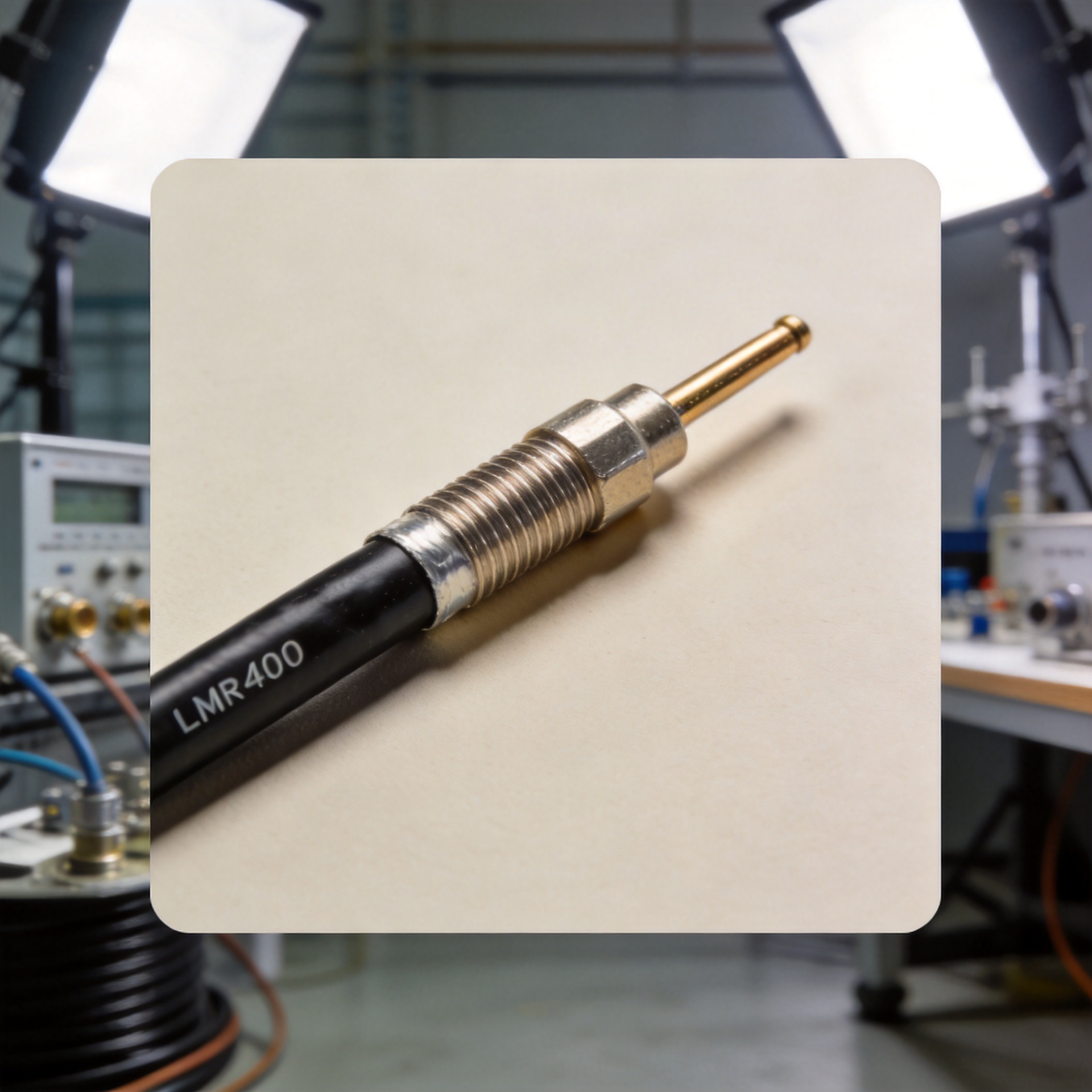
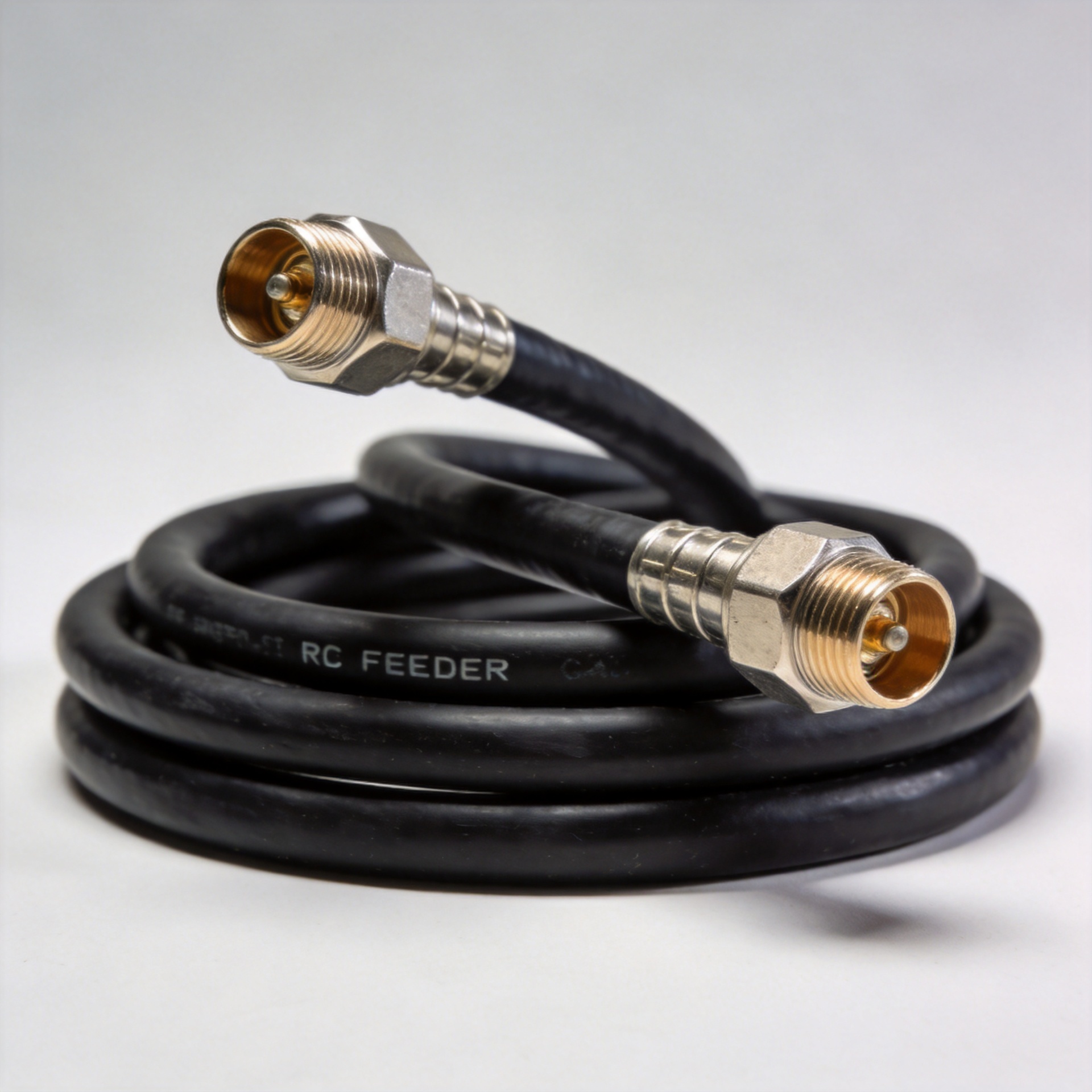
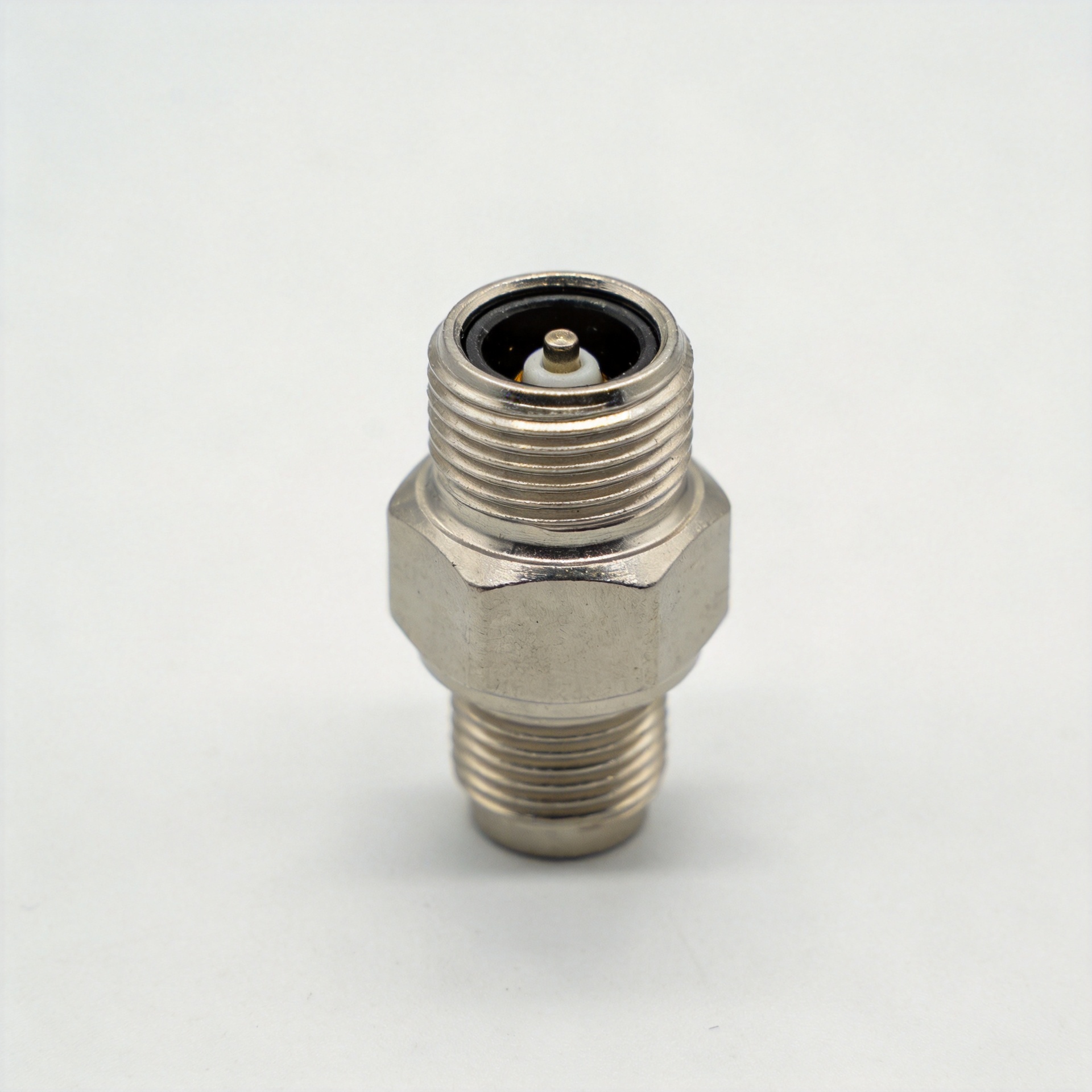
Teams sourcing several RF interconnect items may also benefit from reviewing the connector, cable, and termination together. For example, a catalog item such as a factory-price RF N female connector for RG58, 3D-FB, LMR195, and LMR200 cable illustrates why connector selection is tied to cable construction and installation context. It is a different connector family from MCX, so it should not be treated as an MCX substitute; it is relevant here as a reminder to confirm cable and interface compatibility across the RF interconnect BOM.
A Practical MCX Connector Selection Checklist
- Confirm the interface family: Specify MCX explicitly. Do not rely on a photo or a generic “mini RF connector” description.
- Match impedance end to end: Verify whether the selected MCX connector, cable, PCB launch, and connected equipment are intended for the same impedance system.
- Check the required frequency range: Use the exact series datasheet. A commonly quoted upper frequency is not a substitute for the rating of the chosen part.
- Choose the termination correctly: PCB, panel, bulkhead, crimp, and cable-mount designs have different assembly and inspection needs.
- Review orientation and clearance: Straight and right-angle configurations affect cable routing, lid clearance, and strain on the connection.
- Evaluate the mechanical environment: Consider vibration, handling, pull force, expected mating cycles, and whether a snap-on interface needs additional retention in the enclosure.
- Control the mating pair: Confirm the mating interface with drawings and samples before volume procurement, especially if components come from different sources.
Specification Details That Deserve a Datasheet Check
An awareness-stage discussion should make one point clear: an MCX connector is a family name, not a complete specification. Before qualifying a part, engineers and buyers should inspect the product documentation for characteristic impedance, operating frequency, VSWR or return-loss limits, dielectric withstand voltage where relevant, contact material and plating, temperature range, mating durability, and recommended cable or PCB layout.
For high-frequency work, return loss and launch quality matter as much as the nominal frequency headline. A connector rated for a given band can still deliver poor system results when it is paired with an unsuitable cable, a poorly controlled board transition, or an overstressed right-angle installation. Likewise, a fast snap-on coupling should be evaluated against the real retention requirement rather than assumed to be adequate for every mobile or high-vibration installation.
Installation Notes for More Reliable RF Assemblies
Start with the assembly process, not only the component list. If the MCX connector is crimped, use the approved cable preparation dimensions and tooling. If it is board-mounted, follow the footprint and soldering guidance from the selected series. Avoid twisting the cable directly behind the termination and leave enough service loop for panel removal where possible.
During prototype validation, inspect both electrical and mechanical behavior. A simple continuity check is not enough for a path that carries RF energy. Depending on the application, verify insertion loss, return loss, repeatability after mating cycles, and performance after the relevant temperature or vibration exposure. These checks turn an apparently compatible MCX connector into a controlled interconnect decision.
Key Takeaway
An MCX connector is a practical compact RF interface when a snap-on coaxial connection, controlled impedance, and manageable assembly size are required. It is often a sensible middle ground between larger RF interfaces and the smaller MMCX connector family. Define the required frequency, impedance, cable, mounting method, and mechanical environment first; then use the exact supplier datasheet to select and validate the mating pair. That process is more reliable than choosing solely by connector size or a generic frequency claim.