EN

RF Power Divider Types: Wilkinson, Resistive and Hybrid Designs
Choosing RF power dividers is not simply a matter of splitting one signal into two. The topology determines how much power is lost, whether the output ports interact, what phase relationship is preserved, and how wide a frequency range the assembly can support. For an RF systems engineer, the useful starting point is the signal path and the application requirement—not a catalog filter alone.
This article compares three common families of RF power dividers: Wilkinson designs, resistive designs, and hybrid couplers used as dividers. Each answers a different engineering problem. A two-way cellular distribution path, a measurement fixture, and a phase-sensitive antenna feed may all require RF power dividers, but they should not automatically use the same topology.
What to establish before comparing RF power dividers
Start with the operating band, system impedance, number of outputs, allowable insertion-loss budget, input power, connector interface, and required phase relationship. Then ask whether one output may see a changing load. That last question is important because the isolation of RF power dividers determines how strongly a mismatch on one branch can influence another branch.
For most telecom and test systems, 50 ohms is the expected reference impedance. However, the device must match the entire assembly, including cables, antennas, loads, and connectors. The lowest insertion-loss figure is not the whole story. Return loss, amplitude balance, phase balance, power handling, and environmental suitability can be more decisive than a marginal loss difference.
Wilkinson RF power dividers: efficient in-phase splitting
A Wilkinson divider is usually the first choice when an equal, in-phase split and output isolation are both important. In the conventional two-way equal-split form, it uses two quarter-wave transmission-line branches and an isolation resistor between the output ports. At the design frequency, the familiar theoretical arrangement uses branch impedances of approximately 1.414 times the system impedance and a resistor of 2Z0. This structure lets Wilkinson RF power dividers provide good matching and isolation while avoiding the intentional resistive dissipation of a basic resistive splitter under balanced conditions.
The trade-off is bandwidth and physical implementation. Quarter-wave sections are frequency dependent, so a simple single-section design is most appropriately treated as a centered-band solution rather than a universal broadband component. Multi-section implementations can broaden the useful band, but they add complexity, size, and tolerance sensitivity. When comparing Wilkinson RF power dividers, verify the specified frequency range, isolation, VSWR or return loss, amplitude balance, phase balance, and power rating at the frequencies that matter to the actual system.
Wilkinson designs fit antenna distribution, balanced receiver paths, and laboratory signal splitting where outputs should remain in phase. They are less compelling when DC coverage or exceptionally wide bandwidth outweighs efficiency and isolation.
Resistive RF power dividers: simple and broad-band, with a loss penalty
Resistive RF power dividers use resistor networks rather than transmission-line transformations. Their practical advantage is broad operating bandwidth; some arrangements can cover from DC upward, making them useful when a transmission-line divider would be too narrow-band. They are compact and straightforward, which can also make them useful in instrumentation and low-power signal-conditioning paths.
The cost is dissipative loss. A resistor network converts a material part of the input power into heat even when loads are matched, so it is not the efficiency-first answer for a power-sensitive distribution network. As a useful reference point, an ideal three-port resistive splitter is often described with roughly 6.02 dB transmission loss from one port to another; the exact result depends on the circuit and port count. Do not compare that number directly with an ideal 3 dB equal split without accounting for the topology’s added dissipation.
Some readers loosely call all resistor-based configurations “isolated.” That is not a safe shortcut. Check the manufacturer’s S-parameter data for the actual resistive RF power dividers under consideration. If output-to-output isolation, mismatch behavior, or reverse power is critical, the complete network and rated conditions matter more than the generic label.
Hybrid RF power dividers: select them when phase is part of the requirement
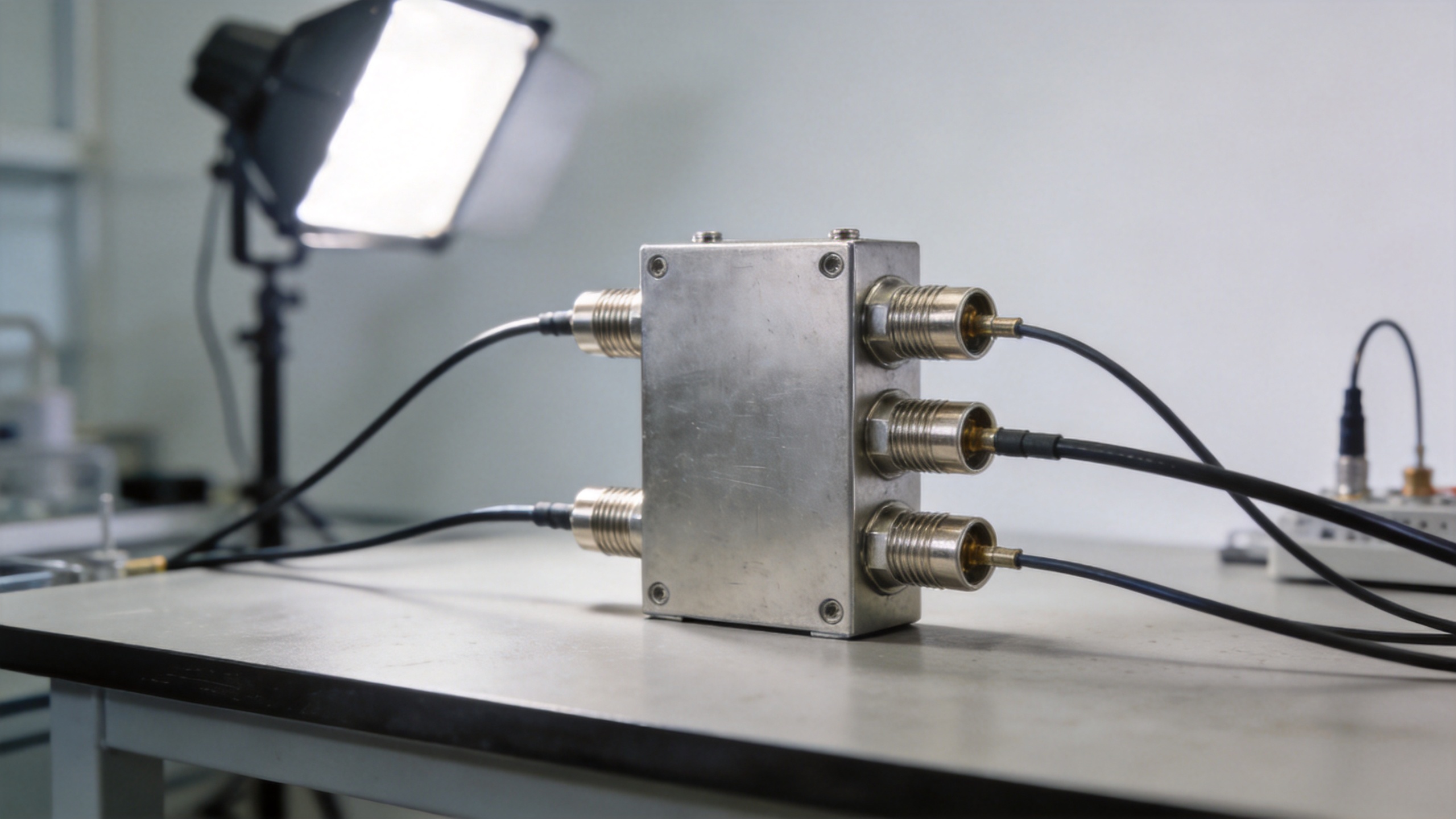
Hybrid couplers can perform a power-splitting function, but their main distinction is a defined phase relationship between outputs. A quadrature hybrid commonly produces equal outputs with a 90-degree phase difference; other hybrid forms may provide 180 degrees or another defined relationship. This makes hybrid RF power dividers appropriate for balanced amplifiers, IQ-related signal paths, feed networks, and designs where phase control is intentional rather than incidental.
Do not treat a hybrid as a drop-in substitute for an in-phase Wilkinson divider. Both can divide power, but the phase behavior, port assignment, and termination requirements differ. In a hybrid, the isolated port must be treated correctly for the expected performance. Review the phase convention, amplitude balance, isolation, return loss, frequency band, and whether the intended use is division, combination, or both before selecting hybrid RF power dividers.
A practical selection table
| Topology | Best fit | Main strength | Key caution |
|---|---|---|---|
| Wilkinson | In-phase equal splitting | Good matching and output isolation around its design band | Frequency-dependent transmission-line design |
| Resistive | Broad-band or DC-to-RF signal paths | Simple, compact topology | Intentional dissipative loss |
| Hybrid | Phase-controlled distribution | Defined output phase relationship | Port convention and termination must be respected |
Treat the table as a first filter rather than a final specification. A higher frequency rating is not automatically better if the extra margin is outside the operating plan and forces unnecessary cost or packaging compromises. Likewise, optimizing only insertion loss can overlook return loss and isolation, which may have a larger effect on a real multi-branch RF path.
How to specify RF power dividers for a connectorized deployment
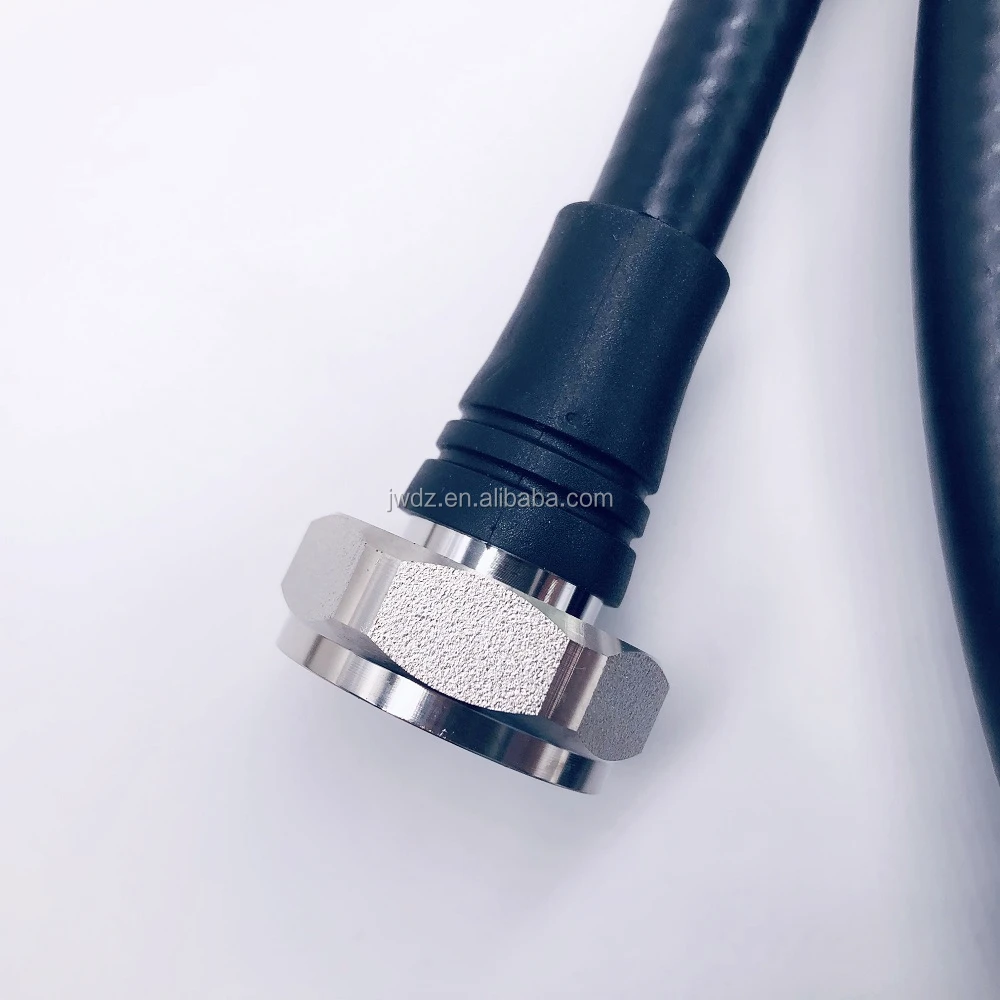
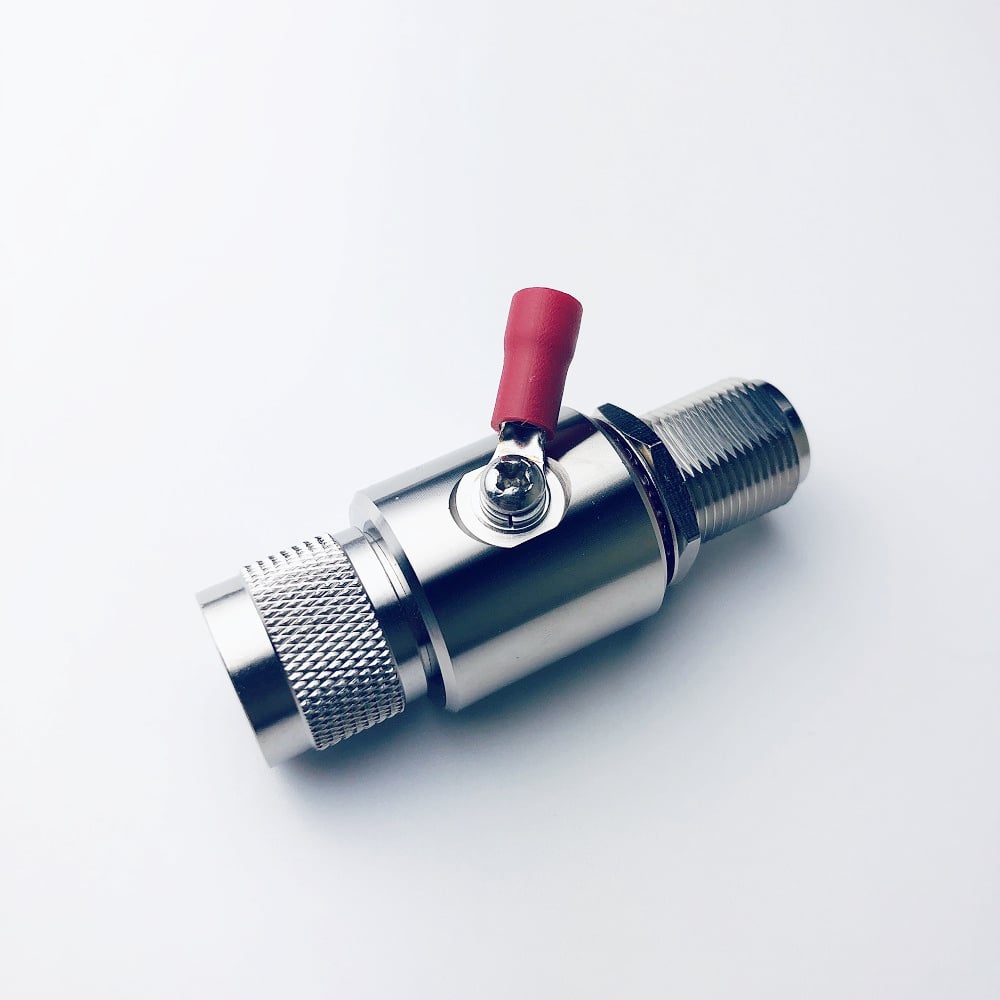
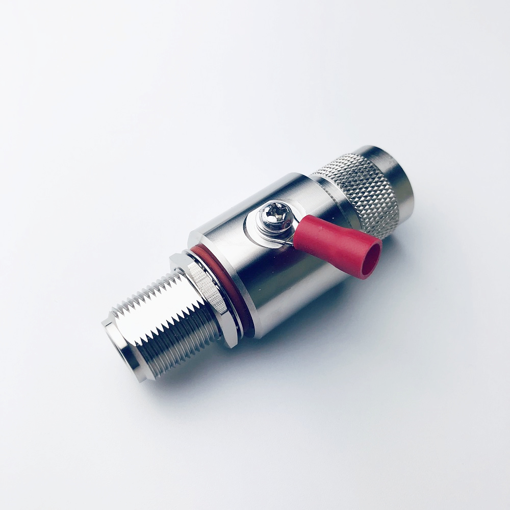
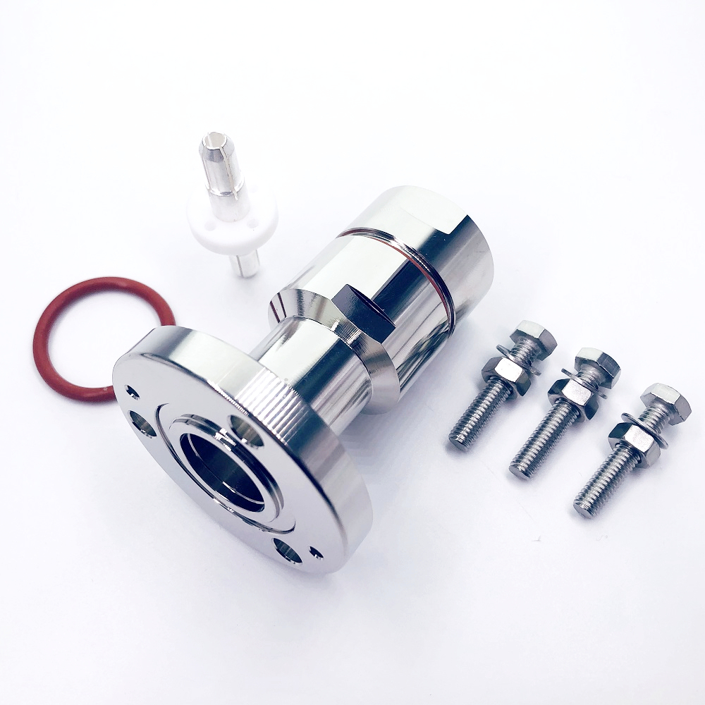
Build the RFQ around measurable requirements: frequency band, impedance, split ratio, output phase, insertion loss, isolation, input and reverse-power limits, VSWR or return loss, amplitude and phase balance, connector type, mechanical outline, and environmental conditions. For outdoor or telecom installations, also confirm cable mating compatibility, torque practices, sealing approach, and the service-access requirement. A technically strong divider can still create a poor assembly if its connector interface does not fit the cable and maintenance plan.
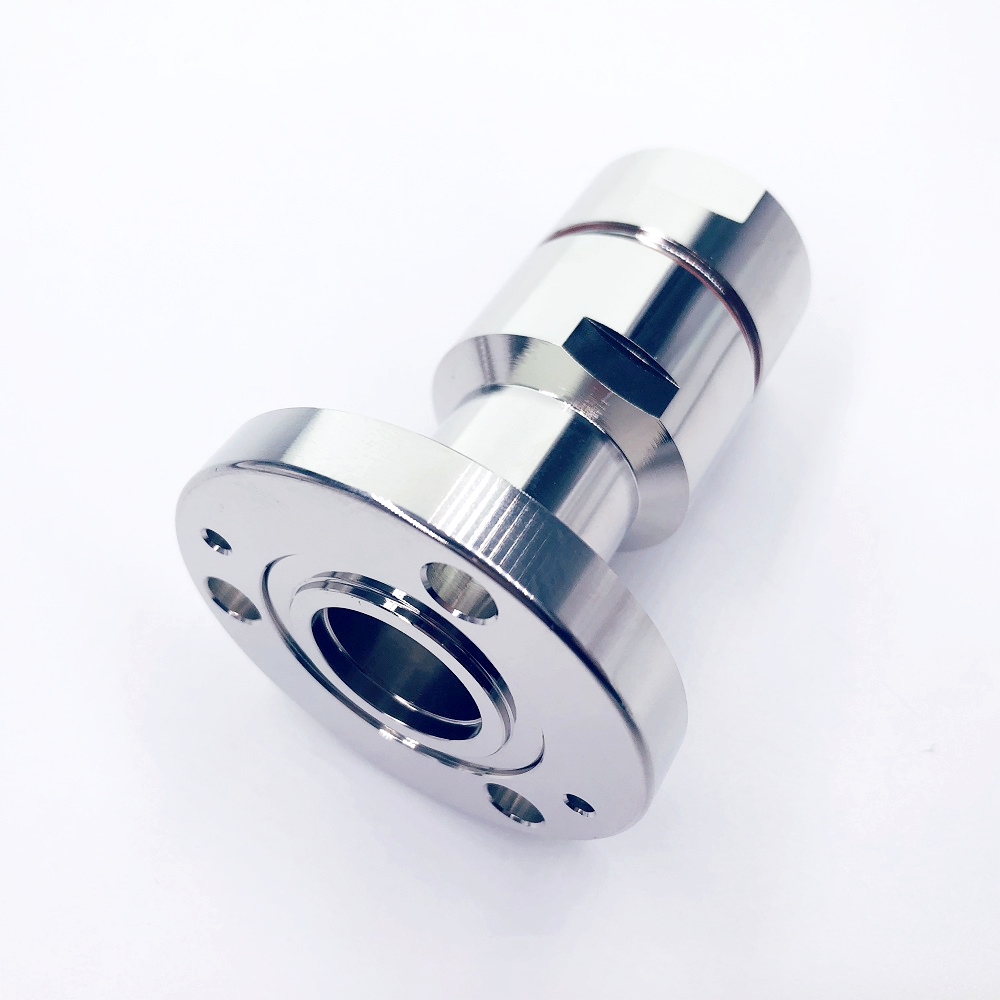
When a connectorized two-way part is needed in the 698–3800 MHz range, review the actual drawing and electrical data for the DIN 7/16 Female Low PIM 698–3800 MHz 2-Way Power Divider Power Splitter alongside the system’s frequency, connector, and low-PIM requirements. The product title establishes the cataloged band and interface; final selection should still rely on the current product specification and deployment conditions.
Conclusion: choose the topology that protects the system requirement
The right RF power dividers are selected by function, not by name alone. Use a Wilkinson design when efficient in-phase splitting and isolation are central. Use a resistive design when bandwidth simplicity is more valuable than power efficiency. Use a hybrid when a controlled phase difference is part of the architecture. Once that choice is made, validate the complete specification against the real frequency plan, loads, connectors, and installation conditions. That is how RF power dividers become dependable parts of an RF system rather than an avoidable source of mismatch, loss, or phase error.