EN

SMA Connector vs RP-SMA Connector: Key Differences
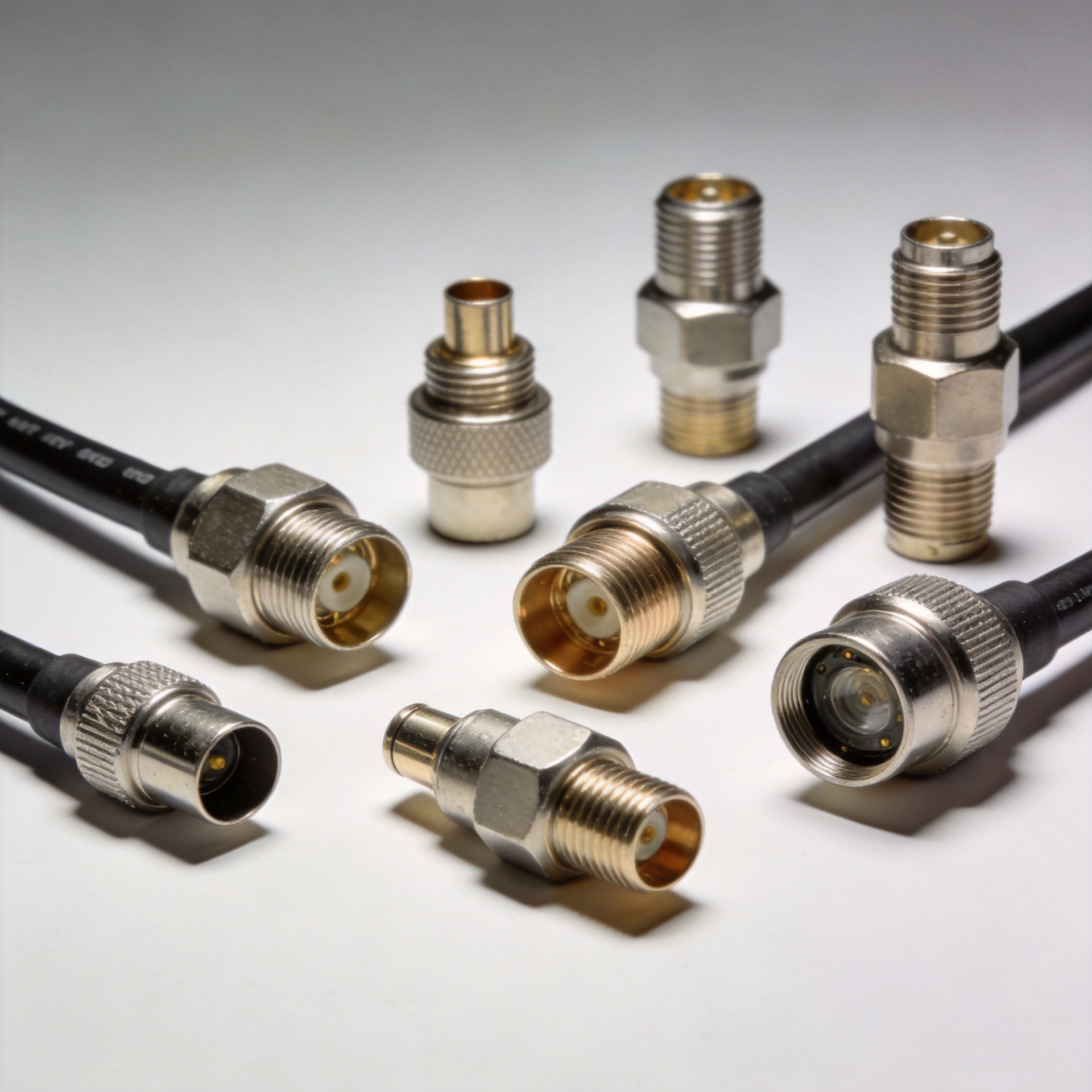
A RP SMA connector can look almost identical to a standard SMA connector from the outside. Both use a compact threaded coupling and are widely found on RF cables, antennas, wireless equipment, and test assemblies. Yet a small difference at the center contact makes the two interfaces mechanically incompatible in their standard forms. For purchasing teams, installers, and cable-assembly engineers, that distinction matters: a connector that appears to fit may not mate correctly, and forcing it can damage the interface.
This guide explains the structural difference between SMA and RP-SMA, how to identify each gender correctly, and how to verify an interface before ordering an antenna, adapter, bulkhead, or sma rf connector cable assembly.
The short answer: the center contact is reversed
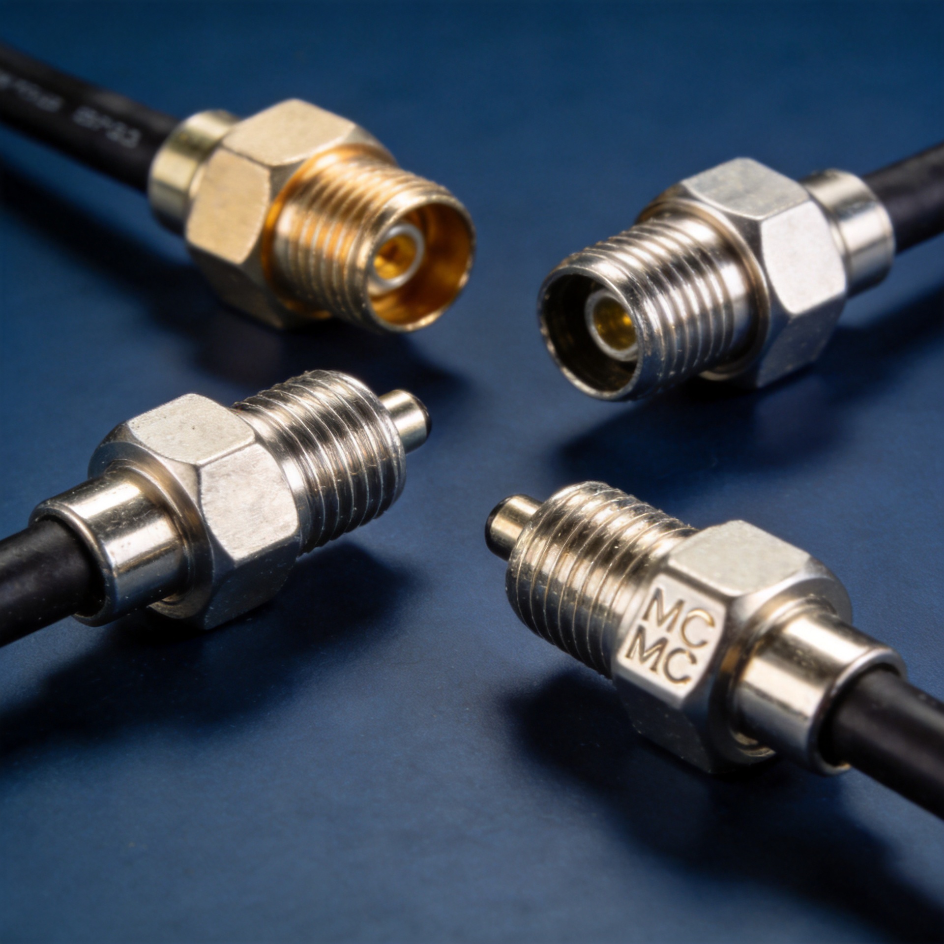
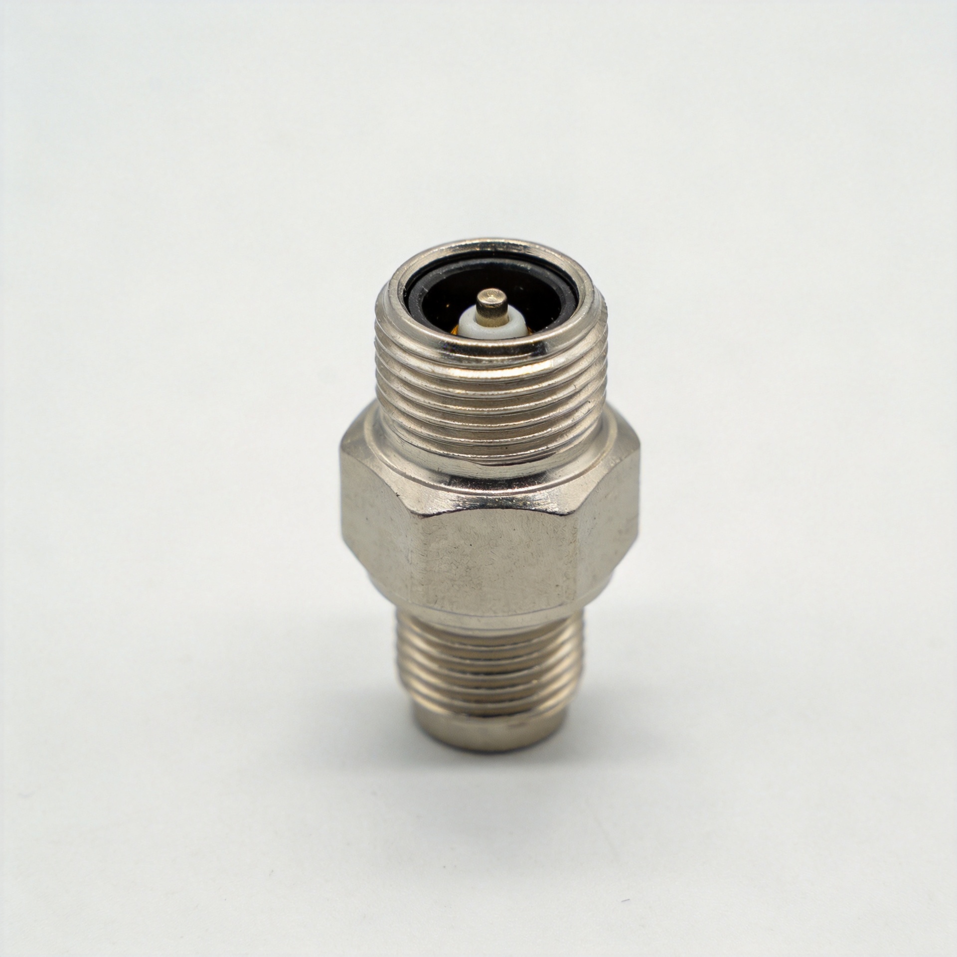
The defining feature of a RP SMA connector is reverse polarity at the center contact. In a standard SMA pair, the connector commonly described as SMA male has a center pin and an internally threaded coupling nut. The SMA female counterpart has a center socket and external threads. With RP-SMA, the threaded outer geometry still follows the familiar mating pattern, but the center contact assignment is swapped.
As a result, an RP-SMA male typically has a center socket rather than a pin, while an RP-SMA female typically has a center pin rather than a socket. This is why thread inspection alone is not enough. The outer coupling can look familiar, but the center-contact geometry determines whether the mating pair is actually correct.
SMA vs RP-SMA: a practical comparison
| Feature | Standard SMA | RP-SMA |
|---|---|---|
| Outer coupling | Threaded RF coupling | Similar threaded RF coupling |
| Key difference | Conventional center pin/socket assignment | Center pin/socket assignment is reversed |
| Visual check | Confirm center pin or socket with thread type | Confirm reversed center contact with thread type |
| Direct compatibility | Mates with the corresponding SMA counterpart | Mates with the corresponding RP-SMA counterpart |
| Typical use | RF and microwave assemblies, instrumentation, antennas | Wireless networking antennas, routers, access points, and RF leads |
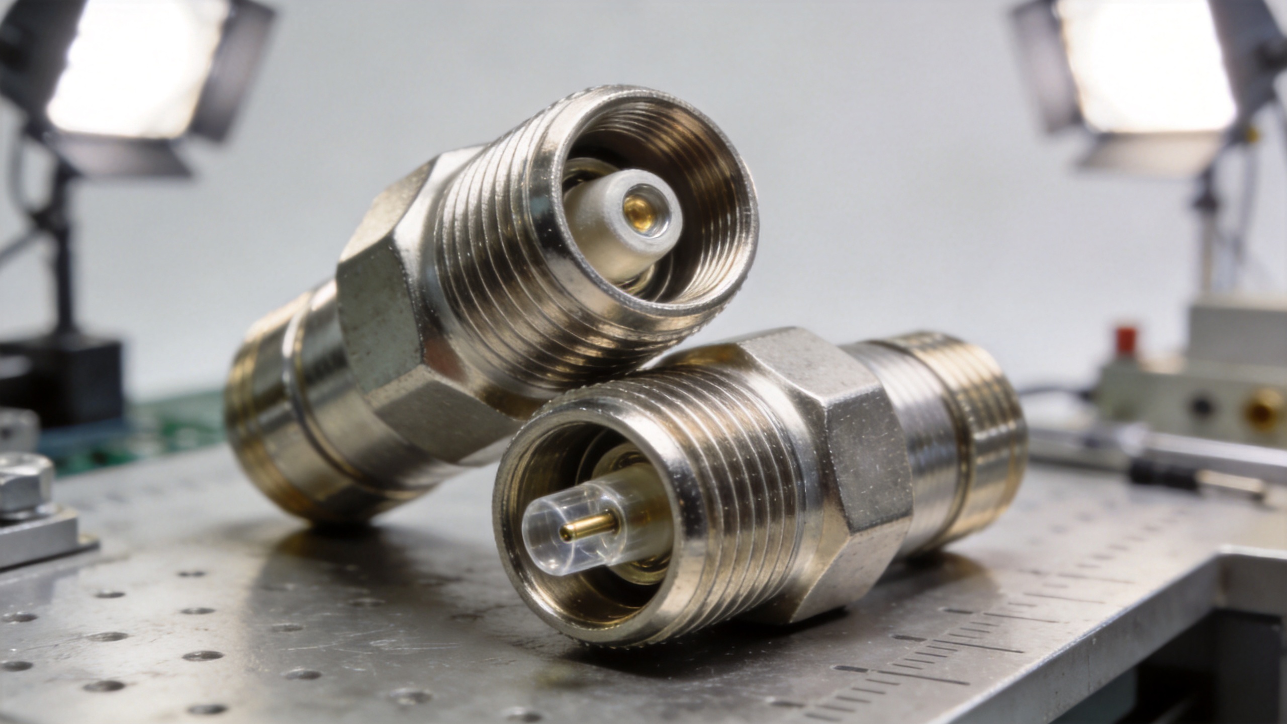
Both connector families are commonly used in 50-ohm RF systems. However, impedance class alone does not make two connectors interchangeable. The exact connector series, gender convention, cable termination, frequency requirement, and mating interface must all be verified in the drawing or datasheet.
Why the naming causes mistakes
The labels “male” and “female” are often interpreted only through the thread. That shortcut is the source of many ordering errors. With an rp sma connector, the thread designation and the center-contact designation must be read together. For example, seeing a coupling nut does not automatically tell you whether the assembly is standard SMA male or RP-SMA male; inspect the center contact as well.
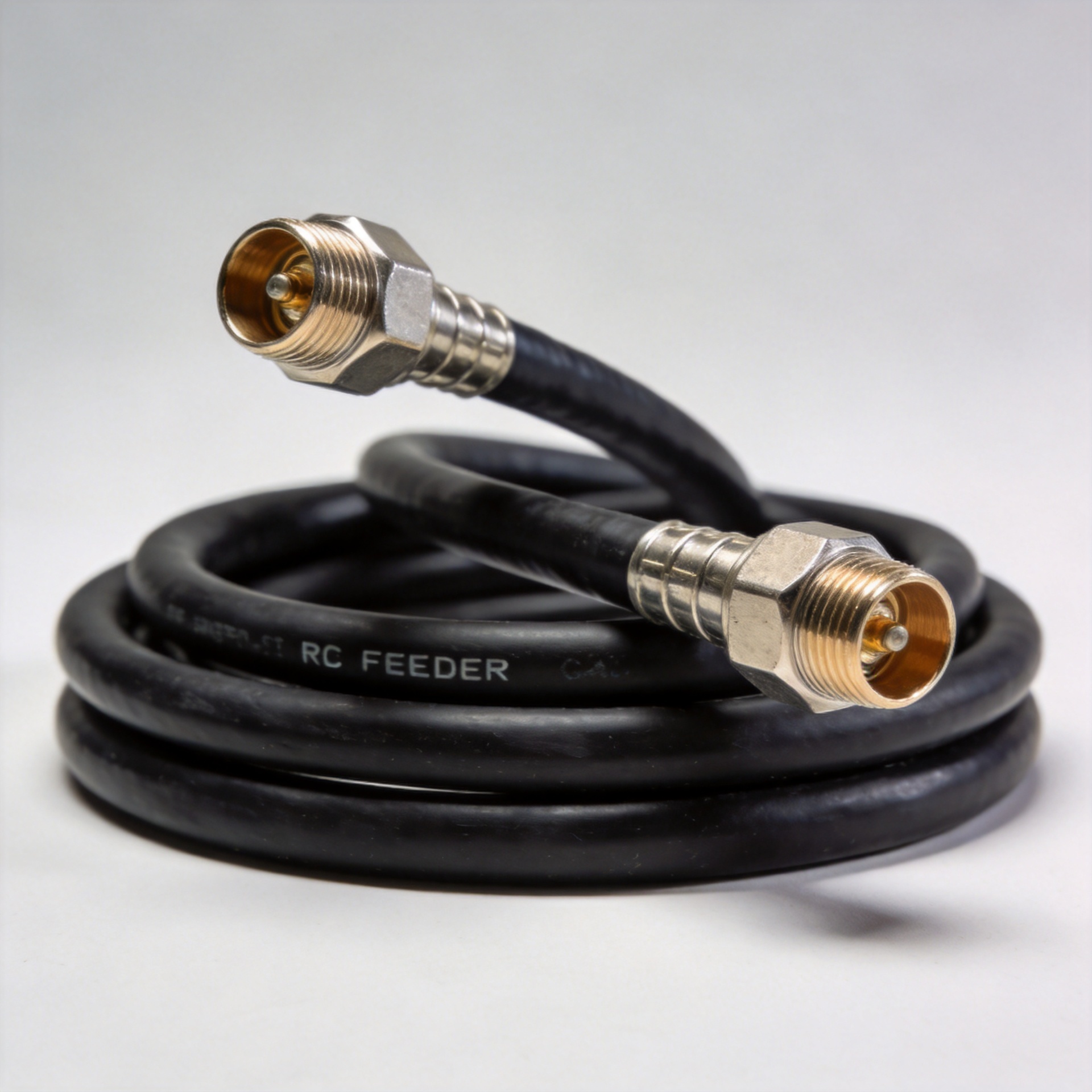
A reliable habit is to describe the complete interface in a purchase request: series, polarity, gender, body style, termination method, cable type, and any required electrical limit. “SMA antenna cable” is too broad for a production order. “RP-SMA male to RP-SMA female, 50 ohm, right-angle to bulkhead, for specified coax” is much less ambiguous.
How to identify the connector before you mate it
- Check the center contact first. Look for a projecting pin or a receiving socket. This is the quickest way to separate standard SMA from reverse-polarity SMA when the outer form looks similar.
- Then inspect the threads. Note whether the coupling interface has internal or external threads. Pair this observation with the center contact rather than using it alone.
- Read the equipment label and drawing. Antenna ports, cable drawings, and product datasheets may state SMA or RP-SMA explicitly. If the label is absent, request a mechanical drawing or close-up photograph from the supplier.
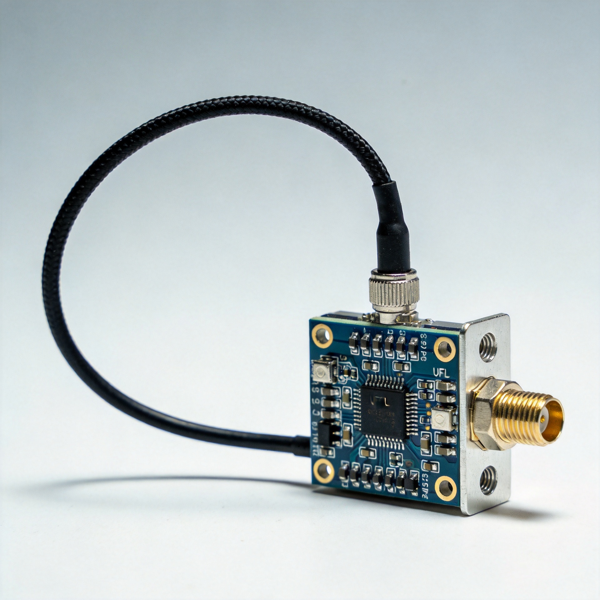
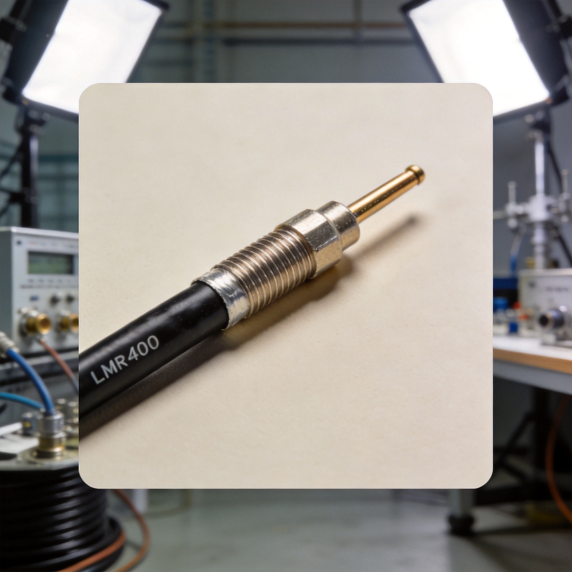
- Confirm the cable and termination. A correct sma rf connector interface can still be unsuitable if the cable diameter, crimp die, solder method, or strain-relief design does not match the requested assembly.
- Use an adapter deliberately. An SMA-to-RP-SMA adapter can solve a verified interface mismatch, but it should not replace early specification control. Additional interfaces add another item to inspect in an RF path.
Common applications for each interface
Standard SMA remains common in RF and microwave interconnects, laboratory setups, radio equipment, and many antenna or cable assemblies. RP-SMA is especially familiar in WiFi and other wireless-networking hardware, where antenna ports and extension leads often use reverse-polarity formats. Actual usage varies by manufacturer and equipment generation, so application category is a useful clue—not proof of compatibility.
For OEMs and integrators, the key question is not which style is universally better. It is which RP SMA connector or SMA interface matches the existing port, the selected antenna, and the intended cable assembly. A correct match supports consistent assembly work and avoids avoidable rework during installation.
A procurement checklist for SMA and RP-SMA assemblies
- State SMA or RP-SMA explicitly; do not rely on a product photo alone.
- Specify both the outer-thread orientation and center pin/socket configuration.
- Confirm the required impedance and the applicable frequency range from the product documentation.
- Match the connector termination to the exact coaxial cable type and outside diameter.
- Verify body style: straight, right-angle, panel-mount, bulkhead, or cable-mounted.
- Request a drawing, sample, or photo confirmation before volume production when a port is difficult to inspect.
RP SMA connector questions buyers should ask
Is the rp sma connector on the device a pin or a socket at the center contact? Is the mating cable specified as the complementary rp sma connector type? These two checks should appear on every purchase request.
Does the requested rp sma connector use a straight, right-angle, bulkhead, or panel-mount body? Does the rp sma connector termination match the coaxial cable actually being used? Body style and cable fit are separate decisions from polarity.
For a replacement assembly, compare the existing port and the new rp sma connector side by side. A photograph of the center contact can help a supplier confirm the rp sma connector configuration before production.
When an antenna is involved, verify the antenna-side rp sma connector and the equipment-side interface independently. An extension lead may have a different rp sma connector combination at each end.
For field-service stock, label bags with the full rp sma connector description rather than “SMA.” Clear labels keep a standard SMA part from being mixed with an rp sma connector part.
For approval samples, request the drawing and cable specification for each rp sma connector assembly. The drawing should show the center contact, thread form, and termination; this is more reliable than judging a rp sma connector from its overall silhouette.
A qualified rp sma connector supplier can also help confirm cable compatibility, but the final assembly requirement should remain in the buyer’s controlled specification. Record the accepted rp sma connector configuration in the BOM and inspection criteria.
If an adapter is necessary, specify both sides of the adapter: the incoming rp sma connector interface and the outgoing SMA or rp sma connector interface. This avoids ordering an adapter that repeats the original mismatch.
Before shipment, a simple visual check of each rp sma connector can catch mixed lots. Review the center-contact geometry, the coupling thread, and the order label together.
Final takeaway
The difference between SMA and RP-SMA is small in appearance but decisive in use: RP-SMA reverses the center contact relative to standard SMA. Before purchasing or connecting any RF assembly, inspect both the center contact and the coupling threads, then confirm the full interface against documentation. That simple process helps buyers select the right rp sma connector, reduce mating errors, and keep RF cable and antenna assemblies consistent across a project.