EN

What Is a Distributed Antenna System and How Does It Work?
When a building has poor mobile coverage, the problem is rarely solved by simply adding one stronger antenna. Walls, floors, metalwork, and long cable runs all weaken radio signals. A DAS system, short for distributed antenna system, addresses this by taking a usable signal source and distributing it through multiple carefully located indoor antennas. The result is more consistent cellular or radio coverage in the places where people actually work, travel, or gather.
For facility teams, system integrators, and telecom equipment buyers, it helps to see a DAS system as an RF distribution network rather than a single product. The source, transport path, passive components, antennas, and installation layout all have to work together. This article explains the signal path, the main architecture choices, and the practical checks that matter before selecting indoor DAS hardware.
What is a DAS system?
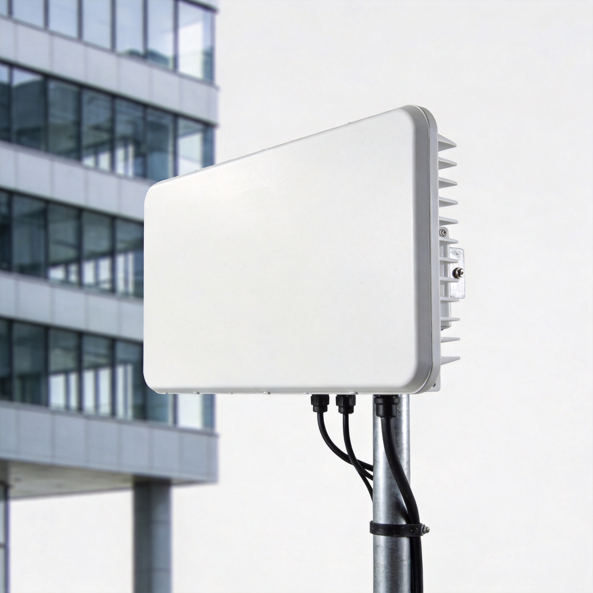
A DAS system is a network of spatially separated antenna nodes connected to a common signal source. Instead of asking one antenna to cover an entire building, it brings the signal closer to users by placing multiple antennas throughout the coverage area. Depending on the application, the system may support commercial cellular service, private radio, public-safety communications, or other wireless services designed into the project.
The goal is not merely higher signal strength in one spot. A well-designed DAS system aims for usable coverage and capacity across rooms, corridors, floors, and other occupied areas. That makes it particularly relevant in hotels, offices, hospitals, campuses, transit spaces, manufacturing facilities, and other buildings where construction materials or building geometry make outside signals unreliable indoors.
How a DAS system works: the signal path
Although equipment varies by project, the basic workflow is straightforward:
- Signal source: The system receives an approved carrier, base-station, repeater, small-cell, or radio source signal.
- Head-end processing: The signal is conditioned, combined, or amplified as required by the selected architecture.
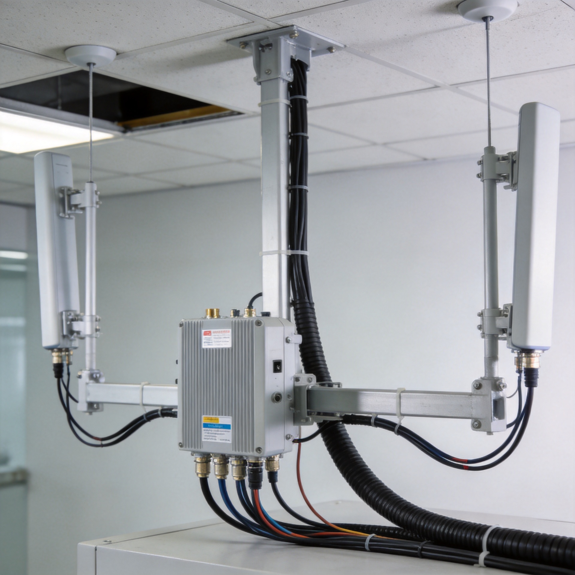
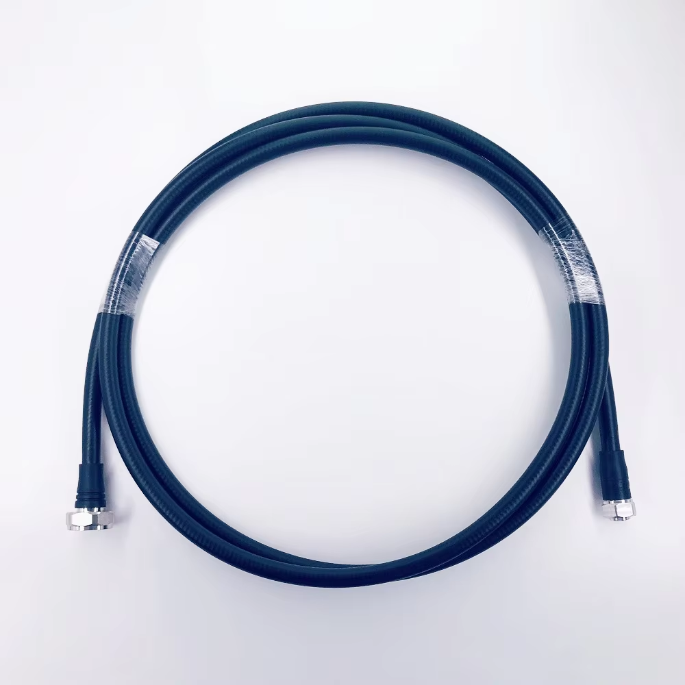
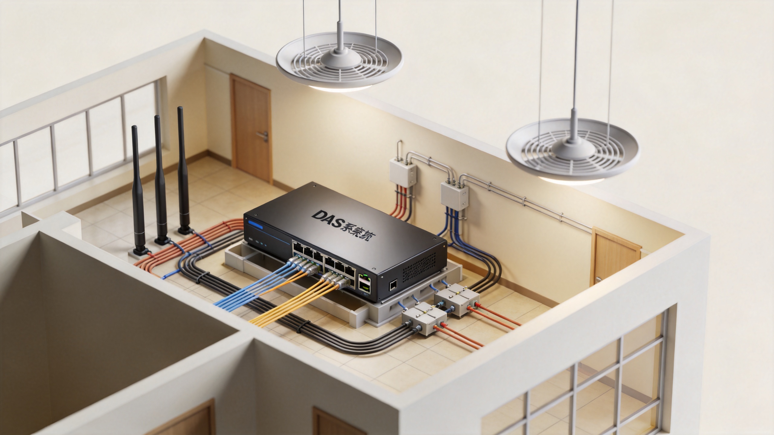
- Transport network: The signal travels through fiber, coaxial cable, or a combination of both toward the service area.
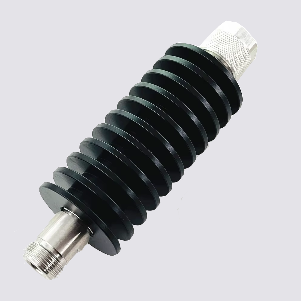
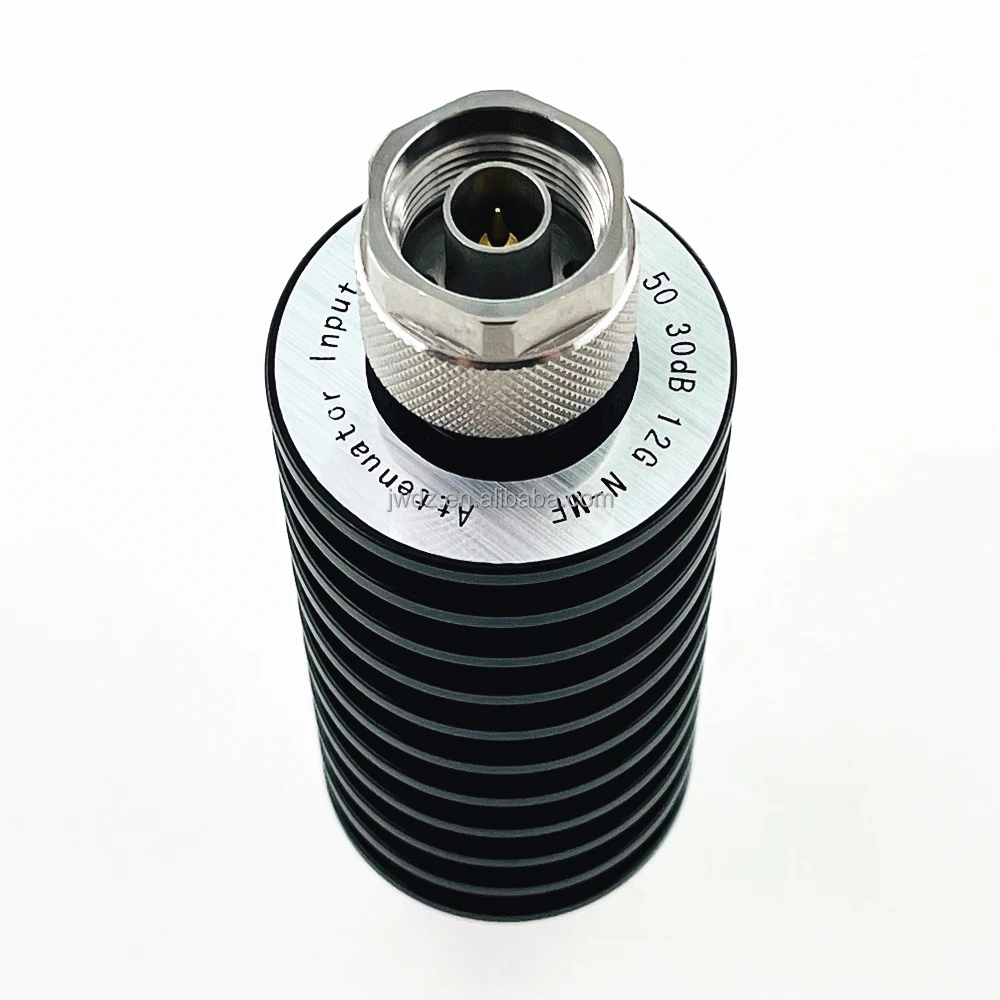
- Distribution components: Splitters, taps, couplers, and related RF hardware divide power and direct it to antenna branches.
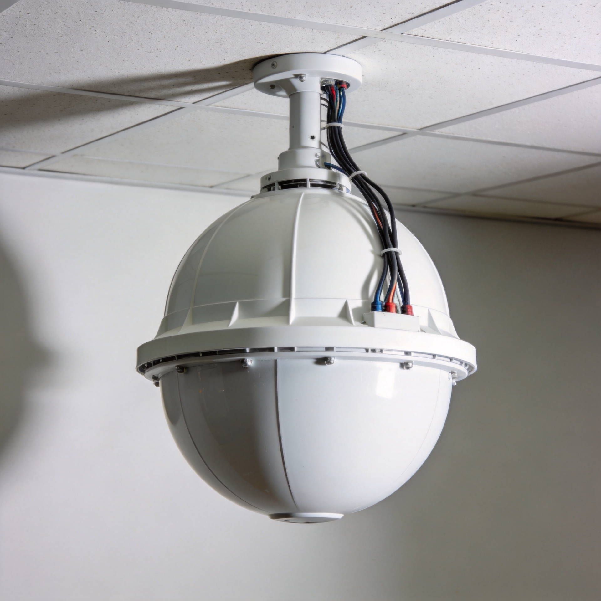
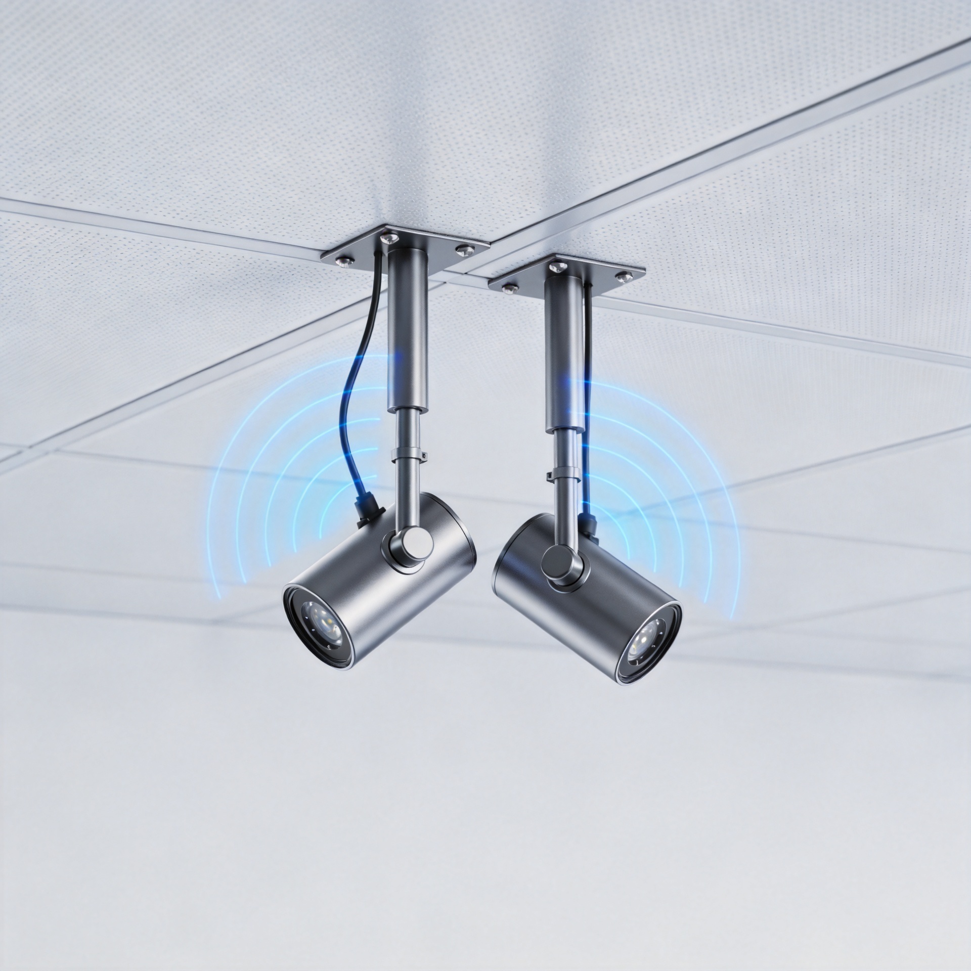
- Remote antennas: Indoor antennas radiate the signal near users, while also receiving return-path traffic back into the network.
This arrangement explains why the antenna is important but cannot be chosen in isolation. In a passive design, for example, coaxial cable, splitters, taps, and couplers are part of the RF path. Their losses accumulate, so cable lengths, branch count, and antenna placement must be considered together. In larger or more distributed projects, fiber may carry the signal over longer distances before it is converted or distributed near the antenna locations.
Passive, active, and hybrid DAS architectures
The right DAS system architecture depends on building size, signal source, required bands, coverage objectives, and the available cable routes. Three broad approaches are common:
| Architecture | Typical approach | Planning focus |
|---|---|---|
| Passive DAS | Uses coaxial cable and passive RF components to distribute signal. | RF loss budget, cable length, splitter/tap values, and antenna spacing. |
| Active DAS | Uses active equipment and often fiber-based transport to serve larger or more complex areas. | Head-end compatibility, remote-unit design, power, fiber routing, and capacity planning. |
| Hybrid DAS | Combines fiber transport with coaxial distribution near coverage zones. | Where to convert transport, how to simplify runs, and how to balance cost with coverage. |
A passive DAS system can be a practical fit for a contained indoor area when the loss budget supports the required coverage. Active or hybrid designs may be more appropriate when the facility has long distances, many floors, or multiple separated zones. These are design decisions, not labels of quality: an appropriate fit matches the RF plan and operating requirements.
Why antenna placement matters for indoor coverage
Distributed antennas are placed so the system serves real usage areas rather than just producing an attractive reading at one test point. Ceiling layout, partition density, elevator lobbies, equipment rooms, and changes in floor material can all affect coverage. A plan should therefore start with the coverage objective and a site survey, then determine antenna locations and branch routing.
Omnidirectional indoor antennas are often used where coverage should spread across a surrounding area, while directional options may help focus energy along a corridor or into a defined zone. The final choice should be based on the system design, not on antenna shape alone. It is also important to maintain installation consistency: connector workmanship, cable handling, grounding practices, and the physical environment can influence long-term RF performance.
What to check when selecting DAS antennas and RF components
For buyers assembling a DAS system bill of materials, a short specification checklist prevents many avoidable mismatches:
- Frequency coverage: Verify that the antenna and supporting components cover the bands specified for the project. Do not assume a wide-looking range fits every deployment.
- Low PIM requirements: Where the RF design calls for low passive intermodulation performance, select compatible antennas, connectors, and cable assemblies and protect them from poor installation practices.
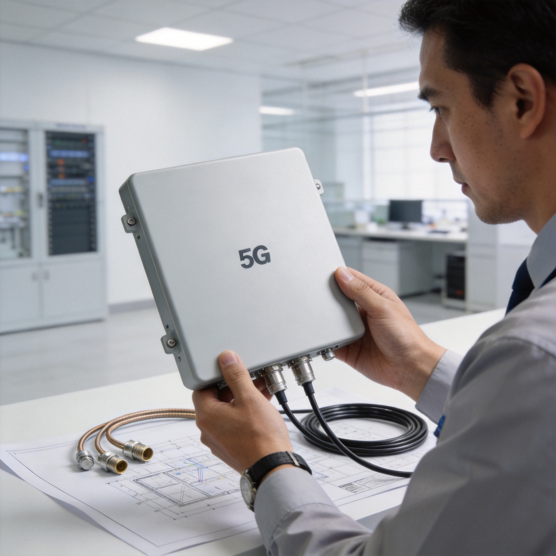
- Connector interface: Confirm the required connector type and mating arrangement across the full RF path.
- Polarization and port configuration: Check whether the design requires single-port, MIMO, or a specific polarization arrangement.
- Mounting and environment: Confirm ceiling or wall installation constraints, space, cable entry, and the relevant indoor environmental conditions.
- System compatibility: Review antenna specifications alongside cable loss, passive-component values, source power, and the design loss budget.
For example, projects needing an indoor MIMO omni antenna can evaluate a 380-6000MHz Low PIM Indoor Mimo Omni Antenna With N-Female Connector as a product category match, then verify its documented specifications against the final project design. A product title alone is not a substitute for an RF design review.
Common DAS system applications
A DAS system is used where people need dependable indoor connectivity but the building attenuates outside signals or has uneven coverage. Common examples include commercial offices, venues, hospitals, educational facilities, underground areas, transportation hubs, and industrial buildings. The design priorities vary. A venue may focus on high user density, while an industrial site may prioritize coverage through challenging layouts and coordination with existing communications infrastructure.
Awareness-stage planning should begin with a simple question: where are the weak-signal zones, and what service must work there? From there, stakeholders can define the target bands, expected coverage areas, signal source, and site constraints. This approach produces a more useful starting point than choosing individual antennas before the system requirements are known.
A practical starting point for a DAS project
Start by documenting the building zones, required wireless services, available source signal, and potential cable routes. Then have a qualified RF designer develop the link budget and antenna layout. Procurement can use that design to verify frequency range, low PIM needs, interfaces, quantities, and installation accessories across the complete bill of materials.
In short, a DAS system works by moving a usable radio signal through a planned distribution network and radiating it from multiple indoor antenna points. When the source, transport, RF components, and antenna placement are matched to the site, the system can provide a more consistent foundation for indoor wireless coverage.
DAS system questions to ask before detailed design
A project brief becomes more useful when the team asks the right questions early. Is the DAS system intended to improve an existing carrier signal, distribute a dedicated source, or support a specific radio service? Which floors and rooms are in scope? Is the DAS system expected to cover one operator, several operators, or a private network? These answers affect the equipment path and the approval process.
Next, document constraints that influence the DAS system layout: ceiling access, riser capacity, power availability, fiber routes, coaxial cable routes, and restrictions on antenna mounting. A DAS system also needs a defined test method. Agreeing on the relevant bands, service areas, and acceptance measurements before installation helps the designer, installer, and buyer evaluate the same outcome.
Finally, treat component procurement as part of the DAS system design rather than a separate shopping exercise. Confirm the approved RF bill of materials, connector interfaces, cable assemblies, passive parts, and antenna quantities against the latest drawings. This makes it easier to keep the DAS system consistent as the project moves from survey to installation and commissioning.