EN

What Is a Wilkinson Power Splitter?
A Wilkinson power splitter is an RF passive circuit that divides one input signal into two or more output paths while maintaining impedance matching and isolating the output ports from one another. In its most familiar two-way form, it sends equal, in-phase signals to two outputs. That sounds straightforward, but the isolation feature is what makes the Wilkinson topology especially useful in antenna feeds, test setups, distributed RF equipment, and signal-combining networks.
As an RF systems engineer, I start with the full signal path rather than treating a divider as an interchangeable box. A power splitter affects return loss, output balance, and the way reflected energy can move through the system. For that reason, a Wilkinson power splitter should be selected by its operating conditions and specifications—not only by the number of output ports.
What a Wilkinson Power Splitter Does
A two-way Wilkinson power splitter takes power at its input port and divides it equally between two output ports. In an ideal equal split, each output receives half of the input power, which corresponds to a nominal 3 dB division before real-world conductor, dielectric, connector, and resistor losses are considered. The two outputs are normally designed to be in phase.
The topology is also reciprocal. In the appropriate operating conditions, the same network can work as a power combiner: two suitably matched, phase-aligned signals can be combined at the common port. This is useful when engineers need a compact passive building block for RF distribution or combining rather than an active device.
It is important to separate the intended 3 dB split from insertion loss. The split is the planned allocation of signal power between outputs. Insertion loss describes additional power loss caused by the actual device. A datasheet should make that distinction clear.
How the Wilkinson Topology Creates Isolation
The classic equal-split Wilkinson power splitter uses two quarter-wavelength transmission-line branches and an isolation resistor connected between the output ports. At its design frequency in a 50-ohm system, each branch is commonly about 70.7 ohms, while the resistor is 100 ohms. Those values describe the ideal two-way circuit; a connectorized broadband product may use more elaborate or multi-section construction to meet its specified frequency range.
Under balanced, matched conditions, the two output ports have the same voltage. Little or no voltage appears across the isolation resistor, so it does not dissipate the desired equal-mode signal. If one output sees a mismatch or a different signal condition, a voltage difference develops between the outputs. The resistor then absorbs part of that differential energy instead of allowing it to couple freely into the other output.
That is the practical value of isolation. You might assume insertion loss is the only number to optimize—and it matters. Actually, output isolation deserves equal attention whenever two branches feed circuits that can present changing impedances, such as amplifiers, antennas, filters, or test loads.
Why Matching and Isolation Matter in RF Systems
A well-designed Wilkinson power splitter aims to keep all ports matched to the system impedance, often 50 ohms. Good matching helps reduce reflections. Good output isolation helps prevent changes at one branch from directly disturbing the other branch. Together, these characteristics support predictable amplitude and phase behavior across a network.
Consider two antenna branches. If one branch is poorly matched, reflected energy may alter the conditions seen by the distribution network. With low output isolation, that disturbance can couple toward the other branch. With a suitable Wilkinson topology, the isolation path helps contain the imbalance. It does not make an incorrectly designed antenna system harmless; it simply gives the passive network a controlled way to manage differential energy.
This distinction also matters when combining signals. The isolation resistor can become a thermal limit when the inputs are not balanced in amplitude or phase, because the unwanted difference energy is converted to heat. Therefore, power handling must be checked for the intended divider or combiner use case, rather than inferred from the connector size alone.
Key Specifications to Check Before Selecting One
For awareness-stage selection, begin by defining the operating band, port count, system impedance, nominal split ratio, and expected power direction. Then compare the specifications that translate the circuit concept into usable system performance.
- Frequency range: Confirm that the complete operating band—not just one center frequency—falls inside the stated range.
- Insertion loss: Review the loss beyond the theoretical split. Compare values at relevant frequencies and under the test conditions stated by the supplier.
- VSWR or return loss: This indicates how well each port is matched. The acceptable threshold depends on the system return-loss budget.
- Isolation: Check output-to-output isolation across the band. A single favorable center-frequency figure is not enough for a wideband design.
- Amplitude and phase balance: These are important when the outputs feed antenna paths, coherent measurement channels, or combining stages.
- Power handling: Evaluate continuous and peak conditions, plus the consequences of mismatch or unequal input conditions in combiner operation.
- Connector interfaces and environmental needs: Verify interface type, mating requirements, installation space, and the conditions the assembly will experience.
If your priority is signal consistency across a distribution network, isolation and balance deserve more weight than a small difference in catalogue price. For outdoor or high-duty-cycle equipment, also ask how the complete RF assembly will be qualified and maintained over time.
Where Wilkinson Power Splitters Are Used
Wilkinson designs are common in RF and microwave signal-distribution tasks where equal splitting, matching, and output isolation are beneficial. Examples include antenna feed networks, distributed antenna systems, RF test benches, communication equipment, and amplifier or receiver paths that require controlled signal routing.
The appropriate topology depends on the job. A resistive divider can be useful where broad bandwidth or very low frequency operation matters more than efficiency, but it incurs extra resistive loss. A multi-section Wilkinson may be considered when a wider band is required. Unequal-split or multiway networks may be appropriate when the outputs need different power levels or when several branches must be fed. The decision should follow the required band, balance, isolation, size, and power budget.
From Circuit Theory to a Connectorized RF Component
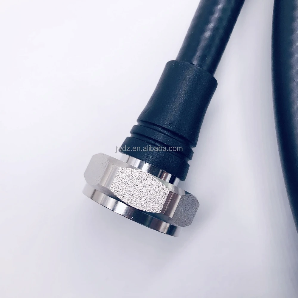
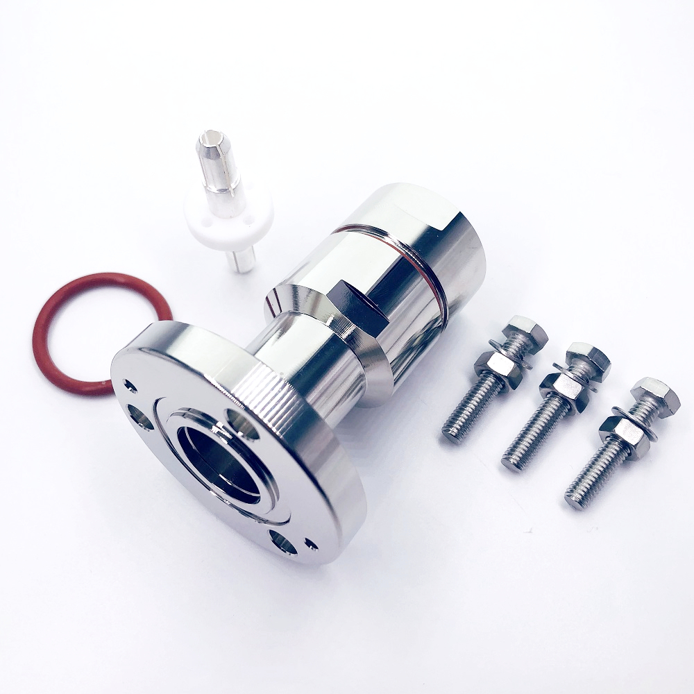
A circuit diagram describes the principle; a commercial part must also satisfy mechanical and deployment requirements. For example, a product described as a DIN 7/16 Female Low PIM 698–3800 MHz 2-Way Power Divider Power Splitter should be assessed against the actual site frequency plan, interface requirements, and system-level low-PIM criteria before it is specified.
That last point is worth stressing: product titles help identify a category, but the final selection must come from the published product specification, current test data, and the installation requirements of the RF system. In multi-stakeholder telecom procurement, engineering, purchasing, and field teams should agree on those acceptance criteria before ordering.
A Practical Selection Checklist
- Define the system impedance, frequency band, port count, and desired split ratio.
- Set limits for additional insertion loss, port matching, isolation, amplitude balance, and phase balance.
- Determine whether the device will only divide signals or may also combine them.
- Check the expected continuous, peak, and mismatch power conditions, including thermal implications for the isolation resistor.
- Verify connectors, mounting, cable routing, environmental exposure, and any low-PIM requirements.
- Review the current datasheet and qualification evidence for the exact part number and frequency range.
Quick Reference for a Wilkinson Power Splitter
Use this short review before approving a Wilkinson power splitter. A Wilkinson power splitter should match the planned frequency range. A Wilkinson power splitter should have the correct port count and connector interfaces. Check the stated insertion loss, VSWR, isolation, amplitude balance, phase balance, and power rating for the exact Wilkinson power splitter model.
For antenna distribution, a Wilkinson power splitter is evaluated as part of the whole RF path. For combining, a Wilkinson power splitter also needs a clear mismatch and thermal assessment. Do not assume every Wilkinson power splitter has the same bandwidth, balance, or isolation. Read the current datasheet for the selected Wilkinson power splitter, then verify its test conditions against the system requirement.
Conclusion
A Wilkinson power splitter is more than a device that creates two signal paths. Its quarter-wave network and isolation resistor are designed to deliver an equal split while preserving port matching and reducing output-to-output interaction. For RF passive-component selection, use the Wilkinson power splitter topology as the starting point, then validate frequency range, insertion loss, VSWR, isolation, balance, power handling, and connector compatibility against the real installation. That approach turns a familiar RF circuit into a reliable system decision.