EN
EN

What Is an RF Attenuator and When Do You Need One?
An RF attenuator is a passive component that deliberately reduces signal power by a known amount. Engineers often call a fixed resistive version an attenuator pad. Rather than trying to “fix” every strong or unstable signal with active circuitry, a correctly selected attenuator pad gives the RF chain a predictable amount of loss while preserving the impedance environment the equipment expects.
That makes it useful in communication equipment, test benches, data-center radio links, antenna systems, calibration setups, and OEM assemblies. The key is that an RF attenuator is not simply a weaker cable or a random resistor. It is specified for an attenuation value, a frequency range, an impedance, a power level, and often a connector interface.
What an RF attenuator does in a signal chain
Every RF signal path has a practical operating window. A receiver front end, mixer, amplifier, spectrum analyzer, or test port can perform poorly when the incoming level is too high. An attenuator pad introduces a controlled loss, normally stated in decibels (dB), so the signal arrives at the next stage at a more appropriate level.
For example, a 10 dB attenuator pad reduces power by a factor of ten. The exact effect on voltage depends on the system conditions, but the engineering purpose is straightforward: reduce level in a known, repeatable way. Because passive attenuators do not need a control supply, they are widely used where stable, simple level reduction is more valuable than dynamic adjustment.
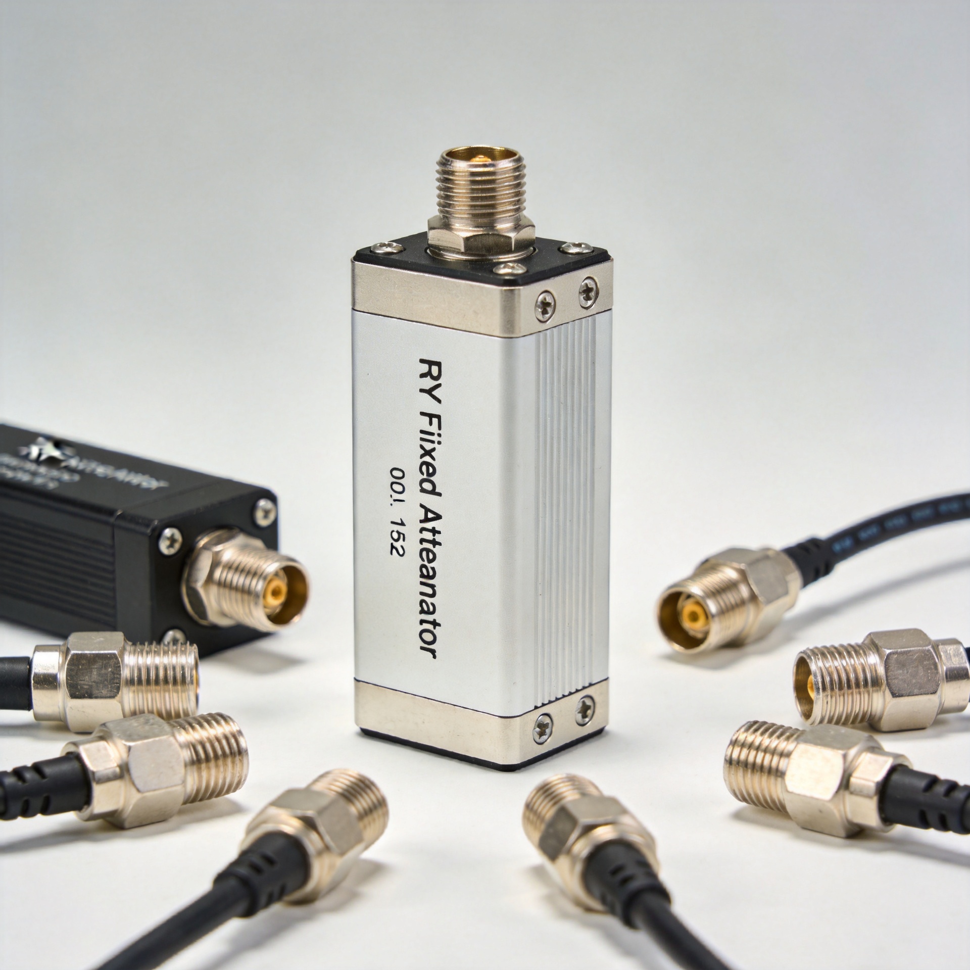
Many RF attenuators are built as resistive networks. Pi and T networks are familiar circuit forms, while packaged coaxial units place the network in a shielded mechanical format. The package and connector choice matter just as much as the resistor values once frequency, power dissipation, and reflections become significant.
When you need an attenuator pad
The most common reason to add an attenuator pad is an over-level condition. If a source is driving a sensitive input too hard, a fixed attenuator can bring the signal into the permitted range. This is common when connecting signal generators to instruments, placing a high-gain stage ahead of a receiver, or adapting modules with different nominal levels.
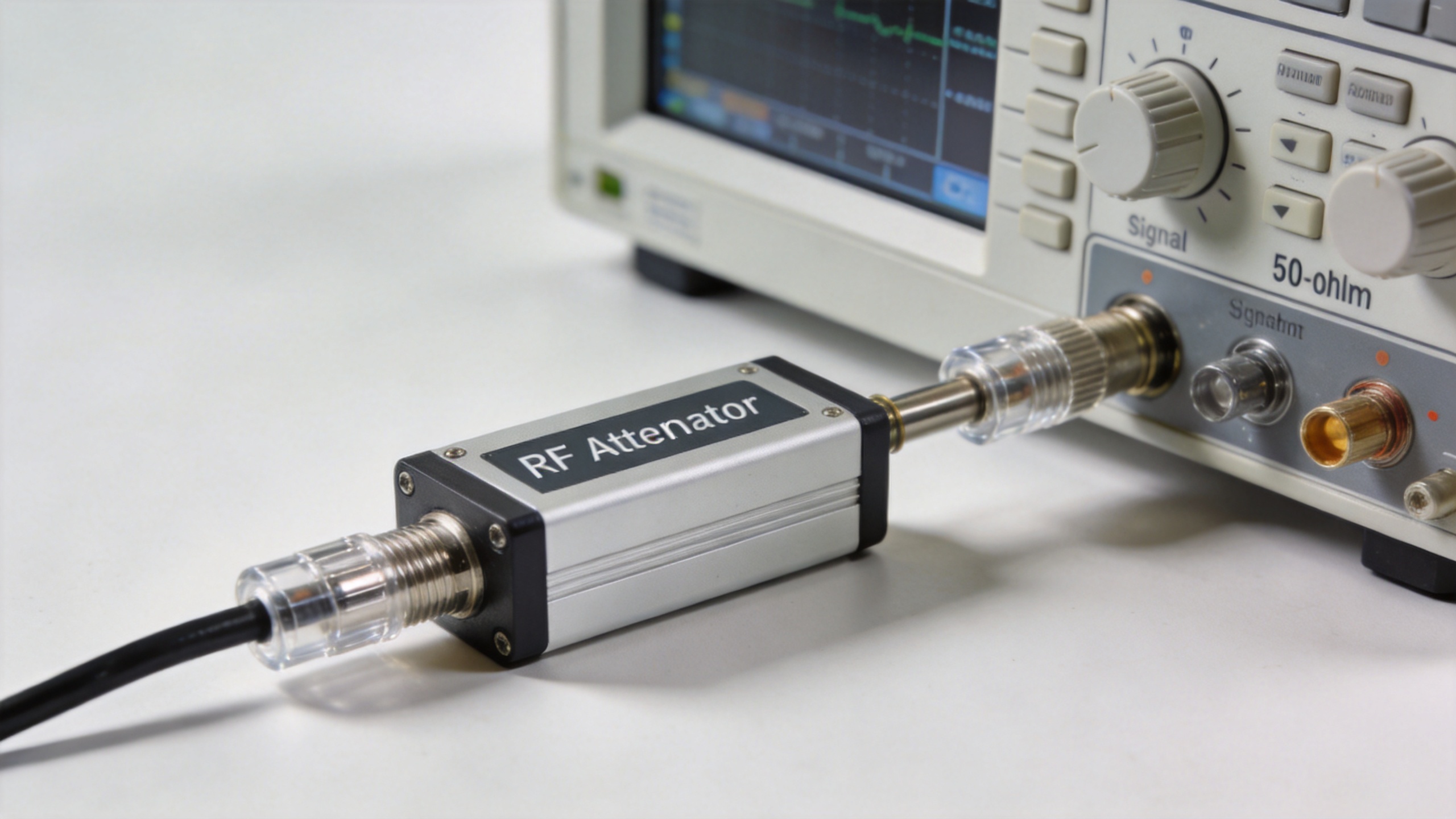
A second use is test and measurement. Engineers frequently place an RF attenuator between a source and a device under test to protect an instrument input, establish a repeatable reference level, or improve isolation while changing a setup. In this role, the known loss is part of the measurement plan, so the attenuation value must be included in the calculation.
A third use is managing mismatch effects. A well-designed attenuator pad can improve the apparent match between stages by reducing the strength of reflected energy that returns to the source. It does not replace a proper impedance match when the mismatch is severe, but it can be a practical stabilization element in a 50-ohm RF chain.
You may also use attenuation to set gain distribution across a multistage system. Instead of running every active device near its limit, designers can use fixed loss at selected points to trade a little signal level for more predictable behavior, lower overload risk, and easier troubleshooting.
Common locations for RF attenuators
- Between a signal generator and a device under test: to protect the DUT or create a known input level.
- At an instrument input: to avoid overload at a spectrum analyzer, power meter, or receiver input.
- Between active stages: to control gain distribution and reduce the impact of interactions between stages.
- Near an antenna or feed component: when the design needs a specific level adjustment and the power rating has been checked.
- In production or calibration fixtures: where repeatability matters more than a variable setting.
Placement should follow the actual system objective. Adding loss after an overloaded receiver will not solve an overload that already occurred at its input. Likewise, placing a low-power attenuator where high RF power is present can cause heating, drift, or failure.
How to select the right RF attenuator
Start with the required attenuation value. Compare the source level, cable losses, downstream gain, and allowable input level. Choose a value that leaves useful margin rather than merely meeting a conservative calculation. In many applications, a small set of fixed values such as 3 dB, 6 dB, 10 dB, 20 dB, or higher is used to build a practical adjustment toolkit.
| Selection factor | Why it matters |
|---|---|
| Attenuation value (dB) | Sets the intended reduction in the RF signal level. |
| Impedance | Must match the system, commonly 50 ohms in RF and microwave work. |
| Frequency range | Performance and return loss can change significantly outside the rated band. |
| Power rating | The component must dissipate the expected RF power with appropriate margin. |
| Connector type | Must fit the mechanical interface and support the operating frequency. |
| Accuracy and VSWR | Important when level uncertainty and reflections affect system performance. |
For a coaxial installation, confirm connector gender and interface before ordering. Also check whether the stated power rating applies across the full frequency range and under your installation conditions. A compact attenuator pad that is suitable for a low-level bench test may not be appropriate for a higher-power transmitter path.
Fixed or variable: which is better?
Choose a fixed RF attenuator when the required loss is known and stable. Fixed parts are straightforward, repeatable, and easy to document in a design or test procedure. Choose a variable attenuator when the operating level must be tuned during setup or operation. Variable solutions offer flexibility, but they add cost, control considerations, and potential performance trade-offs.
For many procurement teams and equipment builders, it is practical to keep several fixed values available for commissioning and diagnostics, then specify the final attenuator pad once measurements confirm the required loss. This reduces the temptation to solve a signal-level issue by trial and error alone.
A practical checklist before installation
- Identify whether the issue is excessive level, a measurement-protection need, gain distribution, or a mismatch-related stability problem.
- Confirm the system impedance and the complete operating frequency range.
- Calculate the likely RF power at the attenuator location, including any fault or peak condition that matters to the application.
- Choose the dB value, connector interface, and package style that fit the installation.
- Verify the final setup with appropriate measurement equipment and include the attenuator loss in the test record.
Choosing a component for an RF build
When a design needs a packaged coaxial solution, review the published attenuation value, frequency coverage, power rating, and connector configuration together. For example, this N coaxial RF attenuator option should be evaluated against the requirements of the specific signal chain rather than selected from its name alone.
An attenuator pad is a small component with a large system effect. Used in the right location and specified with the right limits, it can protect equipment, establish repeatable signal levels, and make an RF path easier to control. Used without checking impedance, frequency, and power, it can introduce a new problem instead. A sound choice begins with the signal budget, then confirms the component details.