EN
EN

1/2 Inch Feeder Cable vs Other Sizes for Base Station Runs
For a base-station RF path, selecting a microwave cable is not simply a question of choosing the largest feeder that can fit on the tower. The practical decision is a balance among attenuation, route length, band plan, mechanical loading, installation access, and the ability to service the line later. A 1/2-inch feeder is often attractive because it is easier to route than larger corrugated coax, but it is not automatically the right main-run choice for every site.
This comparison focuses on the common telecom feeder sizes—1/2 inch, 7/8 inch, and larger options such as 1-1/4 inch or 1-5/8 inch—and shows how to build a sizing decision around the actual RF loss budget. It is written for equipment makers, integrators, and procurement teams evaluating a microwave cable for base-station deployment.
Why feeder diameter matters in a base-station microwave cable run
Feeder size changes the electrical and mechanical behavior of a microwave cable. In general, a larger coaxial structure provides lower attenuation over the same distance at the same frequency. That matters most when the run is long, the operating frequency is high, or system margin is tight. A smaller diameter is usually easier to bend, lift, terminate, and route through congested pathways, but those conveniences must be weighed against the accumulated loss over the full link.
There is no universal preferred diameter for every installation. A short indoor connection, a rooftop jumper, and a long tower run have different constraints. The correct comparison begins with the permitted loss budget, then checks whether the selected cable can be installed without violating bend-radius, support, grounding, connector, or weatherproofing requirements.
1/2-inch feeder: where it fits well
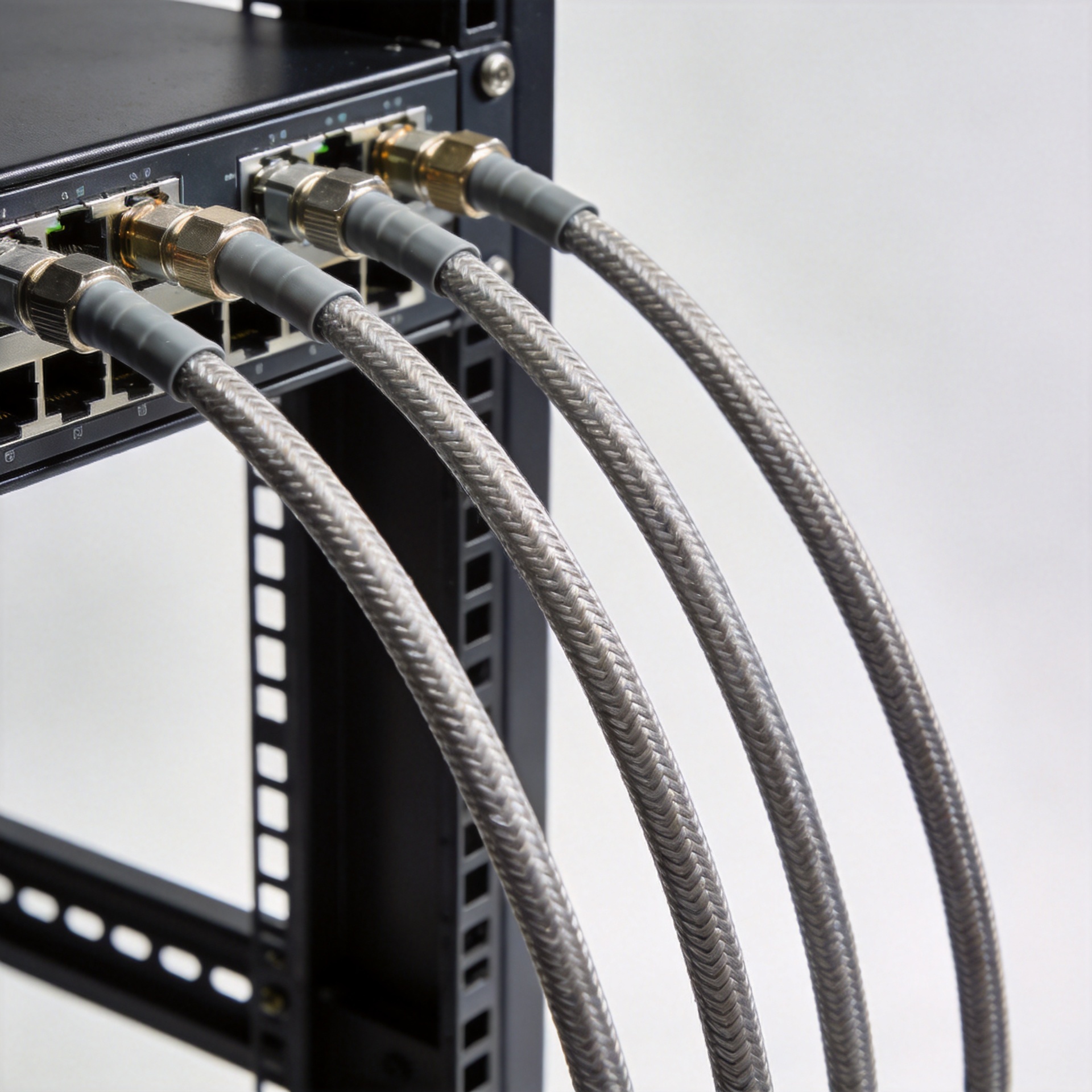
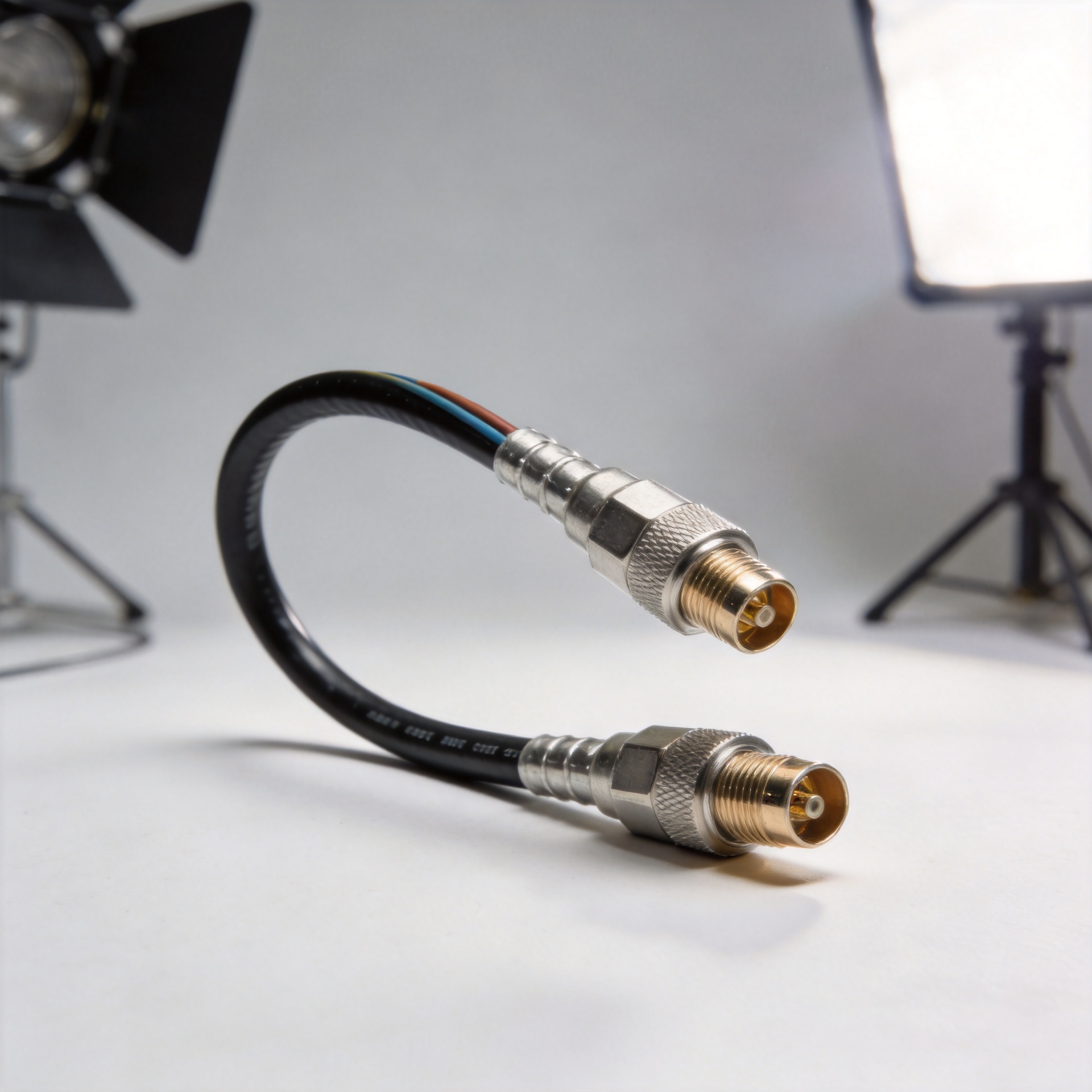
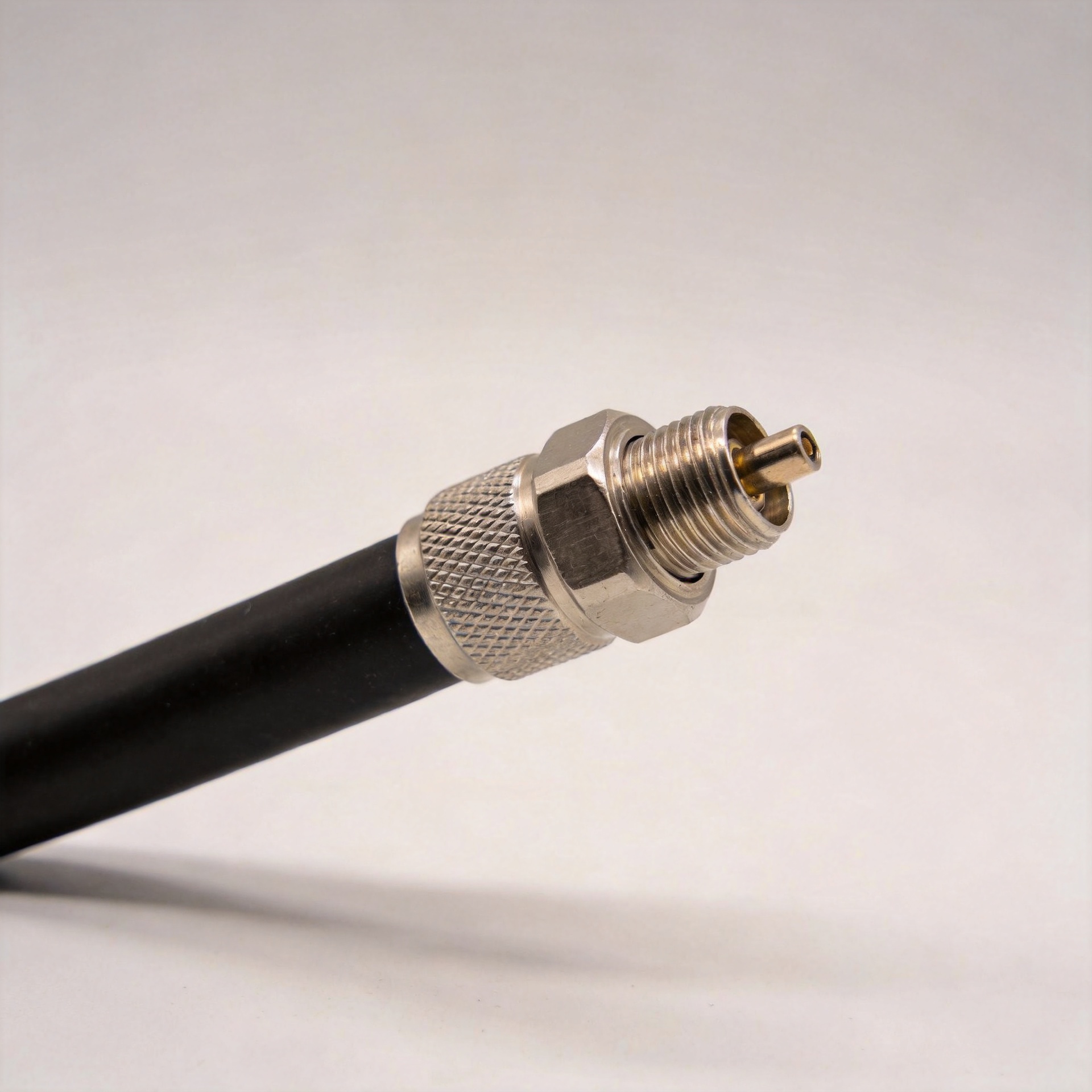
A 1/2-inch feeder is a practical microwave cable option where routing flexibility and manageable handling are important. Its smaller profile can simplify work in crowded cable ladders, equipment rooms, rooftop transitions, and retrofit projects. Installation crews can typically manage a 1/2-inch line more easily than heavier feeder sizes, particularly where pull paths include several turns or restricted access points.
The trade-off is attenuation. As frequency and route length rise, the loss of a 1/2-inch line can consume more of the system budget than a larger feeder. For that reason, it is often evaluated for short-to-medium runs, branch sections, jumpers, or sites where the RF design has adequate margin. The decision should be made from the manufacturer’s frequency-specific attenuation table for the exact cable construction, rather than from a generic diameter assumption.
For applications requiring a flexible, halogen-free jacketed option, review the actual construction and approved installation environment of the HCAAY(Z)-50-12 1/2-inch low-loss flexible cable before including it in the BOM.
7/8-inch feeder: a common choice for main runs
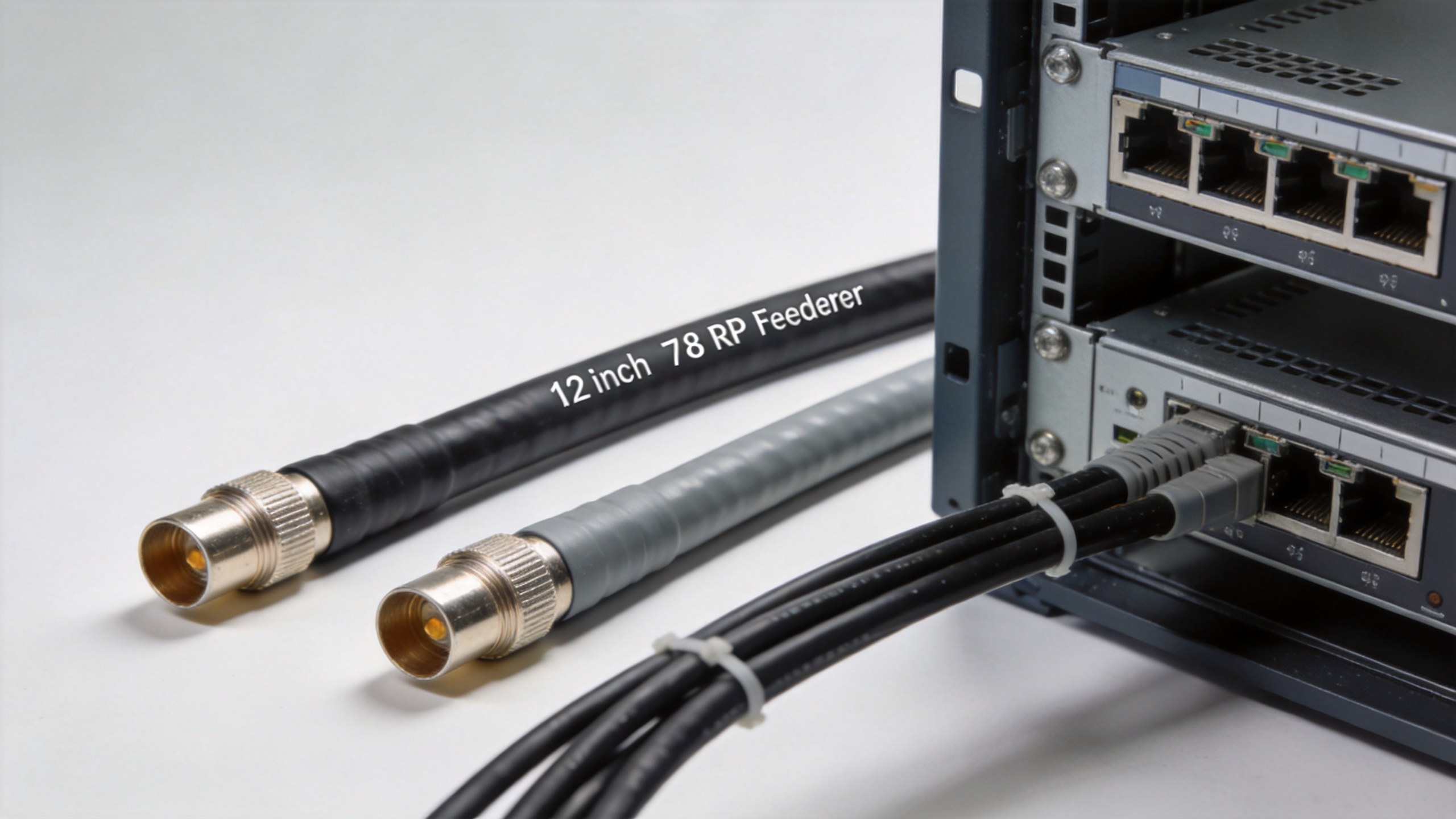
When a base station needs better transmission efficiency over a longer route, 7/8-inch feeder is often the comparison baseline. The larger diameter generally lowers loss relative to a 1/2-inch microwave cable, which can preserve more link margin across a tall tower run or a higher-frequency band. Industry references commonly describe 7/8-inch and larger cable as a main-feeder option when transmission efficiency is a major planning objective.
The mechanical cost is real. A 7/8-inch cable is heavier, less forgiving around tight corners, and more demanding to support correctly. It may increase labor, require larger clamps and entry hardware, and complicate routing in an existing site. A project team should calculate whether the saved RF loss is worth the added installation effort and hardware cost instead of treating 7/8 inch as a default upgrade.
Larger feeder sizes: when lower loss outweighs installation complexity
Sizes above 7/8 inch are normally considered when a microwave cable run is long, power handling is demanding, several bands share a constrained margin, or the operator wants to minimize feeder contribution to total path loss. These larger cables can be suitable for major outdoor routes and high-capacity sites, but they introduce more weight, larger bend radii, and more substantial mounting requirements.
They are usually less attractive for short equipment interconnects or retrofit pathways with limited clearance. The design team should also verify compatible connectors, grounding kits, weatherproofing parts, and available installation tooling before committing to a larger size. Electrical performance improves only if the complete RF path is installed and terminated correctly.
Side-by-side comparison for base-station planning
| Feeder size | Typical planning advantage | Typical trade-off | Often considered for |
|---|---|---|---|
| 1/2 inch | More manageable routing and handling | Higher loss than larger feeder over the same route | Short-to-medium runs, constrained pathways, flexible sections |
| 7/8 inch | Lower-loss balance for many main feeder designs | More weight and a larger routing envelope | Longer tower or rooftop main runs |
| 1-1/4 inch and larger | Lowest feeder-loss potential in the comparison | Highest mechanical and installation complexity | Long, high-demand, or margin-sensitive outdoor routes |
The table is a planning guide, not a substitute for an RF calculation. Actual microwave cable attenuation depends on frequency, construction, conductor design, dielectric, temperature, connectors, and the specific installation. Compare the published attenuation values at the bands you will operate, then add connector and jumper losses to the total budget.
A practical selection workflow
- Define the RF budget. Set the maximum acceptable feeder loss at each operating frequency and include reasonable installation allowances.
- Measure the real route. Use the installed path length, not the straight-line drawing distance. Include risers, service loops, transitions, and future routing constraints.
- Compare exact cable data. Evaluate the manufacturer’s attenuation and power-handling documentation for the candidate microwave cable types.
- Check mechanical conditions. Confirm bend radius, hanger spacing, wind exposure, entry sealing, grounding, and pull access.
- Validate the whole interconnect. Connector families, jumpers, grounding kits, and workmanship can affect the final result as much as diameter selection.
Microwave cable checks before placing the purchase order
Before purchasing a microwave cable, ask the supplier for the attenuation table at every planned operating band, the approved connector options, and the installation limits for the exact part number. This protects the design from a common mismatch: comparing a 1/2-inch microwave cable to a 7/8-inch feeder using values taken from different constructions or frequencies.
For a 1/2-inch microwave cable, document the run length, maximum operating frequency, route bends, service-loop allowance, and expected connection count. For a larger microwave cable, add the lifting plan, hanger schedule, entry hardware, and space needed to maintain bend radius. These details make the electrical comparison useful to the installation team as well as the RF designer.
Procurement teams sourcing through rf coaxial cable manufacturers should request controlled data sheets and confirm that cable, connectors, grounding components, and weatherproofing accessories are specified as a compatible system. A microwave cable that looks suitable on a catalog page may still be unsuitable if the actual route, termination method, or environmental jacket requirement is different.
How to avoid common sizing mistakes
One common mistake is selecting 1/2-inch feeder solely because it is easier to install, then discovering that the calculated loss leaves too little margin at the upper operating band. The opposite mistake is specifying the largest cable for every section, even where a short route or indoor transition gains little electrical benefit but creates a difficult installation.
Another issue is comparing cables by diameter alone. A microwave cable must be assessed as a complete, documented assembly: cable construction, frequency range, jacket suitability, connectorization, installation practice, and environmental exposure all matter. Keep the electrical and construction data tied to the exact part number in the project record.
Choosing the right feeder size
Use 1/2-inch feeder when the loss budget supports it and installation flexibility is valuable. Move toward 7/8 inch when the main-run length, frequency, or required margin makes lower attenuation more important. Evaluate larger sizes when the route is long or the RF design is especially loss-sensitive. For every option, verify the published data for the exact microwave cable and model the complete installed path before procurement.
A disciplined comparison gives procurement teams a clearer specification, helps installers plan the route and hardware, and reduces the chance that a seemingly convenient cable choice becomes a performance constraint after commissioning.