EN

5G Directional vs. Omni Antennas: Which One Fits Your Deployment?
Choosing a 5g directional antenna is not simply a matter of selecting the highest gain on a data sheet. In a DAS or indoor-coverage project, the antenna pattern must fit the building geometry, signal-source location, frequency plan, cable routing, and commissioning targets. A directional antenna concentrates energy toward a planned service area; an omnidirectional antenna distributes energy around its mounting point. Both can be correct choices in the same project.
For system integrators and procurement teams, the practical question is: where should RF energy go, and where should it not go? Start there, then confirm electrical performance, mechanical installation conditions, and the link budget.
Directional and Omnidirectional Patterns: The Core Difference
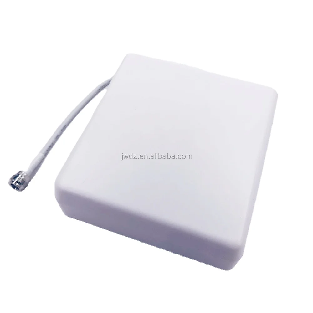
A 5g directional antenna focuses its main lobe in a defined direction. Panel and wall-mount antennas are common examples. By concentrating the pattern, a directional design can improve coverage toward a corridor, seating block, platform, façade, or edge zone. The trade-off is that coverage behind and beside the antenna is reduced.
An omnidirectional antenna radiates around its axis, commonly approximating 360 degrees in the horizontal plane. Ceiling-mount omni antennas are often useful when a space is relatively open and users move in several directions from the antenna location. Their benefit is simpler, broad-area distribution; their limitation is less control over where the RF energy is placed.
As antenna gain increases, the usable coverage pattern generally becomes narrower in at least one plane. That is why gain should be read together with horizontal and vertical beamwidth, not as an isolated “more is better” number.
5G Directional Antenna vs. Omni Antenna: A Deployment Comparison
| Selection factor | 5g directional antenna | Omnidirectional antenna |
|---|---|---|
| Coverage pattern | Focused toward a planned sector or path | Broad coverage around the mounting point |
| Suitable geometry | Corridors, long halls, perimeter zones, targeted rooms, outdoor-to-indoor edges | Open offices, lobbies, retail floors, central indoor areas |
| Interference control | More control over spillover beyond the target area | Less pattern control where adjacent zones must be isolated |
| Mounting approach | Typically wall, panel, or aimed ceiling placement | Typically ceiling placement near the center of a coverage cell |
| Design risk | Coverage gaps if aiming or overlap is wrong | Overspill or weak edge performance in long or irregular spaces |
When a 5G Directional Antenna Is the Better Choice
Select a 5g directional antenna when the coverage objective is narrow, asymmetric, or deliberately contained. Typical examples include a long corridor, a warehouse aisle, a tunnel approach, a stadium seating section, a platform, or a room that needs service without unnecessarily energizing adjacent areas.
- Long, linear spaces: Aim the main lobe along the travel path rather than placing an omni antenna at one end and expecting uniform distance performance.
- Edge and perimeter coverage: Use a panel pattern to send energy inward from a wall or to address a boundary zone.
- Signal containment: A focused pattern can help reduce coverage spill into neighboring floors, tenants, or low-priority areas when combined with the right power settings.
- Known user concentration: Target a queue, work cell, seating bank, or equipment area where demand is concentrated.
For a directional run, the installation team should document azimuth, downtilt if applicable, mounting height, cable length, and the intended handoff overlap. A small aiming change can alter edge coverage more than a small gain difference between products.
When an Omni Antenna Is the Better Choice
Use an omni antenna when users and devices are distributed around the antenna and the space is open enough for a broadly symmetric cell. In many indoor DAS designs, ceiling omni antennas are a sensible starting point for lobbies, open-plan offices, retail areas, and general circulation zones.
However, an omni pattern does not eliminate planning work. Ceiling height, obstructions, reflective materials, room partitions, and neighboring cells still influence the final result. In a multi-floor property, vertical leakage and inter-floor interaction should be checked during walk testing rather than assumed from the floor plan.
A 5g directional antenna remains useful even in a mostly omni layout. For example, an open lobby may use a central ceiling omni antenna while a 5g directional antenna serves a side corridor or a glass-fronted perimeter. The pattern choice should follow the service-zone shape, not a rule that one antenna family must cover an entire floor.
Where an omni cell produces weak edges because walls, elevators, or dense shelving interrupt the path, a correctly aimed 5g directional antenna can cover the affected zone without relocating every ceiling device. Conversely, do not replace a central omni with a 5g directional antenna merely to obtain a higher gain value; the new pattern may leave users behind the panel with inadequate coverage.
Use the Floor Plan Before You Use the Gain Number
A reliable antenna decision begins with the coverage map. Mark the intended service areas, low-priority areas, wall materials, corridors, risers, equipment rooms, and likely user-density zones. Then ask four questions:
- Does the target area spread around a central point or extend primarily in one direction?
- Do adjacent areas need lower signal levels or cleaner cell boundaries?
- Where can installers place the antenna without creating cable-loss or access problems?
- Does the selected antenna cover the required 5G and legacy bands in the project band plan?
If the answer to the first two questions is “one direction” and “yes,” a 5g directional antenna deserves close consideration. If the space is open and centrally served, an omni model may reduce the number of aimed devices and simplify the layout.
Do Not Ignore the RF Chain Around the Antenna
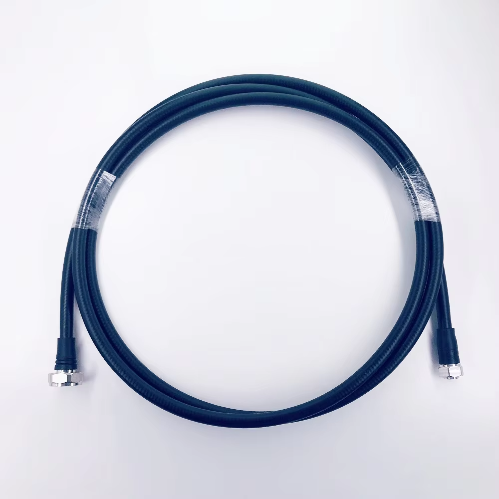
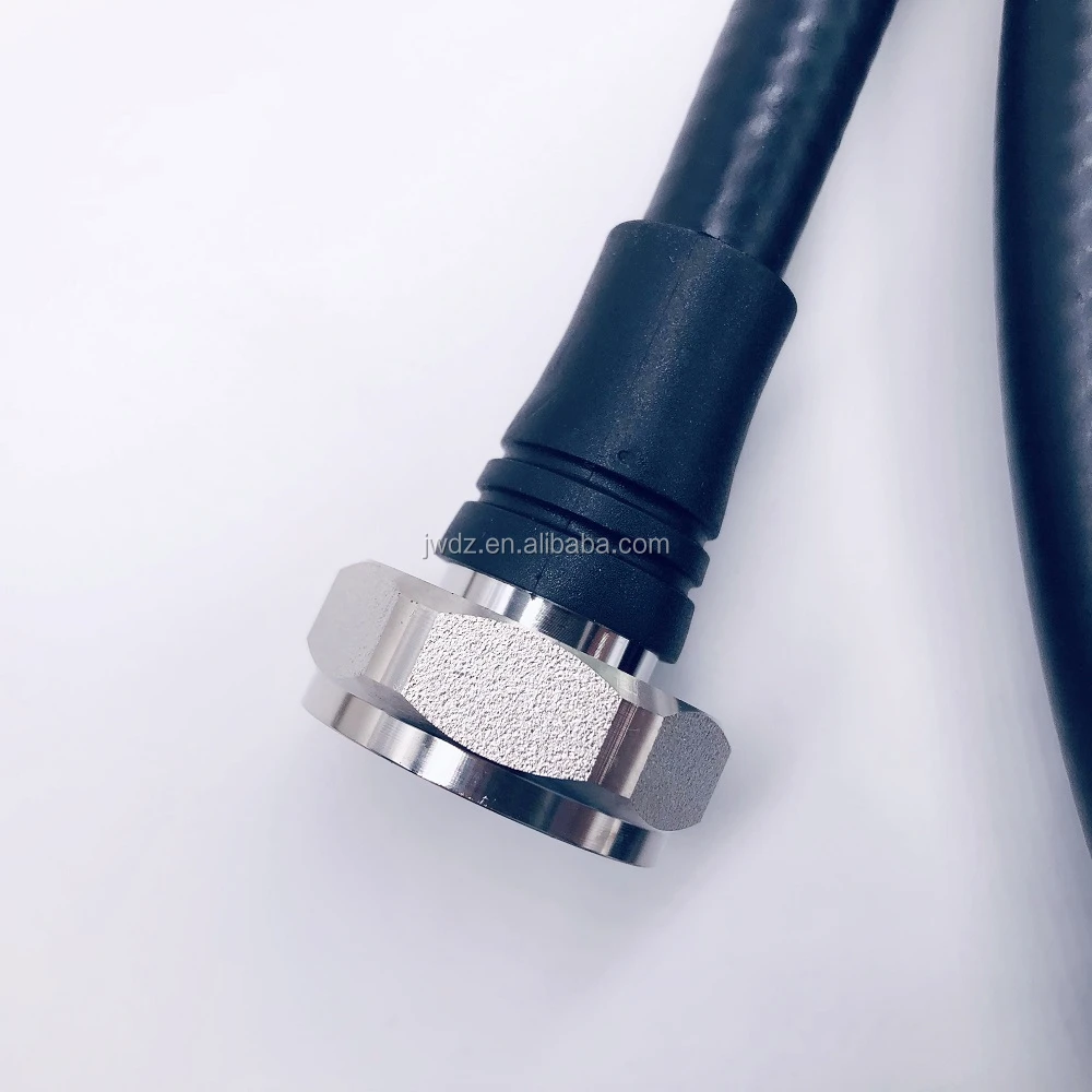
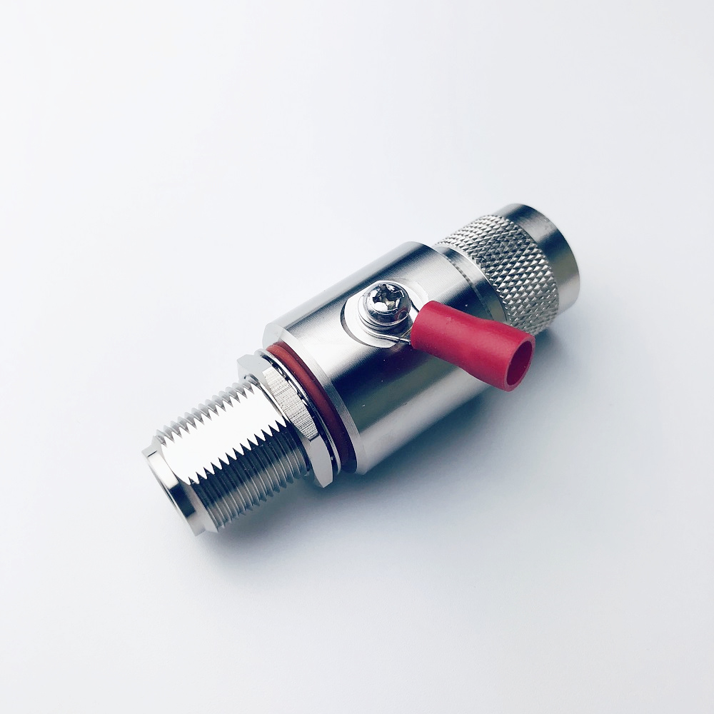
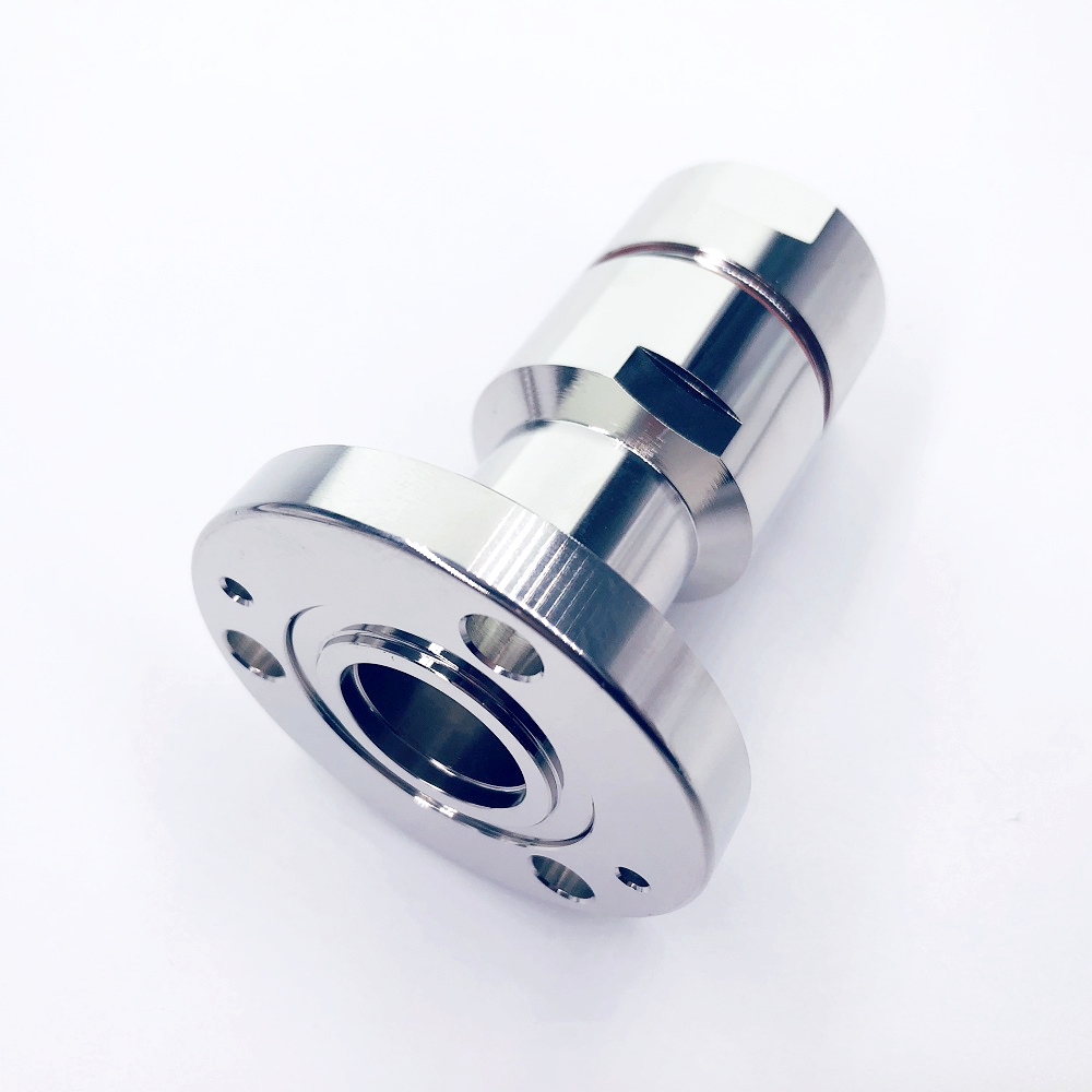
An antenna pattern cannot compensate for losses or defects elsewhere in the DAS. Confirm the full RF path: feeder and jumper loss at the operating bands, connector interfaces, passive-device specifications, return loss, PIM requirements, grounding, and weather protection where applicable. For multi-band 5G projects, verify the entire operating range rather than assuming a label such as “5G” guarantees suitability for every band.
For targeted outdoor or IBS/DAS applications, a 5G 698–3800 MHz high-gain outdoor panel directional antenna for IBS DAS can be evaluated as part of the RF path, provided its published specifications match the project frequency, mounting, and coverage requirements. Product selection should still be validated with the project link budget and site survey.
A Practical Selection and Commissioning Checklist
- Match the antenna pattern to the floor-plan geometry and intended user locations.
- Review gain together with horizontal and vertical beamwidth.
- Verify frequency coverage, impedance, connector type, PIM target, and power handling against the actual design.
- Plan mounting height, orientation, cable routes, bend radius, grounding, and weatherproofing before ordering.
- Use predictive modeling as a starting point, then validate with field measurements, walk tests, and acceptance criteria.
- Record final antenna positions and orientations for maintenance and future expansion.
Final Decision: Choose the Pattern That Controls the Coverage You Need
The right choice is often not directional or omnidirectional across the whole building. A well-designed 5G DAS may use ceiling omnis in open zones and directional panels for corridors, perimeter areas, or coverage cells that need tighter control. Choose a 5g directional antenna when you need focused reach and controlled spillover. Choose an omni antenna when broad, balanced coverage around a central mounting point is the priority.
Before final procurement, review the floor plan, band plan, link budget, installation constraints, and test plan together. That process turns antenna selection from a catalog comparison into a deployment decision that can be verified at commissioning.