EN

Leaky Feeder Cable Installation Planning for Mine Communication
Reliable underground radio coverage begins long before a cable is pulled. In a mine, a leaky feeder installation is a route, access, safety, and maintenance decision as much as it is an RF decision. Leaky feeder systems are used in tunnels and mines because normal radio propagation is limited in confined underground spaces. The practical objective is to create a planned signal path that reaches the working areas where people need two-way communication while remaining inspectable as headings advance and conditions change.
From an installation perspective, the key question is not simply “Where can the cable fit?” It is “Where can this cable provide the intended coverage, survive the operating environment, and still be safely reached for inspection or repair?” This article sets out a decision-stage framework for leaky feeder installation planning. It should be used alongside the system design, mine safety rules, cable manufacturer instructions, and approvals for the specific site.
1. Start the Leaky Feeder Installation Plan With a Coverage-and-Route Survey
Map communication demand before marking supports. Include portals, main declines, shafts, intersections, loading areas, refuge locations, workshops, pump stations, and any planned development headings. Mark operational zones that will move over time, because those areas may require extension sections or a different maintenance strategy.
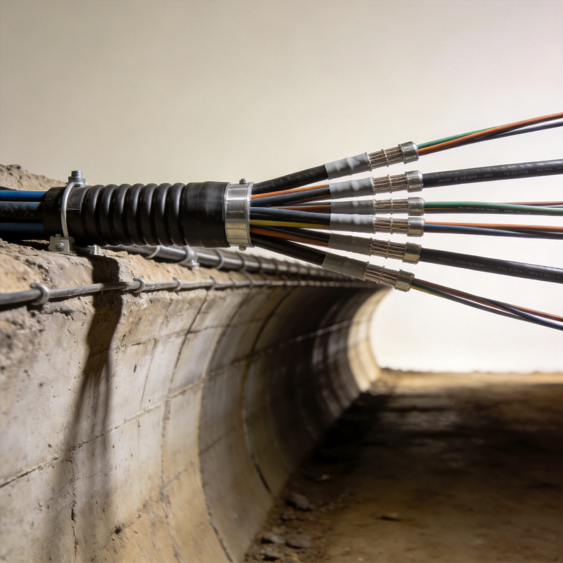
A leaky feeder cable installation plan should then compare the desired radio coverage path with the physical route. Look for locations that avoid likely impact, allow safe cable pulling, and preserve access to couplers, splitters, amplifiers, terminations, and test points. In my experience, a route that looks shorter on a drawing can be more expensive over the system life if it crosses a high-damage area or leaves no practical way to isolate a future fault.
- Record chainage or other mine-reference points for every major component location.
- Identify the power, signal, drainage, ventilation, and vehicle-clearance interfaces before installation begins.
- Plan separate access points for routine inspection and urgent repair.
- Confirm how the route will be extended when working faces move.
2. Check the Environment Before Selecting Supports and Handling Methods
Mine conditions change the real-world demands on a leaky feeder installation. Water, humidity, dust, vibration, blasting activity, mobile equipment, roof movement, and restricted clearances can all affect the route and support strategy. If the cable passes through areas with changing ground conditions or frequent vehicle movement, give mechanical protection and accessible re-routing options more weight than a neat initial layout.
Here is a question worth asking before the route is finalized: can the crew inspect and replace a damaged section without interrupting unrelated mine activity? If the answer is no, reconsider the route, component spacing, or sectioning plan. The installation detail that procurement specifications often overlook is not the cable alone, but the combination of support method, bend control, splice accessibility, labeling, and safe work access.
Use the manufacturer’s minimum bend-radius and pulling guidance for the chosen cable. Avoid uncontrolled dragging, sharp turns, crushing points, and unsupported spans. A tunnel-radio installation guide also advises controlled unreeling with suitable reel equipment rather than rolling cable on the mine floor; that is a useful handling principle, but the selected cable’s own instructions remain the governing reference.
3. Define Physical Separation, Fixing, and Sectioning Rules
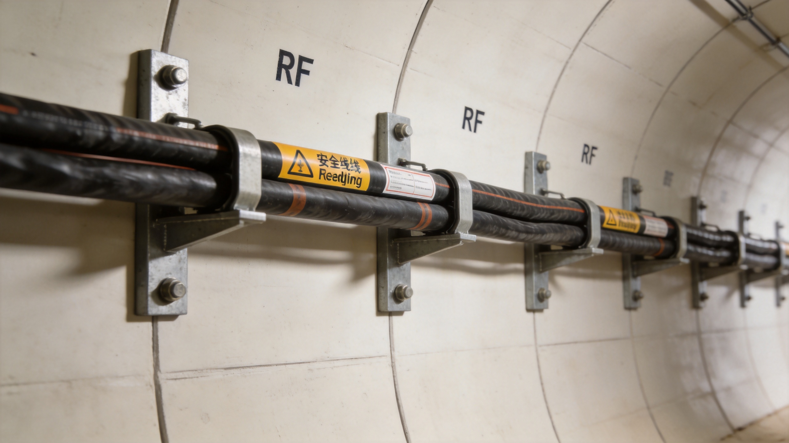
The next step in leaky feeder cable installation planning is to turn the route into installation rules the crew can follow consistently. Document the approved support type, support spacing, clearances from other services, transition details at corners, and protections at crossings. Do not rely on a generic spacing figure from another project: support requirements depend on the cable construction, site conditions, local rules, and equipment hazards.
Separation deserves careful attention. Parallel high-power services, potential interference sources, water paths, and mechanical hazards all need review by the site engineering and safety teams. Keep joints and active components where technicians can identify them and work on them safely. Each section should have a clear start and end reference so a future technician does not have to trace an entire tunnel run to locate a suspected loss or damaged splice.
| Planning item | What to confirm before pulling | Why it matters |
|---|---|---|
| Route reference | Chainage, branch point, and component map | Speeds fault isolation and extension planning |
| Supports | Approved fixing type and cable-specific spacing | Reduces sagging, abrasion, and impact exposure |
| Crossings | Vehicle, drainage, and service-interface protection | Controls predictable mechanical damage |
| Sectioning | Accessible joints, terminations, and test points | Improves maintenance and commissioning traceability |
4. Plan Cable Pulling, Identification, and Quality Checks as One Workflow
A successful leaky feeder installation needs a pull plan, not just a work order. Confirm delivery and storage locations, reel orientation, approved pulling equipment, communications between crew members, and stop points for visual checks. If a route includes confined turns or elevation changes, document how the crew will control tension and prevent damage. Do not treat a cable that looks undamaged as proof of performance after an uncontrolled pull; inspection and system testing are both needed.
Label sections and installed components as the work progresses. Photographs, route references, cable identifiers, splice records, and test results should become part of the handover package. This is especially important for a mine network, where the route may later be extended or temporarily altered as production advances.
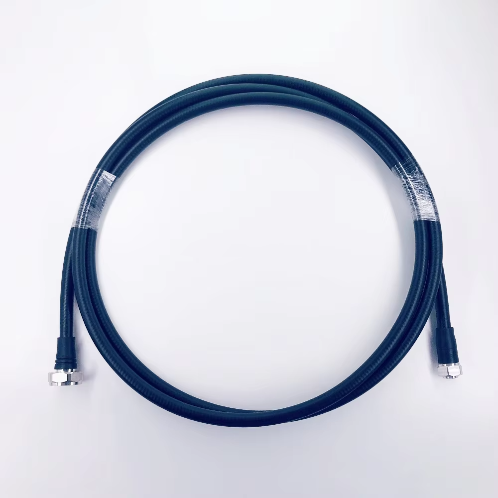
For projects requiring a confirmed product source, the verified product record for this plan is High Quality 75 Ohm 75-10 Slywv Leaky Feeder Cable for Tunnel, Mine Communication. Final cable selection must still be checked against the project frequency plan, coverage design, environmental demands, and approved installation documentation.
5. Build Inspection and Maintenance Access Into the Original Design
Regular inspection is easier when the initial leaky feeder installation identifies what to inspect and where. Define periodic checks for visible jacket damage, loose supports, water exposure, unauthorized changes near the route, component labels, and any sections vulnerable to mobile equipment or ground movement. Maintenance teams also need a consistent record of repairs. Poor splicing practice and rough handling can turn a small local problem into a recurring communications issue, so record the repair method and retest the affected section before closing the job.
It is tempting to treat commissioning as the finish line. It is not, quite. Commissioning confirms the installed condition; the maintenance plan determines whether that condition can be sustained. For expanding mine operations, include a review trigger whenever a route is extended, services are relocated, or operating conditions change.
Leaky Feeder Installation Handover Checklist
- Coverage zones and route references have been approved by operations, engineering, and safety stakeholders.
- The cable type, handling limits, bend requirements, and support method match the approved project documentation.
- Crossings, environmental hazards, and access restrictions are documented with mitigation measures.
- Components, joints, and test points are labeled and recorded on an as-built route map.
- Commissioning results, inspection intervals, and repair procedures are included in the maintenance handover.
A disciplined leaky feeder installation plan reduces avoidable rework and makes underground communication infrastructure easier to manage as the mine changes. Prioritize coverage intent, safe routing, controlled handling, accessible sectioning, and traceable maintenance records—not just the fastest path for the first cable pull.