EN
EN

BNC Male Connector Specifications: 50Ω vs. 75Ω, Crimp vs. Solder, and Cable Compatibility
If you've specified a BNC male connector by impedance alone and assumed the cable series would sort itself out, you're not alone—and you're in good company for the kind of mistake that only reveals itself at commissioning. The connector you pull from stock may meet every electrical parameter on paper while still being the wrong choice for your cable OD, installation tooling, or system frequency range. This guide works through the three decisions that actually separate a correct BNC connector specification from one that just looks correct: impedance class, termination method, and cable compatibility.
50Ω vs. 75Ω: Which Impedance Class Do You Actually Need?
Think of connector impedance like pipe diameter in a pressurized flow system: an abrupt change in diameter doesn't stop the flow, but it creates turbulence, which translates to signal reflections in RF terms. The 50Ω and 75Ω BNC male connectors are mechanically interchangeable to the extent that they can physically mate, but their internal geometries differ. A 50Ω center pin is dimensioned to maintain 50Ω impedance continuity; a 75Ω center pin is slightly smaller to achieve the same result at 75Ω. Forcing a 50Ω male into a 75Ω female can deform the female contact, making every subsequent 75Ω mating unreliable.
The electrical consequences of mismatching depend heavily on frequency. At signals below 10MHz, the impedance mismatch introduces negligible reflected energy—for many low-frequency instrumentation or baseband video applications, the two types are functionally interchangeable. Above that threshold, the VSWR penalty accumulates. A standard 50Ω BNC male connector is specified for DC to 4GHz with a VSWR maximum of 1.3 (−18 dB return loss). The 75Ω equivalent carries a VSWR maximum of 1.5 (−14 dB) across the same standard range, with extended-range designs reaching DC to 12GHz at tighter tolerances for broadcast 12G-SDI infrastructure. Both variants share a voltage rating of 500V RMS and an insertion loss specification of 0.2 dB maximum at 3GHz.
| Specification | 50Ω BNC Male | 75Ω BNC Male |
|---|---|---|
| Impedance | 50Ω | 75Ω |
| Frequency range (standard) | DC – 4 GHz | DC – 4 GHz |
| Frequency range (extended) | DC – 12 GHz | DC – 12 GHz |
| VSWR maximum | 1.3 (−18 dB) | 1.5 (−14 dB) |
| Voltage rating | 500V RMS | 500V RMS |
| Insertion loss @ 3GHz | 0.2 dB max | 0.2 dB max |
| Mating cycles | ≥500 | ≥500 |
| Interface standard | MIL-STD-348, IEC 61169-8 | MIL-STD-348 |
| Typical application | RF test, instrumentation, antenna feeds, LMR cable assemblies | CCTV, composite video, HD-SDI/12G-SDI broadcast |
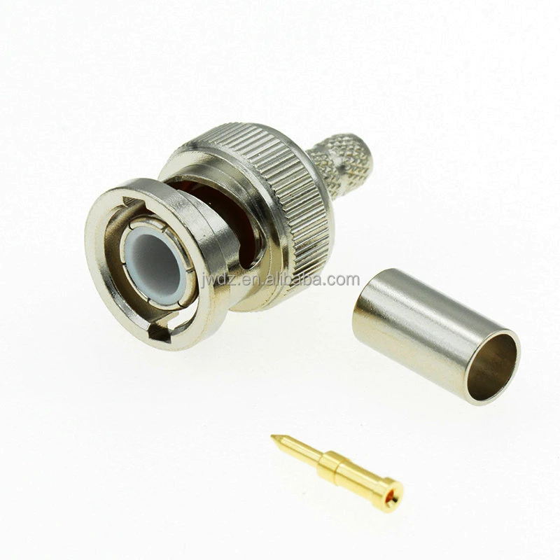
If your system operates at RF frequencies—antenna feeds, test instrumentation, two-way radio base stations, or cellular distributed antenna systems, specify 50Ω. If you're working on video infrastructure, particularly analog CCTV, HD-SDI, or 12G broadcast video over RG59 or equivalent 75Ω cable, specify 75Ω. A BNC connector for CCTV infrastructure almost universally calls for 75Ω; selecting 50Ω introduces a reflection that, while subtle at short cable runs, compounds over longer distances or higher video bandwidths.
Termination Method: Crimp, Clamp, or Solder?
Here's a question worth sitting with before you finalize your BNC plug specification: how many of these assemblies will be terminated in the field by technicians working without a bench vise? The answer should inform your termination method choice as much as the RF performance data does.
Crimp termination achieves the most consistent center-conductor and ferrule contact geometry of the three methods. A properly crimped joint creates a cold-weld between the ferrule and cable braid that resists vibration-induced loosening, and the cycle time per assembly is predictable. The limitation is tooling dependency: correct crimp dies must be matched to both connector and cable series. An LMR195 crimp die specification is not interchangeable with an LMR400 die, and using incorrect dies produces joints that appear mechanically sound but fail impedance and insertion loss checks. For production environments assembling high volumes of identical cable types, crimp is the preferred method.
Clamp (compression) termination does not require matched crimping dies—a single compression tool handles a range of connector sizes. This makes it the preferred choice for field assembly where technicians may encounter mixed cable types across a day's work. The trade-off is mechanical: clamp joints rely on compressive force rather than a cold-weld, and over repeated thermal cycles or vibration exposure, clamping force can relax. For fixed-installation infrastructure with infrequent mating cycles, this is generally acceptable.
Solder termination offers the lowest tooling cost but the highest variability. Solder joint quality depends heavily on technique, flux management, and heat control. Excess heat at the cable dielectric affects impedance at the termination point; insufficient heat produces a high-resistance joint that degrades with time. If your assembly environment cannot maintain consistent soldering discipline, the electrical performance advantage of solder disappears—and the field-replaceability of a solder joint is worse than either alternative.
| Factor | Crimp | Clamp | Solder |
|---|---|---|---|
| RF consistency | High | Medium-high | Variable |
| Tooling requirement | Cable-specific dies | Universal compression tool | Soldering iron, flux |
| Field suitability | Medium | High | Low–medium |
| Vibration resistance | Excellent | Good | Variable |
| Replaceability | New connector required | Reusable (some types) | Reworkable |
| Production throughput | Fast, consistent | Fast | Slower |
Cable Compatibility: Matching Your BNC Male Connector to the Right Cable Series
A common field issue arises when a connector batch meets every written specification but won't crimp correctly—typically a cable OD mismatch. BNC male connectors are dimensioned to specific cable outer diameters; the center-contact bore, ferrule inner diameter, and body bore are all sized to the cable's dielectric and jacket dimensions. Using a connector specified for RG58 on LMR195 will produce a joint that appears assembled but has incorrect contact depth and ferrule compression—an error the finished assembly's visual inspection cannot catch.
The following table maps the most common coaxial cable series to their compatible BNC male connector configurations. Cable OD values are approximate; confirm against the actual cable datasheet before finalizing connector stock orders.
| Cable Series | Nominal OD | Impedance | Recommended BNC Male Connector |
|---|---|---|---|
| RG58, LMR195, 3D-FB | ~5.0 mm (0.195 in) | 50Ω | BNC Male Crimp for LMR195/3D-FB/RG58 |
| LMR300, 5D-FB | ~7.6 mm (0.300 in) | 50Ω | BNC Male Clamp for LMR300/5D-FB |
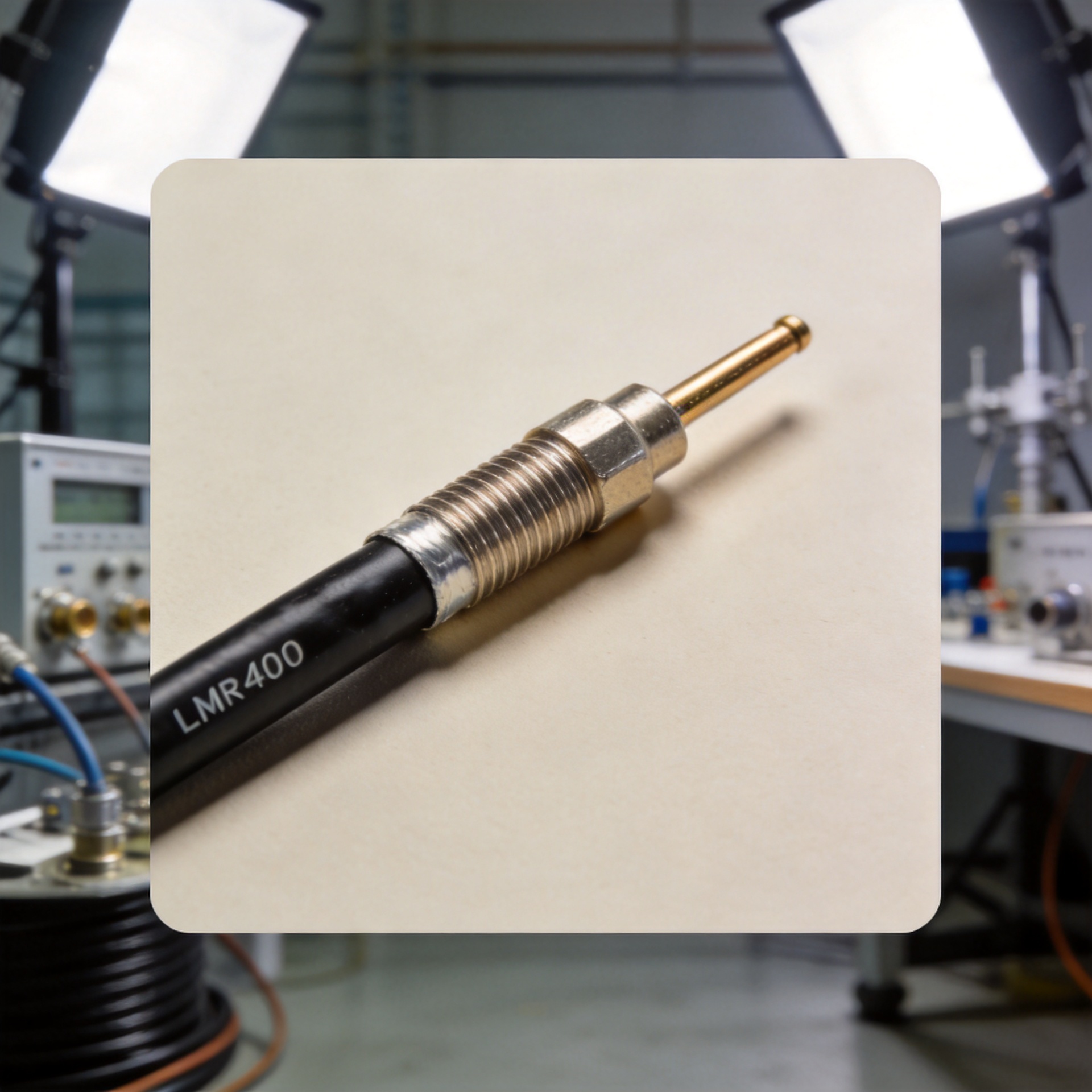
| LMR400, CNT400, RG213, RG214, RG8/U | ~10.3 mm (0.405 in) | 50Ω | BNC Male for LMR400/CNT400/RG213/RG214/RG8/U |
| RG59, RG6 | ~6.1–6.9 mm | 75Ω | 75Ω BNC male crimp (CCTV/video infrastructure) |
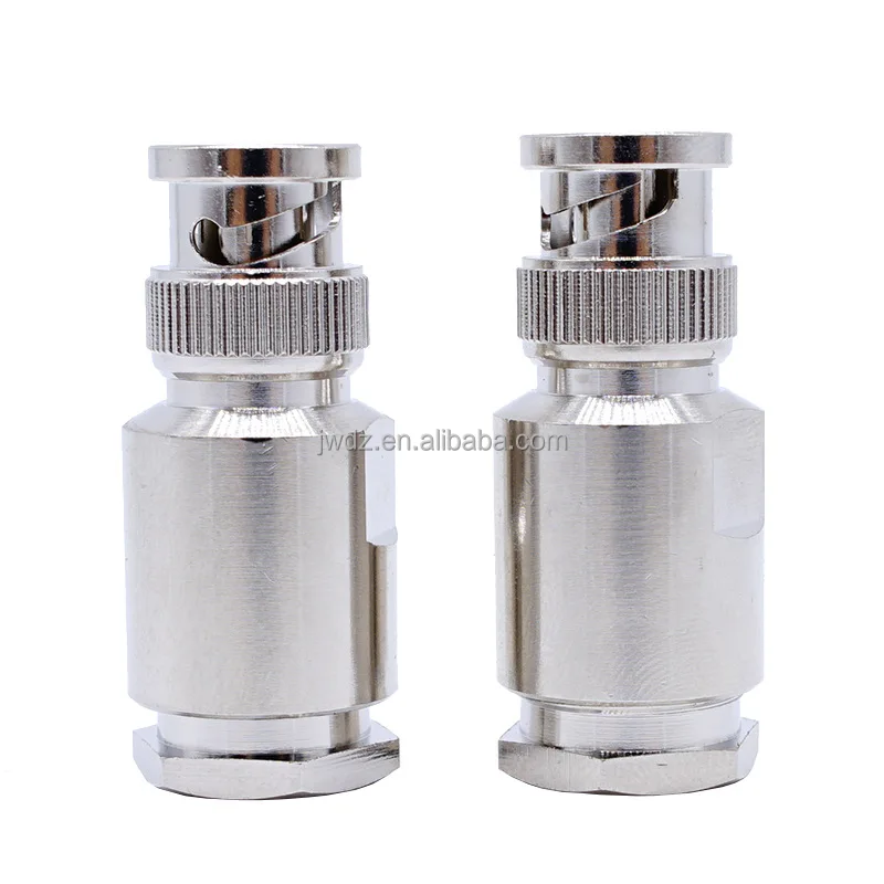
For projects involving distributed antenna systems (DAS), broadcast antenna distribution, or cellular base station feeder infrastructure, LMR400-series cable is common for trunk runs, with LMR195 or RG58 used for shorter jumper assemblies at equipment interfaces. Each cable transition requires the correctly matched connector bore; a single out-of-spec termination in a long link introduces a VSWR anomaly that can be difficult to isolate during commissioning without swept-frequency testing from end to end.
BNC Male Connector Selection: A Quick Decision Checklist
Before placing your connector order, confirm these four parameters against your project bill of materials:
- Impedance class: 50Ω for RF/antenna/instrumentation; 75Ω for CCTV/video/broadcast
- Cable series and exact OD: Match connector bore dimensions to the actual cable outer diameter, not the assumed cable series equivalence
- Termination method: Crimp for high-volume bench assembly with matched dies; clamp for mixed-cable field work; solder only where assembly quality can be consistently maintained
- Frequency requirement: Standard BNC specified to 4GHz; confirm extended-range designs if operating above 4GHz in 12G broadcast or precision RF measurement environments
Zhenjiang Jiewei has manufactured RF connectors and coaxial cable assemblies for over 25 years, serving telecom, broadcast, and infrastructure integrators across global markets. Their BNC male connector range covers the LMR and RG cable series most frequently specified in digital antenna and CCTV projects—crimp and clamp termination styles available for the most common cable diameters. Direct factory engineering support is available for connector-to-cable compatibility and installation method questions specific to your project requirements.