EN

How to Evaluate Custom Coax Cable Assemblies for OEM Projects
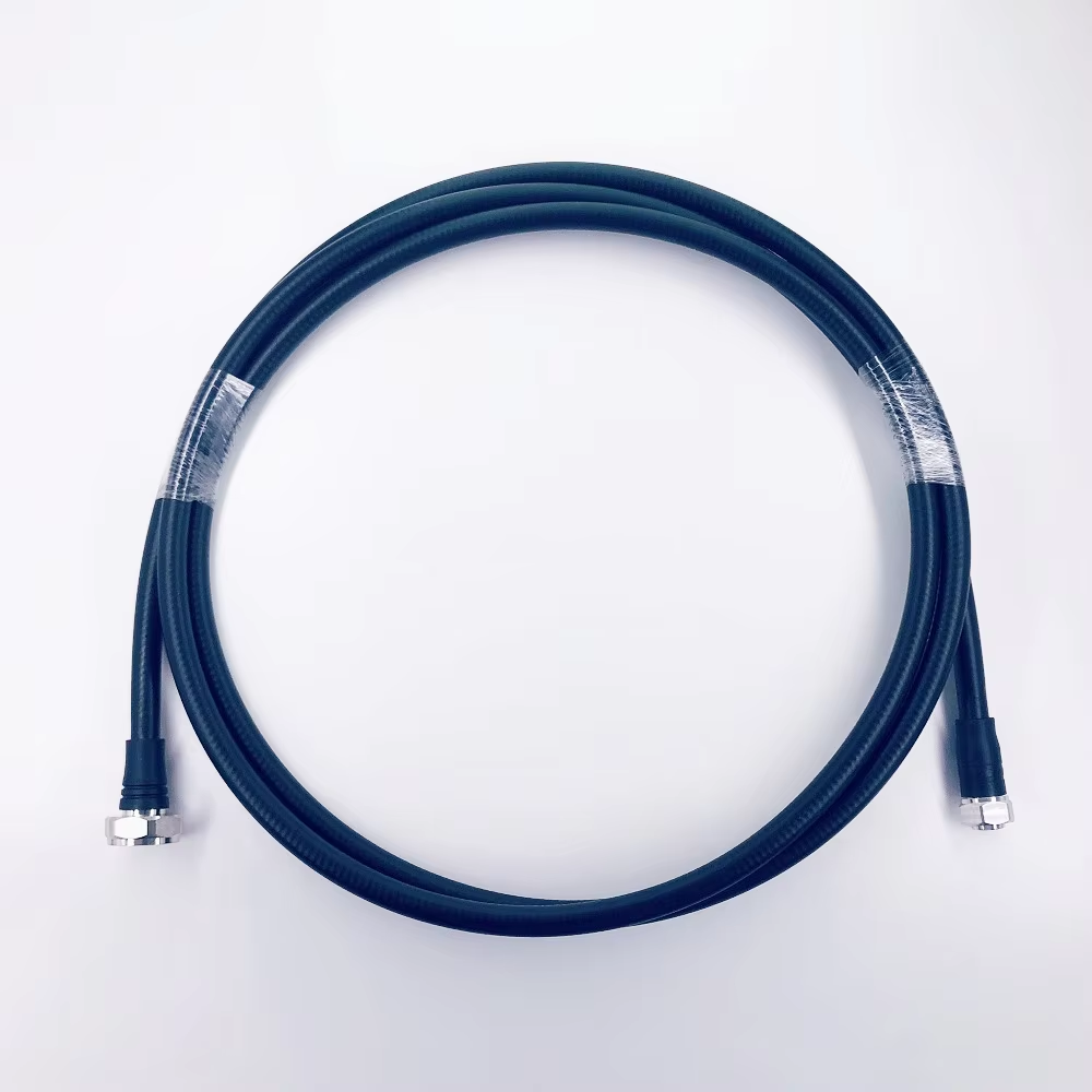
For an OEM program, custom coax cables are not simply a line item between two RF interfaces. They are a controlled signal path whose electrical behavior, mechanical fit, production repeatability, and inspection evidence all need to survive design release and volume supply. A cable that looks correct in a prototype can still create loss variation, connector damage, routing problems, or receiving-inspection disputes later in the program.
The most reliable way to assess custom coax cables is to translate the application into a written requirement, then test the supplier’s ability to manufacture and verify that requirement consistently. The checklist below is designed for procurement, RF engineering, quality, and manufacturing teams evaluating a custom RF cable assembly.
Start with the RF requirement, not the connector photo
A request such as “3.5 mm to 3.5 mm cable, two metres long” is not enough to qualify custom coax cables. Begin with the system limits: frequency range, nominal impedance, insertion-loss budget, return-loss or VSWR target, shielding need, power level, phase stability need, and the environment in which the assembly will operate. These inputs determine whether the selected cable construction and connector family are suitable.
Ask the supplier to state which electrical characteristics are controlled for the finished assembly and at which frequencies. Coaxial communications-cable standards in the IEC 61196 family address cable construction and attenuation-related testing, but the relevant part and acceptance limits must be agreed for the specific design. A generic reference to a standard is less useful than a drawing that defines the applicable frequencies, test setup, limits, and sampling plan.
- Frequency and impedance: Confirm the full operating band and the nominal impedance expected by the equipment.
- Loss and reflection limits: Define maximum insertion loss and minimum return loss, or an equivalent VSWR limit, at stated frequency points.
- Shielding and interference: Specify the required shielding effectiveness or transfer-impedance objective when the installation is sensitive to EMI.
- Phase and delay: For arrays, test systems, or matched channels, define phase matching, delay tolerance, and how flexing or temperature will be considered.
Do not accept a catalogue attenuation figure as the assembly result. Connector transitions, actual length, bend condition, and termination workmanship can all affect the finished measurement.
Evaluate the mechanical design for the real installation
OEM failures often originate in the mechanical envelope rather than the RF drawing. Map the routing path, available bend space, mating-access clearance, connector torque access, panel or chassis interface, and strain-relief direction. Specify the finished length with a clear reference: connector end face, cable end, or another defined datum. This avoids a common source of receiving discrepancies when different teams measure the same assembly differently.
For custom coax cables, the cable type should match the bend radius, movement profile, and installation environment. A low-loss cable may be appropriate electrically but impractical where repeated flexing, tight routing, or field handling are expected. Review jacket material, temperature exposure, abrasion, moisture, flame requirements, and any need for labeling or protective overmolding. If a harness has branches, specify breakout locations and tolerance zones rather than relying on a marked-up photograph.
Check design-for-manufacturability before approving samples
A first sample proves that one assembly can be built; it does not automatically prove that the design is scalable. Ask how the supplier controls cable cutting, strip dimensions, connector attachment, torque, soldering or crimping, cleaning, inspection, and packaging. The goal is to identify process steps that could create unit-to-unit variation.
Request a drawing revision with a bill of materials, approved cable and connector part numbers, assembly notes, critical dimensions, and test requirements. The supplier should identify alternatives only through a documented change process. This matters when a connector or cable raw material is unavailable: an unreviewed substitute can alter RF behavior or mechanical fit.
IPC/WHMA-A-620 provides an industry-consensus framework for cable and wire-harness workmanship and acceptance when it is included in the program requirement. For an RF assembly, it should complement—not replace—electrical performance criteria and connector-specific instructions.
Qualify the supplier’s verification plan
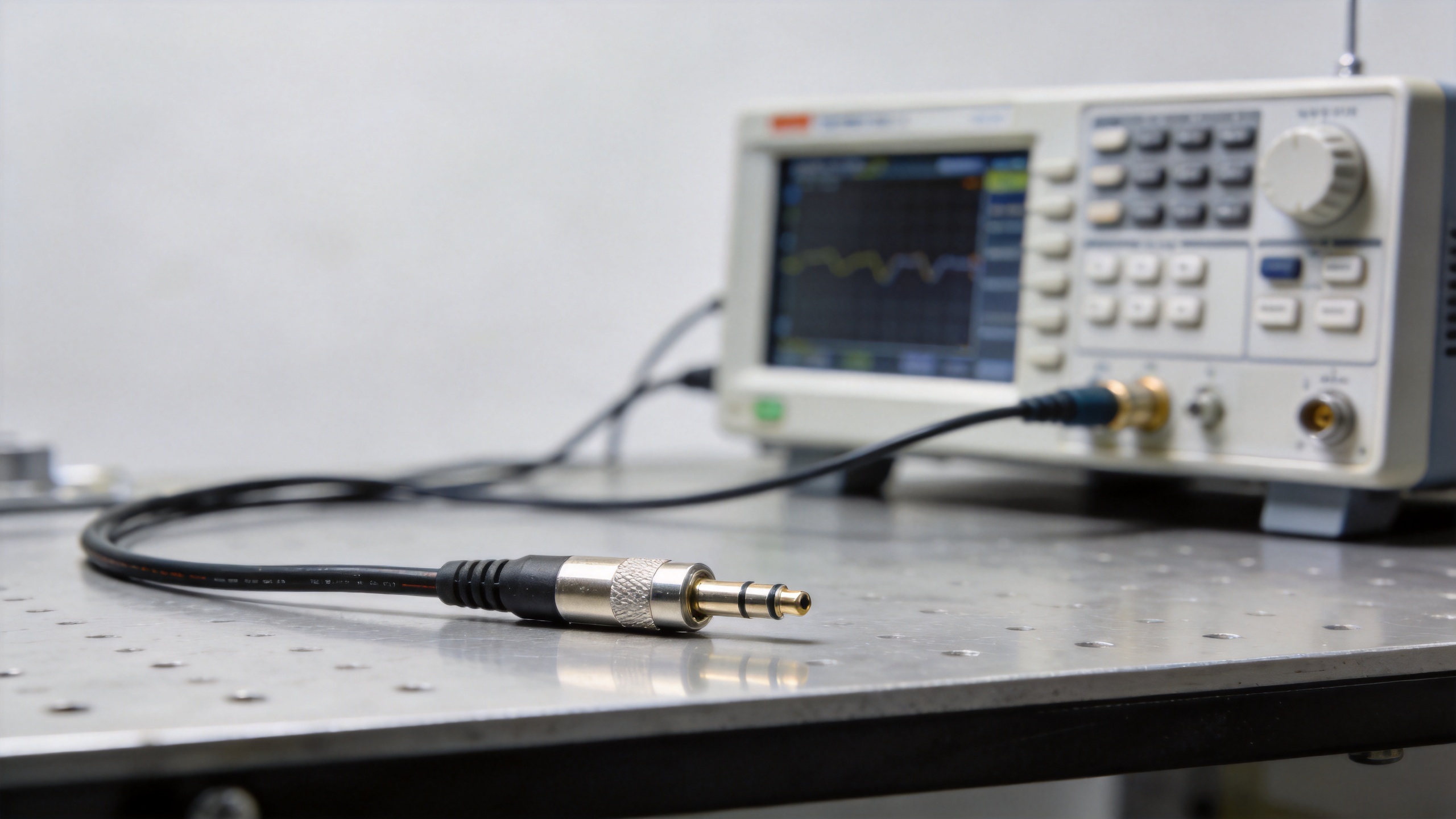
A useful qualification plan separates design verification from routine production testing. During first article evaluation, request dimensional records, visual workmanship evidence, continuity checks, and RF measurements appropriate to the design. Depending on the application, the plan may also include insertion loss, return loss or VSWR, insulation resistance, withstand-voltage testing, pull or retention checks, and environmental evaluation.
For production, define whether every unit, a statistically selected sample, or only a lot sample receives each test. The answer should follow the consequence of failure and the stability of the process. Also clarify the instrument type, calibration status, fixture configuration, frequency sweep, pass/fail limits, and format of the test record. A data sheet without a link to the delivered serial number or lot provides limited traceability.
Use a supplier scorecard instead of a price-only comparison
At the decision stage, compare custom coax cables with a weighted scorecard. Price is important, but it should sit alongside technical fit, evidence quality, supply continuity, response time, and change control. A practical scorecard can include the following categories:
| Category | What to verify |
|---|---|
| Electrical fit | Frequency coverage, impedance, loss, return loss/VSWR, shielding, phase needs |
| Mechanical fit | Length datum, bend radius, connector orientation, strain relief, installation access |
| Manufacturing control | Locked BOM, work instructions, critical-process controls, approved substitutions |
| Quality evidence | First article, test records, inspection plan, calibration, lot or serial traceability |
| Supply readiness | Prototype-to-production lead time, capacity communication, packaging, change notification |
For example, an OEM team comparing a 30GHz Low PIM 3506 Cable Assembly With 3.5M To 3.5M should use the product page as an identification point, then confirm the actual order drawing, configuration, and acceptance data rather than assuming a listed product defines every project requirement.
Release checklist for custom coax cables
Use this final gate before approving custom coax cables for a production release. It turns the engineering discussion into signable evidence and helps each function check custom coax cables against the same controlled record.
- Confirm that custom coax cables match the released frequency range and impedance requirement.
- Record the insertion-loss limit for custom coax cables at the defined frequency points.
- Record the return-loss or VSWR limit for custom coax cables and the measurement fixture.
- Verify the length datum and tolerance for custom coax cables.
- Verify the bend-radius and routing restrictions for custom coax cables.
- Verify connector gender, interface, orientation, and mating access for custom coax cables.
- Lock the approved cable, connector, and strain-relief BOM for custom coax cables.
- Document workmanship criteria and inspection checkpoints for custom coax cables.
- Review first-article dimensional and RF results for custom coax cables.
- Define production-test coverage and acceptance records for custom coax cables.
- Define lot or serial traceability for custom coax cables where the program requires it.
- Agree the packaging and handling method for custom coax cables.
- Require formal approval before any material or process change to custom coax cables.
When the record is complete, custom coax cables can move from prototype evaluation to controlled procurement with fewer assumptions. The OEM team can then compare custom coax cables by verified fit, evidence, and delivery control instead of by quotation alone.
Build approval around controlled evidence
Before releasing the purchase order, align engineering, quality, and sourcing on one controlled package: the drawing, BOM, revision level, approved sample or first-article record, test matrix, labeling and packaging requirements, and change-notification process. This package becomes the reference when production questions arise.
Well-qualified custom coax cables reduce late-stage troubleshooting because the team has already agreed what “good” means electrically, mechanically, and operationally. The supplier relationship is then evaluated on repeatable evidence—not on a promising prototype or a low initial quotation.