EN

How to Specify Low-Loss RF Feeder Cable for Telecom Projects
For a telecom project, rf cable loss is not a line-item detail—it is part of the link budget. A feeder that looks economical per metre can consume too much margin once frequency, route length, connectors, jumpers, and installation conditions are included. The practical goal is to turn an allowed rf cable loss figure into a clear, testable procurement specification.
This guide is written from a procurement-manager perspective for antenna feeds, radio links, distributed antenna systems, test installations, and other 50-ohm RF paths. It focuses on the questions that should be answered before requesting quotations, rather than assuming that one cable size fits every route.
Start With an RF Cable Loss Budget, Not a Cable Name
Begin with the radio system’s highest operating frequency, the available power margin, and the maximum permissible end-to-end insertion loss. In data sheets, attenuation is usually stated in dB per 100 m or per 100 ft at several frequencies. Because rf cable loss rises with frequency and cumulative length, use the value at or above your highest operating frequency—not a lower, more favorable table entry.
A useful working calculation is:
Total path loss = cable attenuation per unit length × installed length + connector loss + jumper loss + installation allowance.
The installed length should include vertical runs, horizontal routing, service loops, and reasonable routing contingency. Treat connectors and jumpers separately. They are not automatically included in a bulk-cable attenuation figure, and excluding them can make a nominal rf cable loss budget look safer than the completed assembly will be.
Ask the RF engineer to define both a normal target and a maximum acceptance threshold. The target protects operating margin; the threshold gives the site team an objective pass/fail value during commissioning.
Confirm the Electrical Interface Before Comparing Attenuation
Low attenuation is valuable only when the cable matches the system interface. For many telecom feeder applications, the required characteristic impedance is 50 ohms, but that must be confirmed against the equipment and antenna documentation. A mismatch can create reflected power and degrade return loss even if the cable’s published attenuation is low.
- Impedance: state the required nominal impedance and acceptable tolerance.
- Frequency range: specify the full operating band, including planned upgrades where practical.
- Attenuation: request a table at relevant frequencies and the maximum permitted value at the project frequency.
- Return loss or VSWR: define the measurement band and the minimum acceptable performance.
- Power handling: check continuous and peak conditions, including derating for ambient temperature and altitude if applicable.
These fields keep rf cable loss in context. A larger feeder may reduce attenuation, but it may also affect bend radius, connector selection, tower loading, and installation labor. Choose the cable that meets the complete electrical and mechanical requirement with realistic project margin.
Select Diameter and Construction for the Actual Route
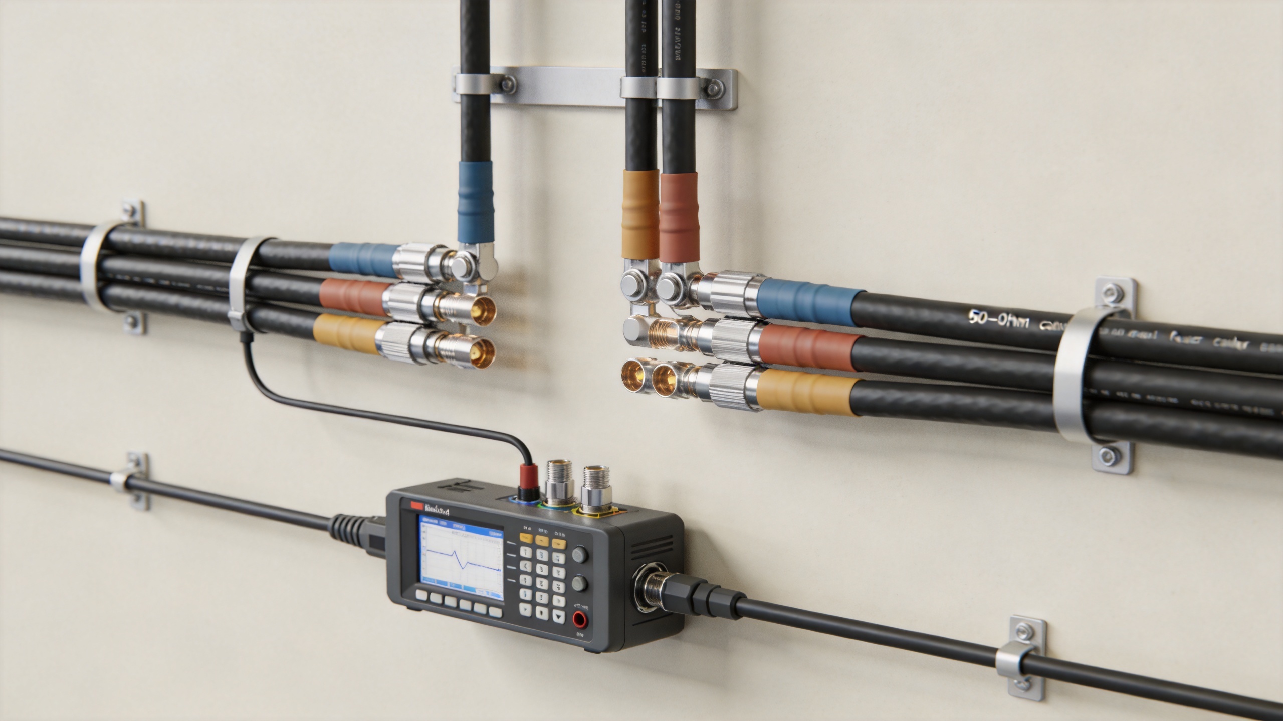
For a fixed construction family, a larger-diameter rf coaxial cable generally offers lower attenuation than a smaller one. That relationship often makes larger feeders attractive for long, high-frequency runs. Yet diameter is only one decision point. A rigid or semi-flexible cable can be efficient for long, stable outdoor routes, while a flexible section may be better near equipment, at transitions, or where repeated movement is expected.
Document the maximum route length, minimum bend radius, pulling method, support spacing, and available tray or conduit space. A cable that achieves low theoretical rf cable loss but cannot be installed within its bending limits may suffer deformation or connector stress. In practice, installation quality is part of the RF specification.
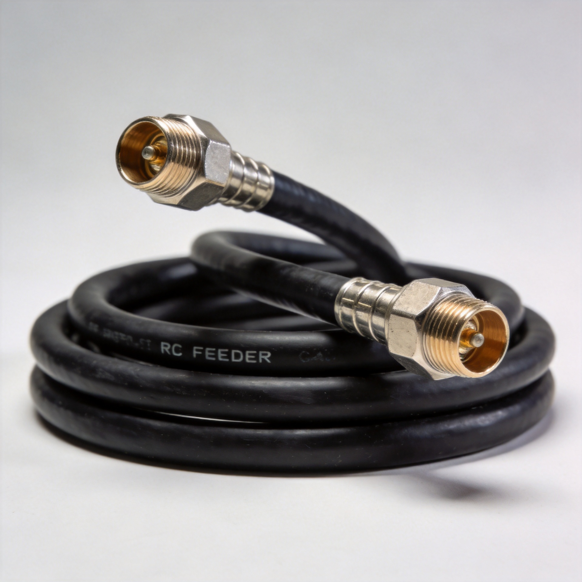
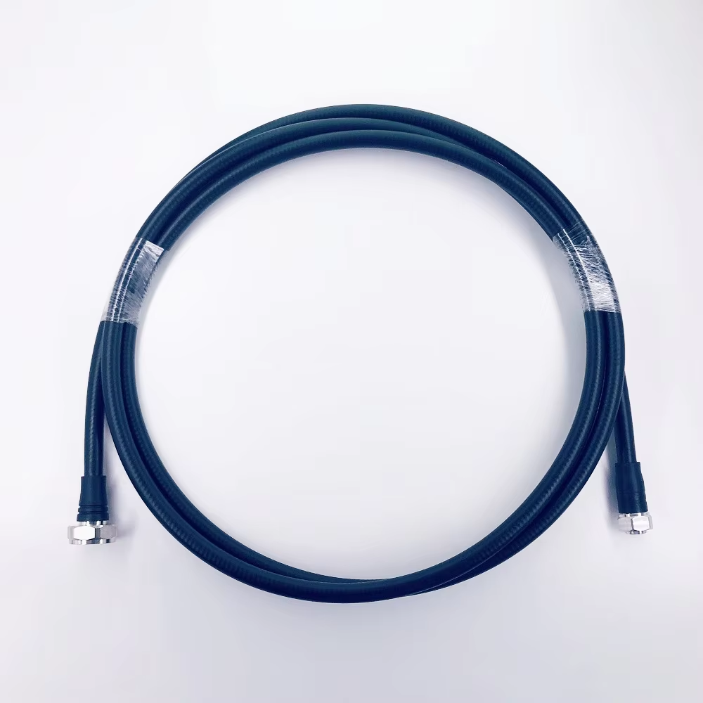
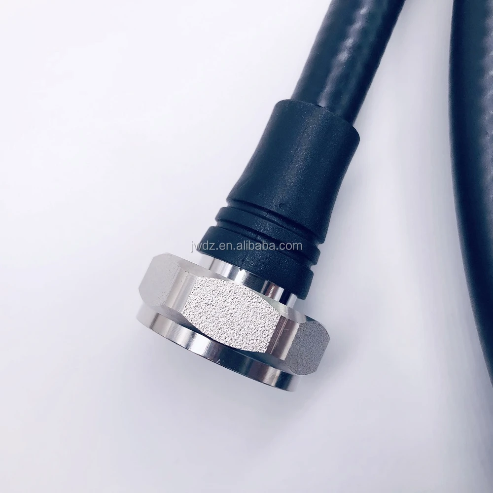
For an example of a project-relevant product category, buyers can review this 1/2-inch low-loss flexible feeder cable with a flame-retardant halogen-free jacket. Confirm the supplier’s current data sheet and compatible connector configuration before assigning it to a specific link.
Specify the Jacket, Environmental Rating, and Fire Requirements
Outdoor exposure, indoor risers, equipment rooms, tunnels, and coastal sites do not impose the same requirements. The cable specification should identify UV exposure, moisture sealing, temperature range, flame behavior, and any halogen-free or low-smoke requirement. These choices can affect construction, availability, price, and installation practice, so they belong in the request for quotation rather than in an afterthought.
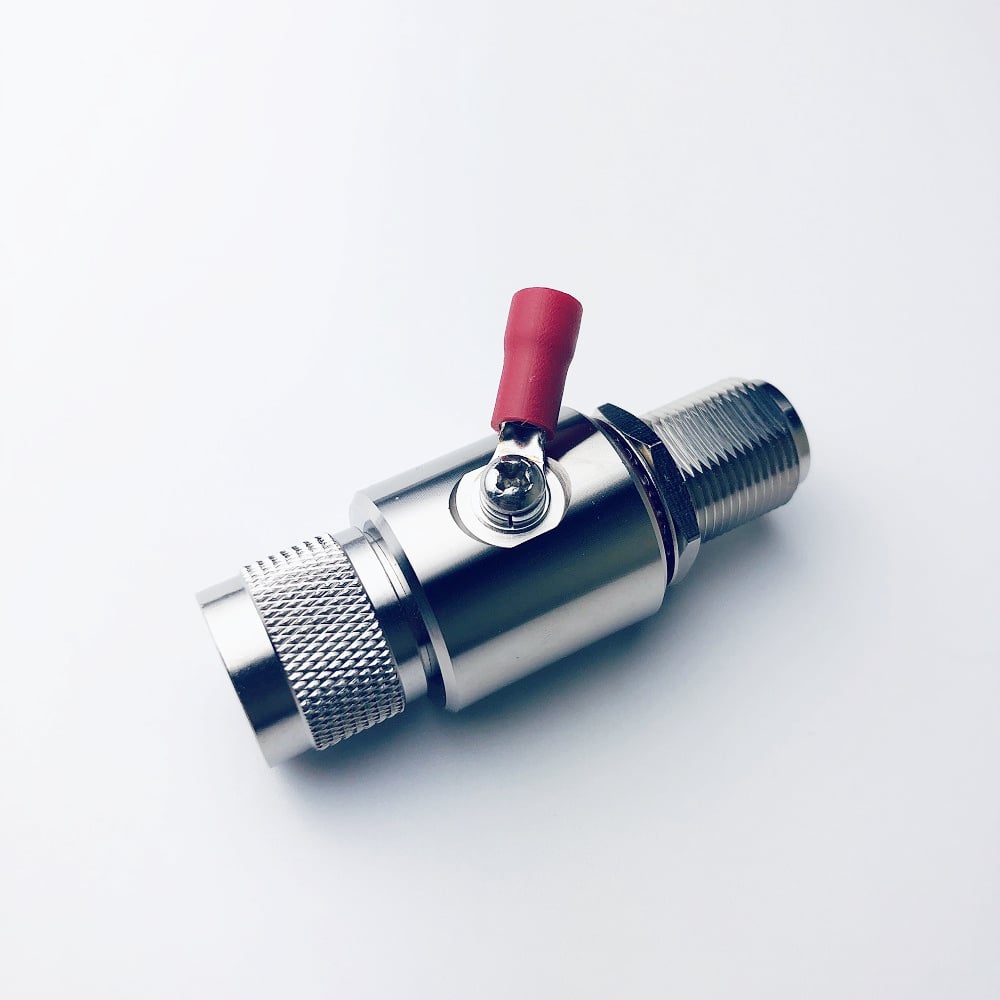
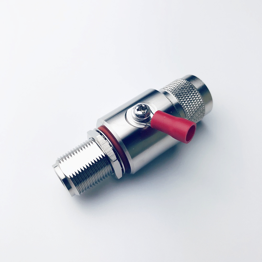
Also identify the grounding and lightning-protection approach for the whole feeder system. Grounding kits, weatherproofing, connector interfaces, and transition hardware should be compatible with the selected feeder diameter. A low published rf cable loss number does not remove the need to manage water ingress and connection reliability over the project lifecycle.
Make Connector and Assembly Details Part of the Purchase Specification
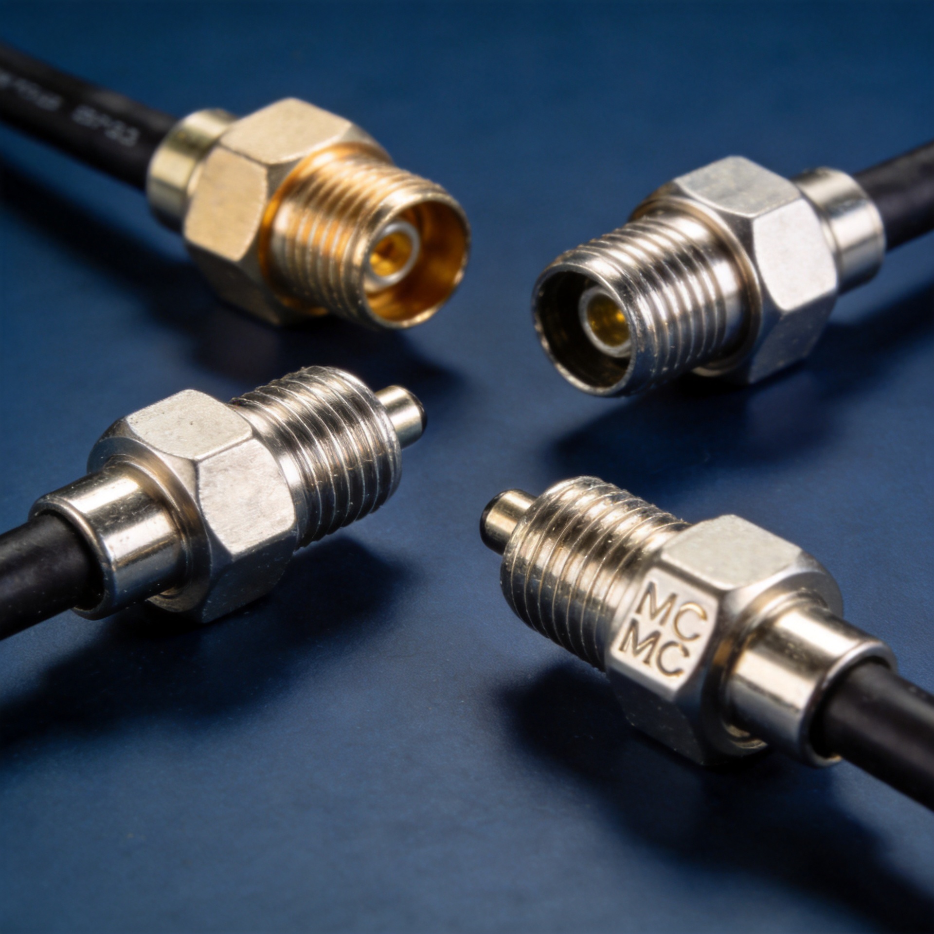
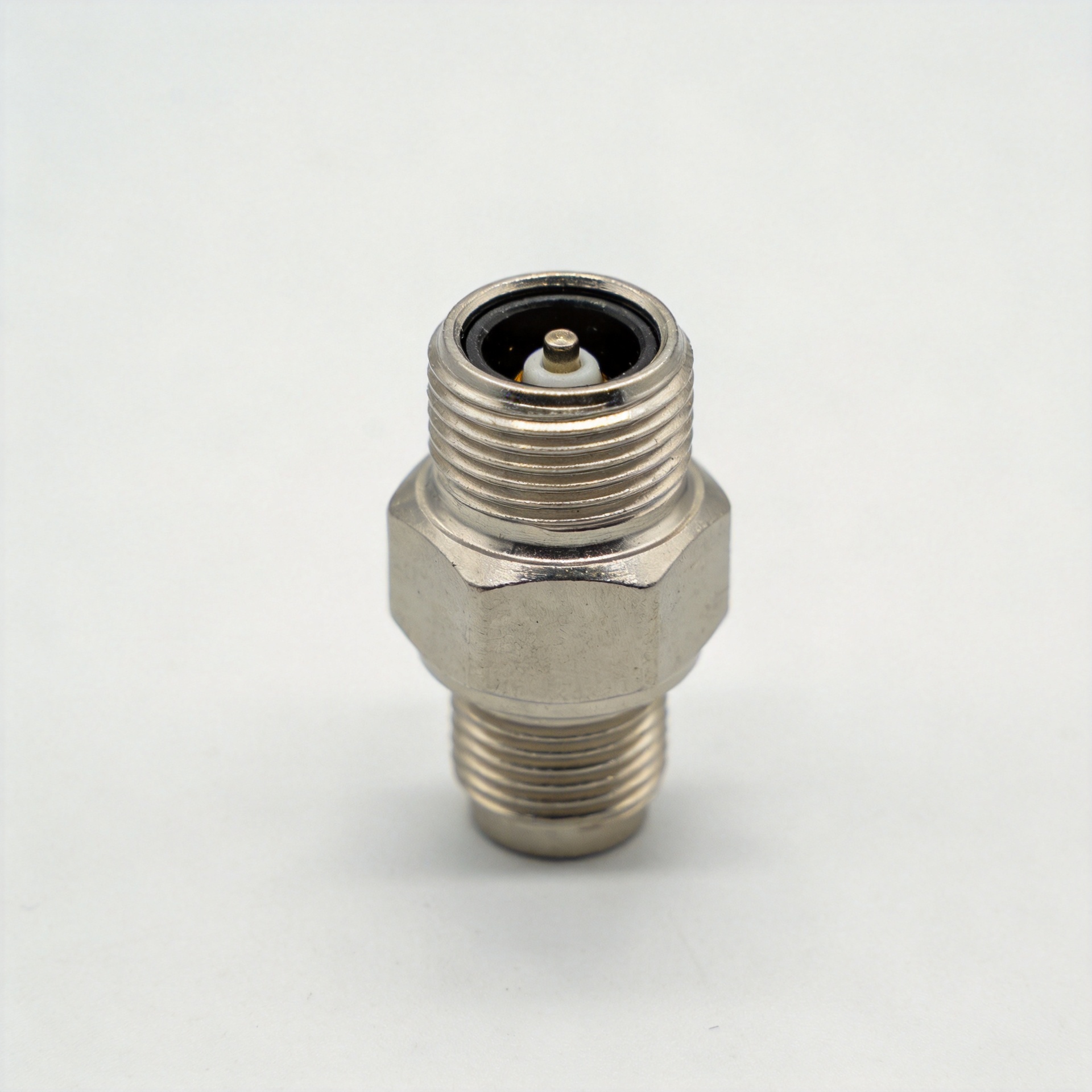
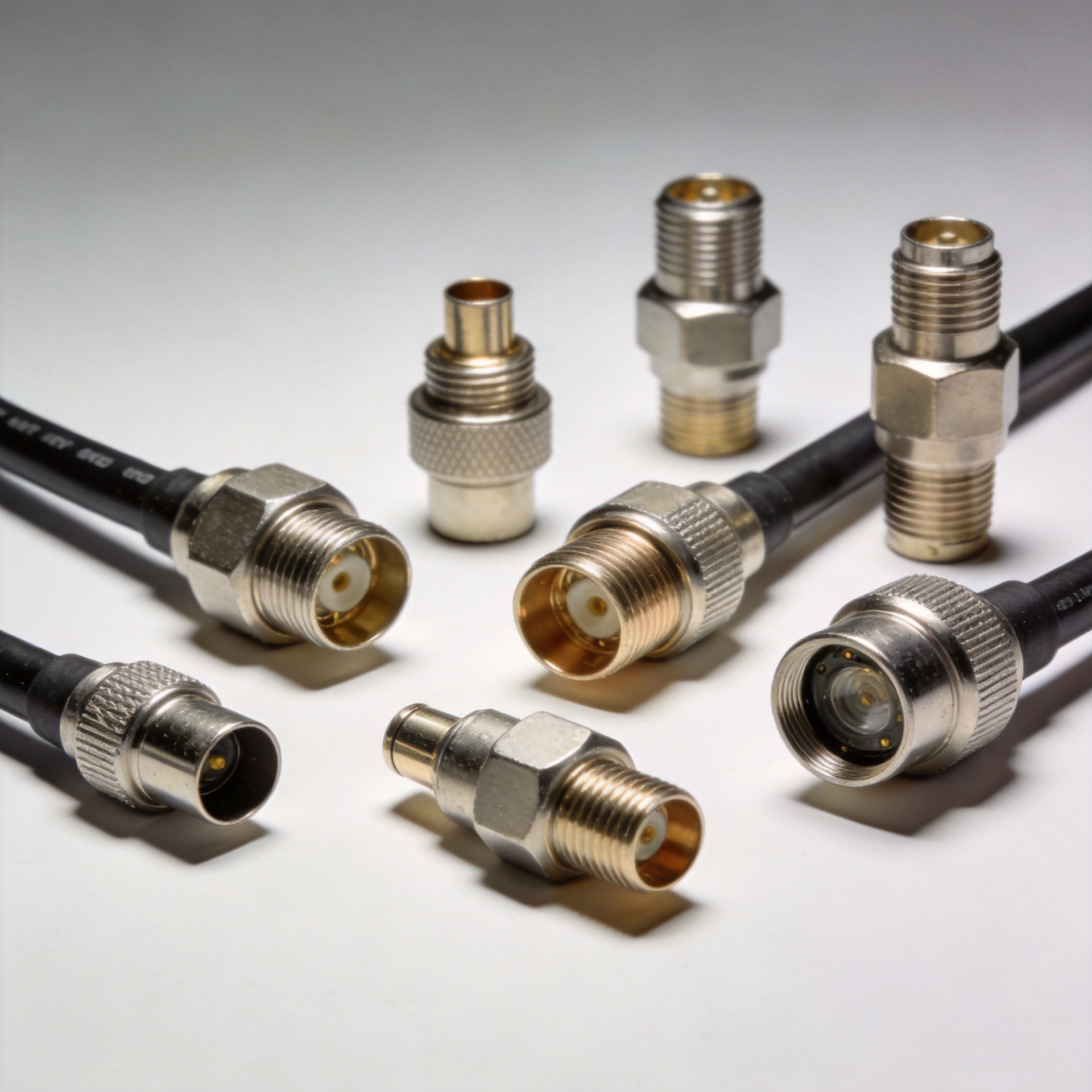
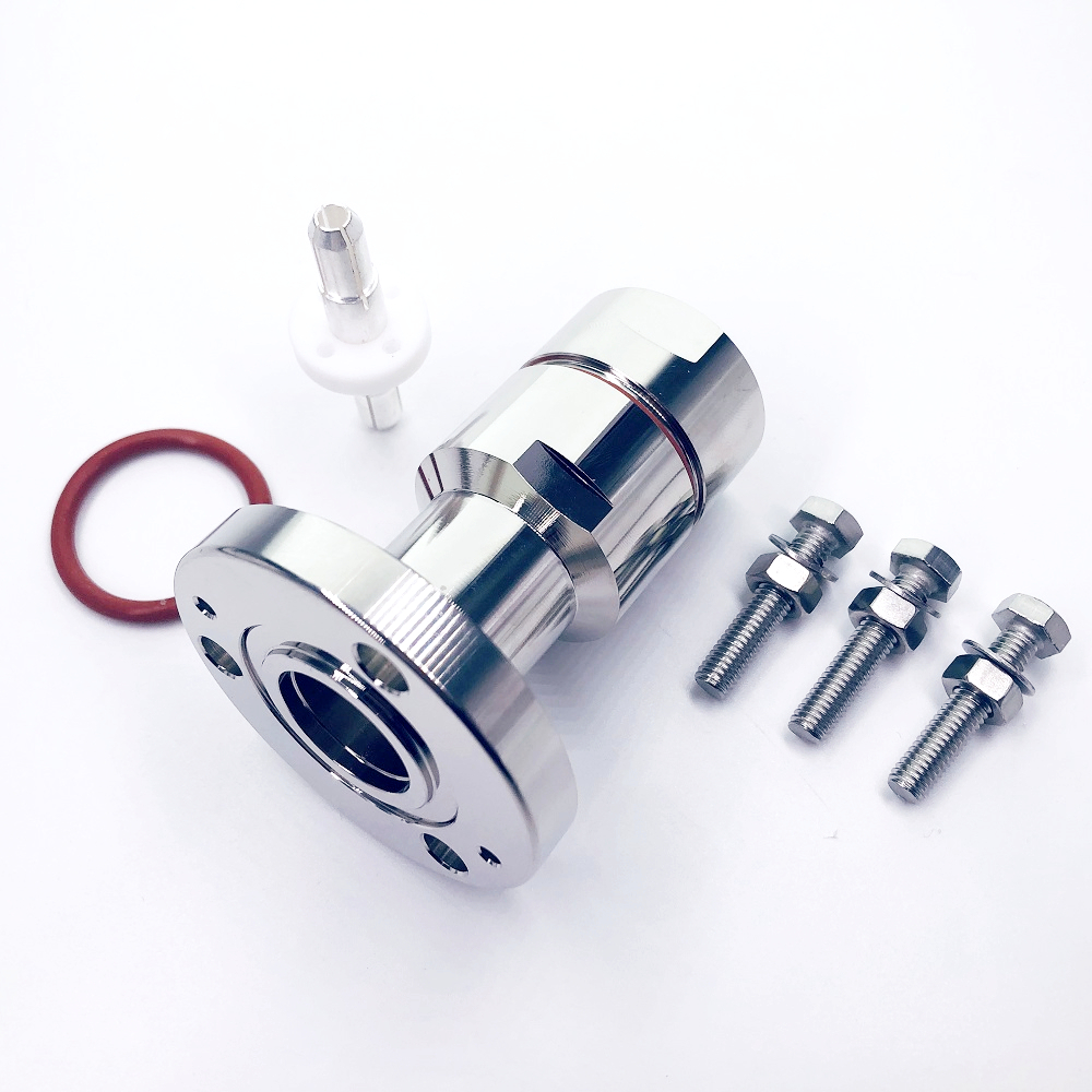
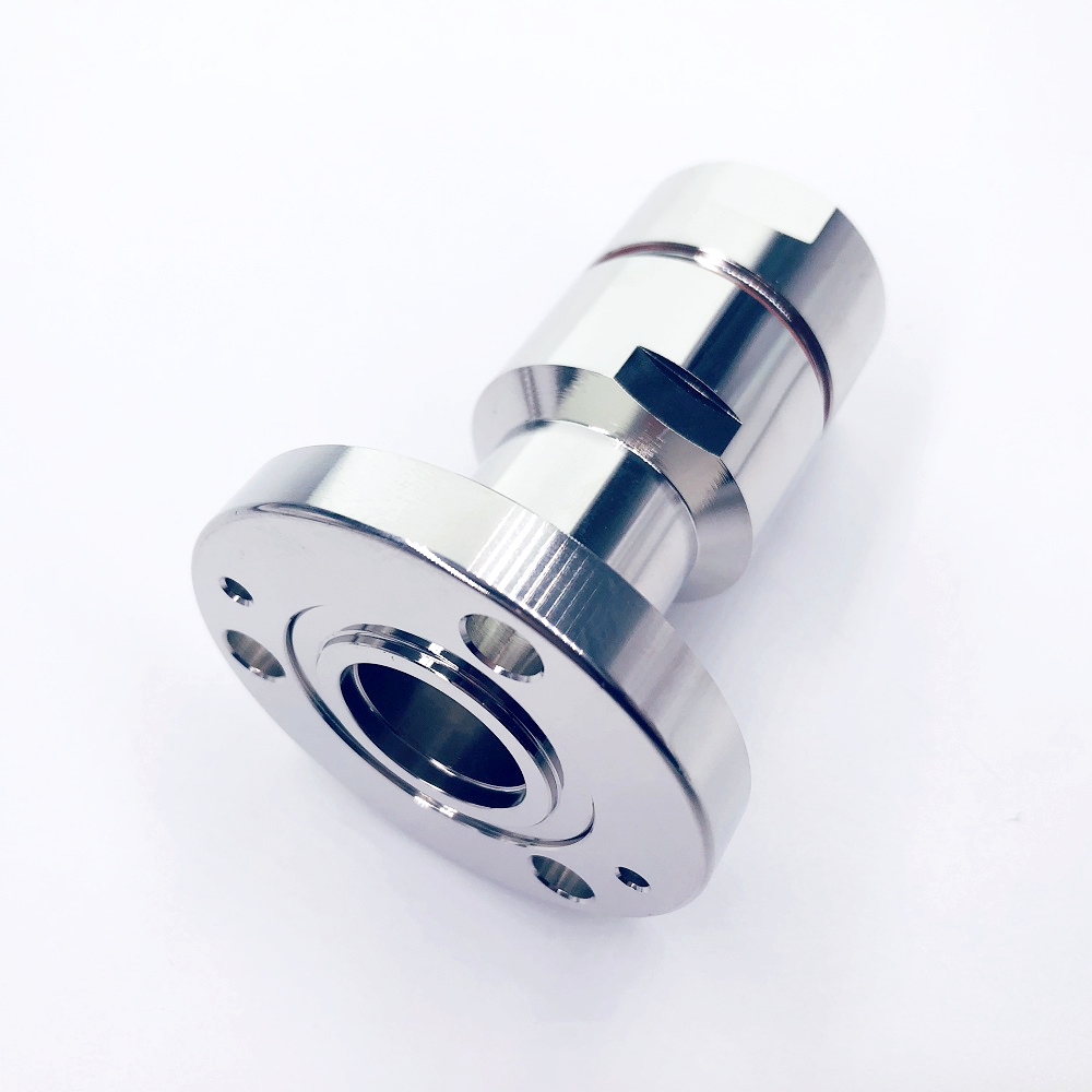
Procure a feeder assembly as a matched electrical path, not just cable plus miscellaneous connectors. State the connector interface at each end, gender, straight or right-angle form, mating torque requirements, weatherproofing needs, and whether factory termination is required. For remote or exposed connections, clarify the sealing method and inspection criteria.
Connector quality matters because poor preparation, incorrect torque, or incompatible parts can add loss and reflection. When evaluating rf cable loss, request the supplier’s assembly test scope: frequency band, insertion-loss method, return-loss or VSWR method, and identification traceability. A factory test record can simplify site acceptance, but it should not replace final installed-path testing.
Use a Decision Checklist Before Releasing the PO
| Specification item | What to confirm | Why it matters |
|---|---|---|
| System band | Lowest and highest operating frequencies | Sets the applicable attenuation and return-loss limits. |
| Loss budget | Target and maximum installed-path loss in dB | Converts rf cable loss into an acceptance criterion. |
| Route length | Installed length, service loops, and contingency | Prevents underestimating cumulative attenuation. |
| Impedance and connectors | Nominal impedance, interface, gender, and torque requirements | Controls mismatch and connection errors. |
| Environment | UV, moisture, temperature, fire, and jacket requirements | Protects long-term reliability. |
| Verification | Factory records and field insertion-loss/return-loss test plan | Confirms the completed link, not only the catalogue value. |
Plan Acceptance Testing Around the Installed Link
Acceptance should verify the route after cable pulling, terminations, grounding, and weatherproofing are complete. Compare measured insertion loss and return loss against the approved limit over the actual operating band. If a result is outside tolerance, isolate whether the issue comes from cable damage, excessive bend stress, a connector, water ingress, or an incorrect interface.
Keep the approved data sheet, cable drum or assembly identification, test results, and route records together. This documentation supports maintenance teams and makes later network expansion easier to evaluate. It also creates a defensible record of how the project controlled rf cable loss.
Conclusion: Write a Performance Requirement That Can Be Verified
The strongest feeder specification begins with system performance, then works outward to impedance, highest frequency, route length, allowable rf cable loss, power, construction, jacket, and connectors. Avoid selecting solely by cable diameter or an isolated attenuation number. Instead, require a complete data sheet, compatible assembly details, and an installed-path test plan.
For telecom buyers, this approach turns an rf coaxial cable purchase into a controlled RF decision: the selected feeder is sized for the actual route, protected for its environment, and verified against a loss budget that the project team can measure.