EN
EN

Flexible RF Cables: When to Choose Them for Telecom Routing
A telecom routing drawing can look far tidier than the installed path. A radio shelf, filter, test point, remote unit, or antenna interface may leave little room for a straight run. In those situations, flexible RF cables can make installation more practical without abandoning the electrical discipline that RF paths require. The right choice is not simply the softest cable available; it is the assembly that meets the system’s impedance, frequency, loss, power, connector, and service-access needs after it has been routed.
From an installation perspective, the cable choice affects how quickly a route can be completed and how often it must be revisited. Flexible RF cables are especially useful when the route changes direction, passes through crowded equipment, or needs a manageable service loop. They are not automatically the right answer for every long or high-power run, however.
What makes flexible RF cables useful in telecom equipment?
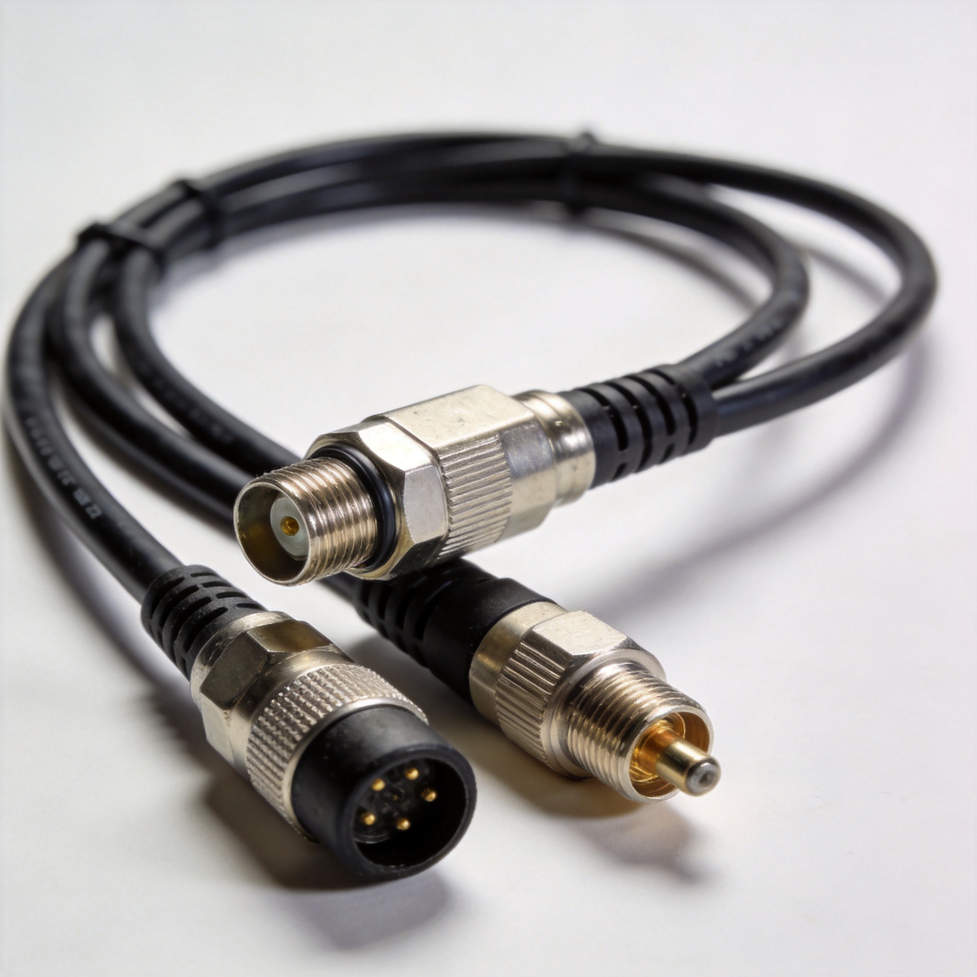
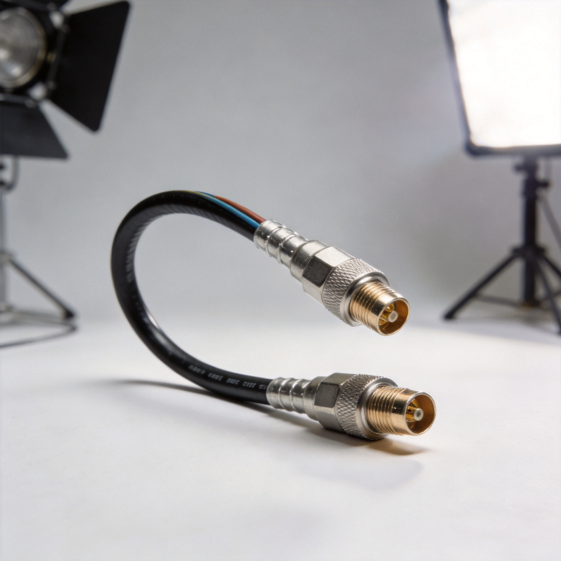
Flexible RF cables are coaxial assemblies designed to bend more easily than semi-rigid alternatives while preserving a controlled RF transmission path. Many telecom interconnects use a 50-ohm system, so the assembly must retain the intended impedance through the cable and connector interfaces. Flexibility helps installers route a cable around chassis hardware, avoid sharp hardware edges, and reach ports without placing a sustained side load on a connector.
That advantage matters in equipment interconnects, where the distance may be short but the path is complex. Think of a connection between an RF module and a panel-mounted interface, a rack-mounted radio and a filter, or a test instrument and a device under evaluation. Flexible RF cables can simplify those paths when a rigid route would demand awkward adapters or a semi-rigid shape that is difficult to modify during installation.
There is an important boundary: flexibility does not erase electrical trade-offs. A smaller or more pliable construction may have a different attenuation, power-handling, shielding, or bend-radius specification than a larger low-loss cable. Treat flexible RF cables as a routing tool within an engineered cable selection—not as a substitute for a loss budget.
Choose flexible RF cables when the routing path is changing or constrained
The clearest use case for flexible RF cables is a route with multiple direction changes. Equipment cabinets often contain power wiring, cooling hardware, control harnesses, and RF components competing for the same space. A flexible assembly can follow a planned path with fewer mechanical conflicts, provided each bend stays within the cable manufacturer’s minimum bend radius.
A common planning rule of thumb for flexible coax is a bend radius of roughly five to ten times the cable outside diameter, but the product datasheet is the controlling requirement. A cable that fits around a corner only because it is forced into a tighter bend may develop a kink, altered geometry, or connector stress. For flexible RF cables, a route should include gradual turns, suitable clamp locations, and a little slack for service—not a tight coil pushed behind a panel.
Use this option when technicians may need to remove or replace a module. A small, controlled service loop can make access easier, while a rigidly formed run may need to be rebuilt after every change. Here is the question worth asking before finalizing a routing drawing: can the connector be mated and unmated without twisting the cable body or pulling the assembly against its strain-relief area?
Use them for equipment interconnects, not by default for every feeder run
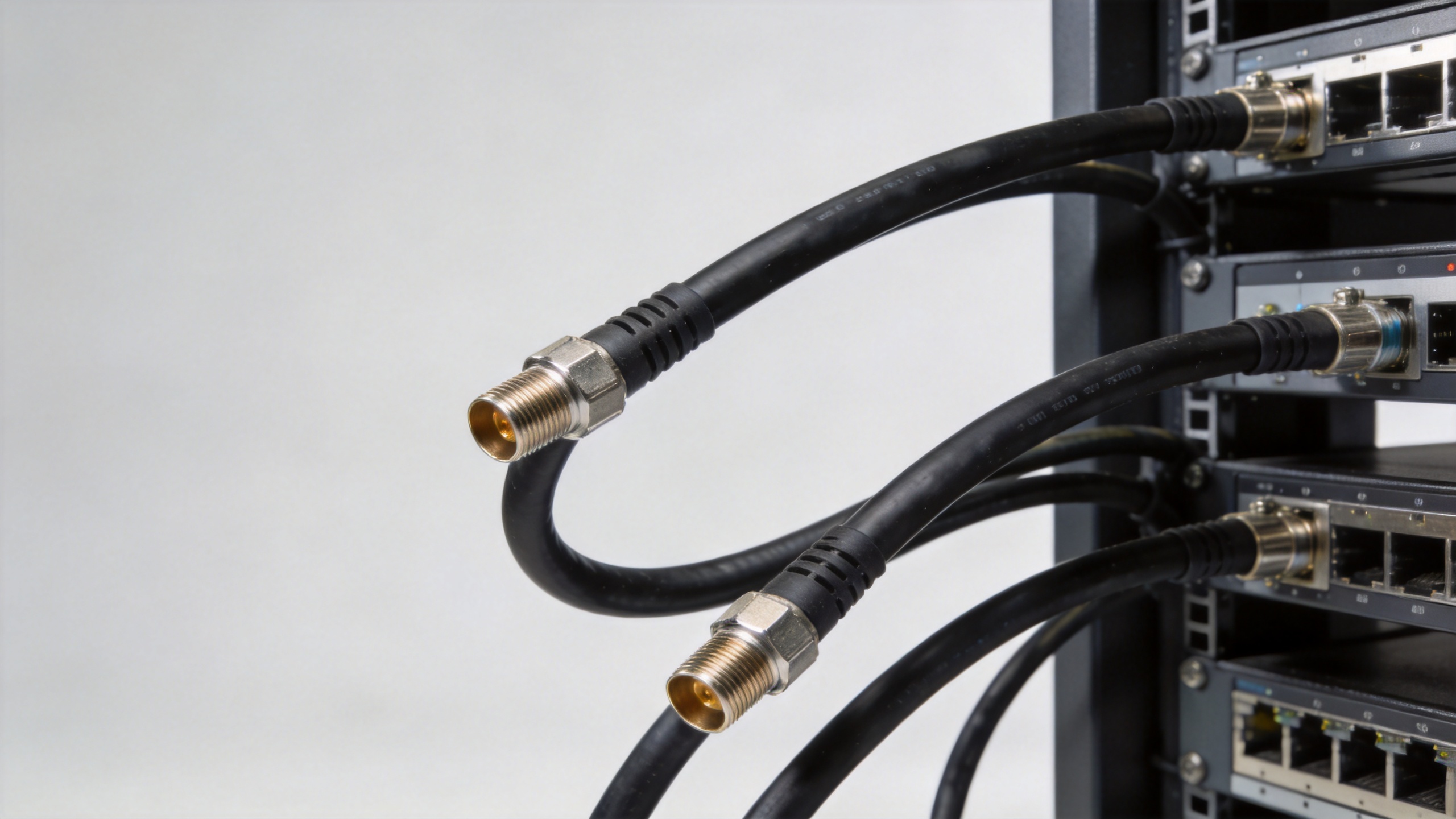
Flexible RF cables work well for short-to-medium equipment interconnects where installation access and route complexity are central concerns. They can also suit indoor jumpers, test setups, cabinet links, and protected connections that need periodic movement. In a controlled indoor environment, a standard flexible assembly may be an efficient choice. If the cable will see UV exposure, moisture, condensation, vibration, or repeated temperature cycling, begin with the environmental requirement rather than with flexibility or unit price.
For a long feeder run, a high-power route, or a path where attenuation margin is tight, compare the loss budget before deciding. A more rigid or larger low-loss cable may better support that run. The useful decision is often mixed: choose flexible RF cables near equipment interfaces where routing and maintenance matter, then use the cable type that most appropriately meets loss and environmental requirements for the longer path.
This is also why a cable assembly should be specified as a system. Frequency range, insertion loss, power, voltage, temperature range, shielding, connector series, and length all influence the outcome. The connector interface must match the equipment port and the planned mating cycle. A route that protects the cable but leaves no room to operate a coupling nut is not a serviceable route.
Protect connector terminations and manage strain relief
Most routing failures do not begin in the middle of a straight cable run. They begin at a tight bend beside a connector, an unsupported hanging section, or a cable tie tightened too aggressively. Flexible RF cables should be supported so their weight and movement are not transferred directly to the connector termination. Keep the first bend away from the connector according to the assembly guidance, use appropriately spaced clamps, and avoid sharp tie-wrap pressure that can deform the jacket.
My default used to be selecting the lowest-priced assembly that appeared to meet a minimum specification. One corrosion or rework event quickly changes the calculation: the delivered cost includes access time, retesting, downtime exposure, and replacement labor. Passing a qualification test is the entry condition, not the destination. For an outdoor or vibration-prone path, the better question is what the assembly will look like after years of environmental stress.
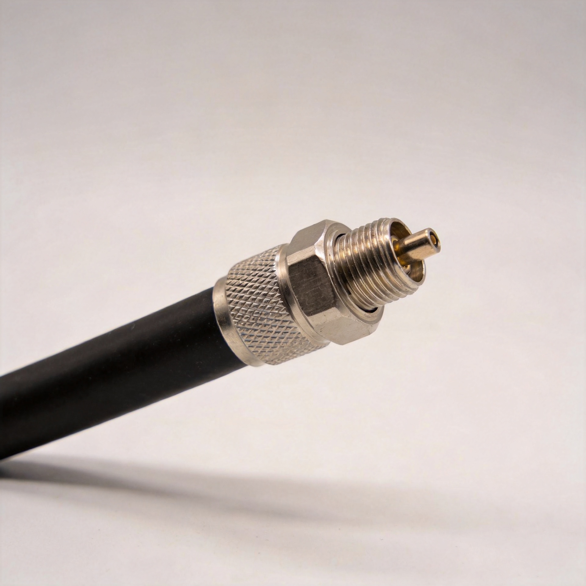
Where a custom assembly is needed, confirm the cable type, finished length, connector orientation, and strain-relief requirement before release. A 4.3-10 to N male RF coaxial jumper cable assembly is one example of a defined interface pairing; it should be evaluated against the actual ports, cable family, and routing conditions rather than treated as a universal replacement.
A practical selection sequence
- Define the electrical path. Confirm operating frequency, nominal impedance, allowable insertion loss, and power requirement. Flexible RF cables must fit the RF budget before they are approved for mechanical convenience.
- Map the physical route. Note corners, clearances, hot surfaces, moving hardware, and access points. Mark the supplier-specified bend-radius zones.
- Select cable construction. Compare flexible, conformable, and more rigid options for the needed movement, shielding, attenuation, and environmental exposure.
- Specify the terminations. Check connector series, gender, mounting interface, orientation, torque and mating access. Specify strain relief when the route puts load near the connector.
- Plan verification. Inspect the installed route for kinks, crushed sections, unsupported weight, and excessive side load; then perform the appropriate RF verification for the application.
When not to choose flexible RF cables
Do not choose flexible RF cables solely because the cable must make a tight turn. If the required turn is tighter than the stated bend radius, redesign the route, change the cable size or construction, or add space. Likewise, do not assume flexible RF cables are the preferred choice when a long run needs the lowest practical attenuation, when the route is permanently fixed and well supported, or when environmental exposure demands a different cable construction.
The same principle applies to repeated flexing. Some flexible assemblies are made for installation routing, not continuous motion. If a cable will move repeatedly, define the movement profile and confirm that the selected construction is suitable. This is a case where the specification that matters most is not the word “flexible,” but the documented mechanical and electrical limits for the exact assembly.
Final routing checklist
- Choose flexible RF cables when installation geometry, service access, and controlled routing benefit from bendability.
- Verify 50-ohm compatibility and calculate loss, power, and frequency requirements for the complete path.
- Use the published bend radius; do not force a cable into a smaller turn.
- Keep stress away from connector terminations and provide appropriate support.
- For outdoor, high-power, long-distance, or moving applications, evaluate the environmental and electrical requirements before prioritizing flexibility.
The practical takeaway is that flexible RF cables are most valuable when they make a telecom route easier to install, inspect, and maintain while the selected assembly still meets the system’s measured performance requirements. A route planned around both mechanical reality and RF limits is more likely to remain reliable after installation.