EN
EN

LMR-400 Coaxial Cable: Complete Technical Specifications, Signal Loss Chart and Application Guide
Sizing a feeder cable for a long outdoor run looks straightforward until the system goes live. I've seen RF engineers choose cable based on impedance alone, only to find that LMR 400 cable loss at their actual operating frequency was consuming more link budget than modeled. The lmr400 cable loss figure that matters is the dB per 100 feet at your specific deployment frequency—not just the headline impedance number.
This guide covers the complete LMR 400 technical specifications, a verified cable loss reference table by frequency, and application guidance for WiFi, broadcast, and mobile communications—with comparisons against RG-8/U and LMR-600.
LMR 400 Technical Specifications
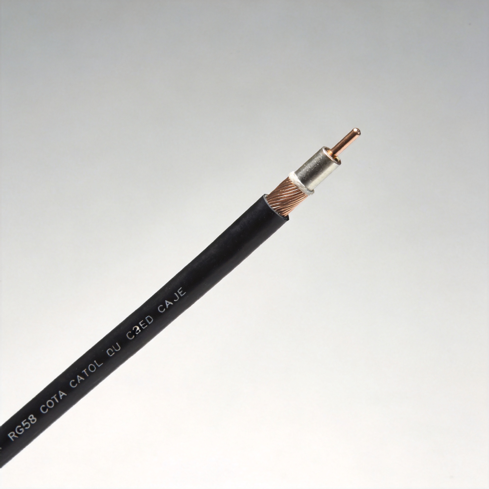
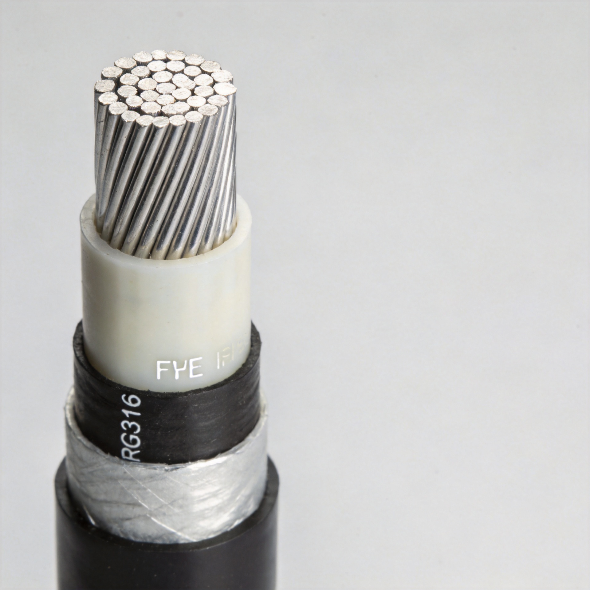
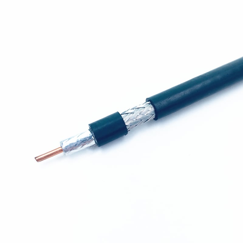
LMR 400 is a 50-ohm, double-shielded coaxial cable with low cable loss across a frequency range extending to 8 GHz. The design trades off cable diameter and flexibility to keep cable loss low across outdoor-rated temperature and UV conditions—a combination that covers a wide range of professional RF infrastructure requirements.
| Parameter | Value |
|---|---|
| Impedance | 50 ohms |
| Maximum Frequency | 8 GHz |
| Velocity Factor | 85% |
| DC Resistance (center / shield) | 1.39 / 1.65 Ω per 1,000 ft |
| Minimum Bend Radius | 4 inches (102 mm) |
| Operating Temperature Range | −40°C to +85°C |
| Jacket Material | UV-resistant black polyethylene (PE) |
| Shielding Type | Double shield |
| Dielectric | Foam polyethylene |
Signals travel through LMR 400 at 85% of the speed of light in free space—a correction factor to apply when cutting assemblies to specific electrical lengths. The UV-resistant PE jacket extends service life in outdoor installations, limiting the cable loss degradation that accumulates over multi-year deployments on exposed runs.
LMR 400 Cable Loss by Frequency
Cable loss scales with frequency—the higher the frequency, the higher the lmr400 cable loss per unit length. At 900 MHz, a 1 dB per 100 feet difference in cable loss between two cable types translates directly into a measurable drop in delivered power. That attenuation figure at your operating frequency generally deserves more weight in your evaluation than the impedance spec.
| Frequency | LMR 400 Cable Loss (dB / 100 ft) | Approx. Power Retained |
|---|---|---|
| 900 MHz | 3.9 dB | ~41% |
| 1 GHz | 4.25 dB | ~38% |
| 5.8 GHz | 10.8 dB | ~8% |
At 2.4 GHz over a 100-foot run, LMR 400 keeps cable loss under 30%—a significant difference from RG-58, which loses over 70% of input power at the same frequency and length. For a 5 W transmitter on a 100-foot outdoor run to a 2.4 GHz antenna, that's roughly 3.5 W reaching the antenna with LMR 400 versus less than 1.5 W with RG-58.
At 5.8 GHz the numbers shift: at 10.8 dB per 100 feet, even a 50-foot run removes about 7.7 dB—cutting power to roughly 17% of input. For applications consistently above 3 GHz with runs exceeding 30 feet, evaluate whether LMR-600 offers a better cable loss budget before specifying LMR 400.
LMR 400 vs RG-8/U vs LMR-600
Selecting a coaxial cable comes down to which option meets the cable loss budget for your frequency, run length, and total cost of ownership. RG-8/U may look attractive per foot; factor in cable loss at your operating frequency and jacket degradation in outdoor conditions, and the economics often shift toward LMR 400 over the full deployment cycle.
| Cable | Cable Loss (dB / 100 ft) | Power Delivered (100 W in) | Relative Cost |
|---|---|---|---|
| RG-8/U | 2.39 dB | ~58 W | $ |
| LMR 400 | 1.63 dB | ~69 W | $$ |
| LMR-600 | 0.97 dB | ~80 W | $$$ |
LMR 400 delivers about 11 percentage points more power than RG-8/U at comparable run lengths, while remaining more flexible and cost-effective than LMR-600. For most runs up to 100 feet at frequencies between 400 MHz and 3 GHz, it hits the cable loss target without the stiffness and cost premium of the larger cable.
LMR-600 is worth considering when run lengths exceed 100 feet or operating frequencies are consistently above 2.4 GHz and cable loss margins are tight. Outdoors, the LMR 400 PE jacket and double-shield construction provide cable loss protection over time that lower-grade alternatives don't sustain.
Application Guide
WiFi and WLAN Feeders (2.4 GHz / 5.8 GHz)
At 2.4 GHz, LMR 400 is widely used for outdoor access point feeders and DAS trunk cables where run lengths exceed 20 feet. Cable loss at 2.4 GHz stays within bounds for enterprise WiFi deployments, and the UV-resistant jacket handles rooftop installations without the jacket degradation that drives up cable loss over multi-year cycles.
Broadcast and Cellular Tower Feeders (700 MHz – 2.1 GHz)
LMR 400 replaces legacy RG-8 and 9913 cables on VHF/UHF broadcast feeders. The double shield provides isolation in dense RF environments, and cable loss at 700–2100 MHz fits most tower feeder link budgets without requiring the larger LMR-600 diameter and associated hardware.
Mobile Communications and In-Building DAS
For mobile base station equipment rooms and in-building DAS, LMR 400 is a common specification at 900 MHz where a 50-foot run contributes under 2 dB of cable loss. At 2.1 GHz, model the run length against the LMR 400 attenuation figures to confirm the cable loss budget holds.
Connector Compatibility and Sourcing
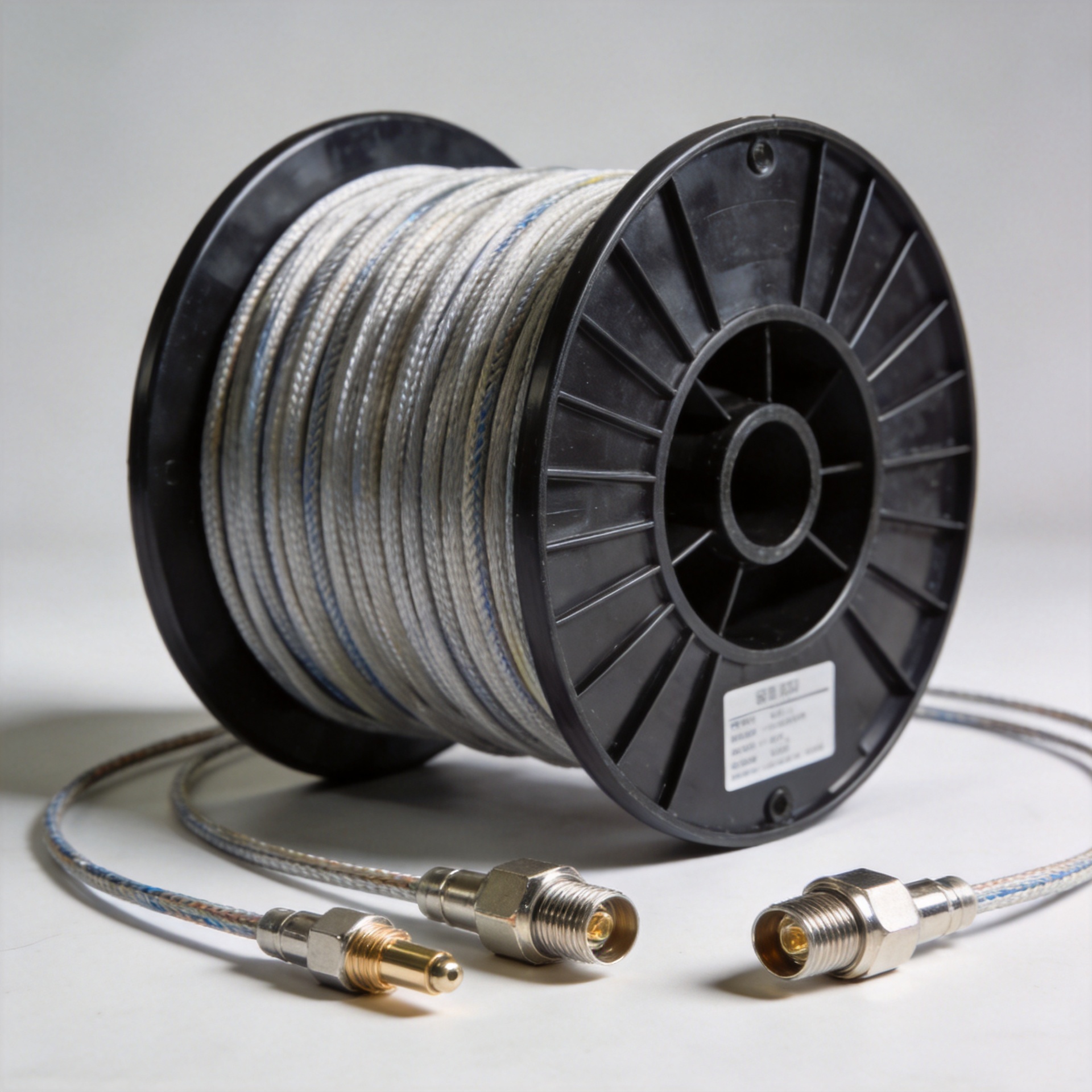
LMR 400 is compatible with N-type, 7/16 DIN, and 4.3-10 connector series. N-type connectors handle most field terminations; 4.3-10 assemblies suit equipment room patch positions. Sourcing pre-terminated LMR 400 assemblies from a manufacturer that controls both cable and connector production reduces batch-to-batch variation—a source of unexpected cable loss that doesn't surface in standard incoming inspection.
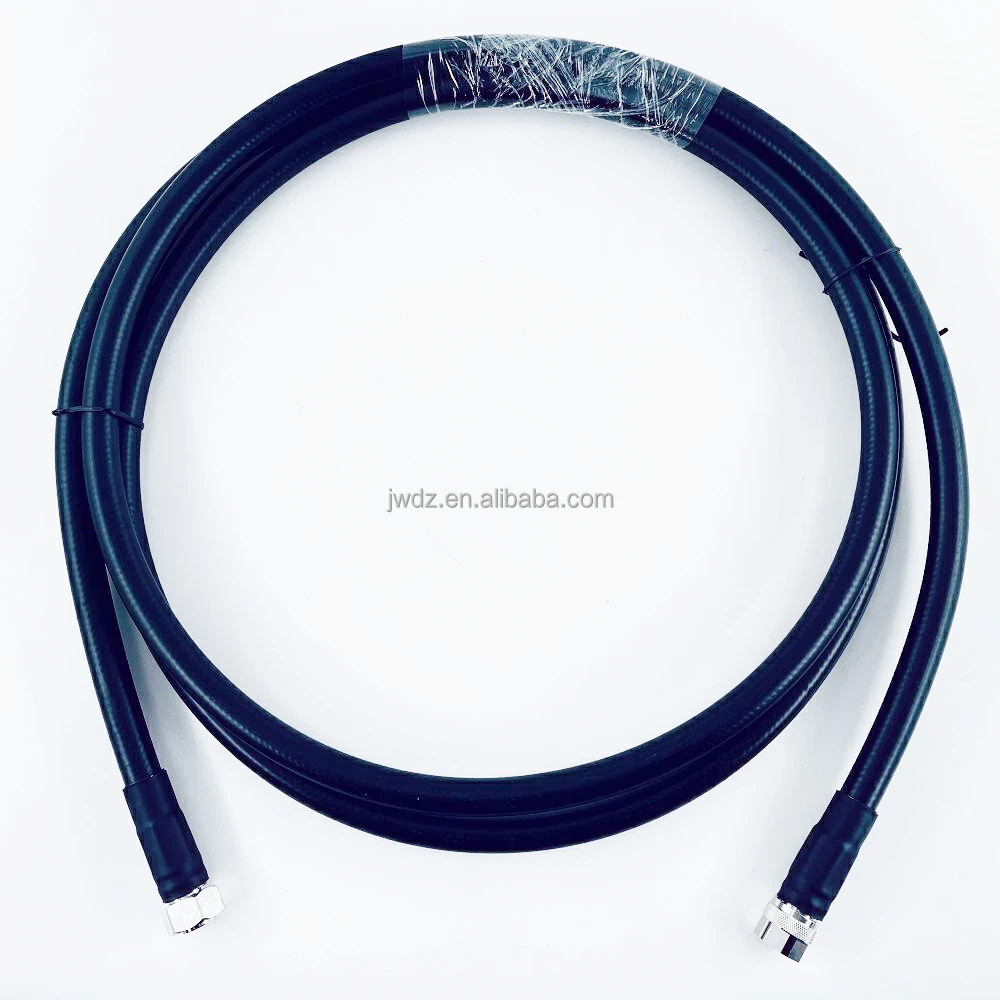
Zhenjiang Jiewei Electronic Technology has manufactured RF connectors, feeder cables, and cable assemblies for 25 years, supplying telecom, broadcast, and DAS customers globally. Their LMR 400 flexible low-loss coaxial cable is available in custom lengths for infrastructure projects, and their 4.3-10 to N Male LMR 400 cable assemblies are available for base station and tower feeder applications.
Summary
LMR 400 is a 50-ohm, double-shielded coaxial cable rated to 8 GHz. Verified cable loss values: 3.9 dB/100ft at 900 MHz and 10.8 dB/100ft at 5.8 GHz. The 85% velocity factor, 4-inch minimum bend radius, and UV-resistant PE jacket suit outdoor RF feeders operating between 400 MHz and 3 GHz.
For runs under 100 feet below 2.4 GHz, LMR 400 covers most link budgets with practical flexibility and cost. For longer runs or higher frequencies, compare cable loss against LMR-600 before specifying. Where outdoor longevity matters, the double shielding and UV jacket provide cable loss stability over time that simpler RG-8/U alternatives don't sustain across extended deployment cycles.